Replacement Parts And
Accessories
WARNING: Use only replacement parts and accessories described in this manual. Use of other parts or accessories could damage saw or injure operator.
For original replacement parts and accessories, contact your nearest Authorized Dealer or Authorized Service Center for this product. If they can not supply the part or accessory, contact your nearest Parts Central listed on page 28. Each Authorized Dealer,
Authorized Service Center, and Parts Central is independently owned and operated. See pages 16 and 17 for an Illustrated Parts List.
If you need additional referral information, contact our Technical Service Department
(see Technical Service).
In Canada call 1-800-561-3372 for parts information.
Technical Service
You may have further questions about assembling, operating, or maintaining this product. If so, you can visit our Technical Service web site at www.desatech.com or contact our Technical Service Department at 1-800-858-8501 (English Only). You may also write to:
DESA Specialty Products???
P.O. Box 90004
Bowling Green, KY 42102-9004
ATTN: Technical Service Specialty Products
When contacting DESA Specialty Products???, have ready
???Your Name
???Your Address
???Your Phone Number
???Model Number of Product
???Date of Purchase (Include copy of receipt for written requests).
Repair Service
Note: Only use original replacement parts. This will protect your warranty coverage for parts replaced under warranty.
Each Authorized Service Center is independently owned and operated.
WARRANTY SERVICE
If product requires warranty service, return it to nearest Authorized Service Center. You must show proof of purchase. If faulty materials or workmanship caused damage, we will repair or replace product without charge. Note: Normal wear, misuse, abuse, neglect, or accidental damage is not covered under warranty.
NON-WARRANTY SERVICE
If product requires service, return it to nearest Authorized Service Center. Repairs will be billed to you at regular repair list prices.
For additional Service Center or warranty information, call 1-800-858-8501 or visit our Technical Service web site at www.desatech.com.
106763

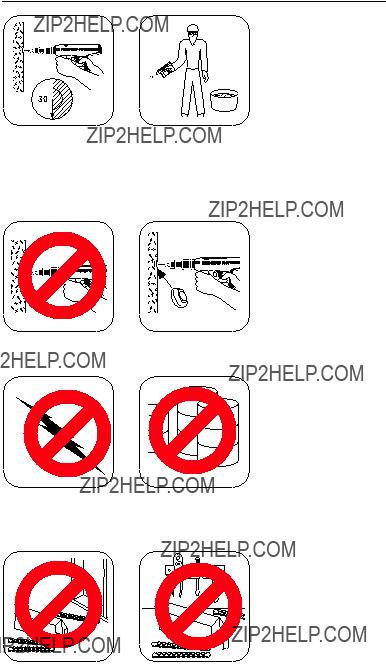
 Warning: Safety Precautions
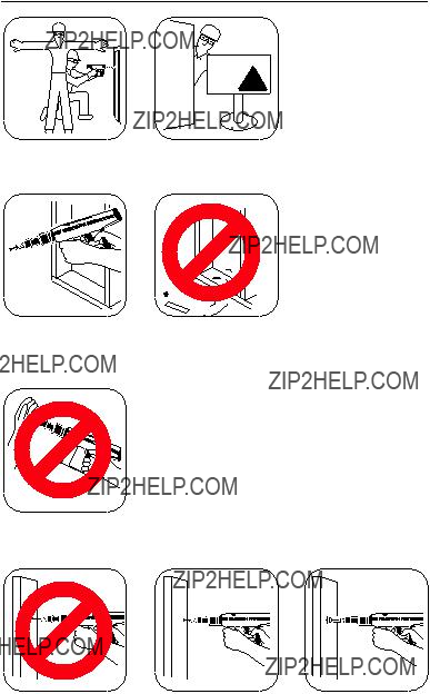

 LOADS
LOADS


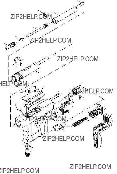
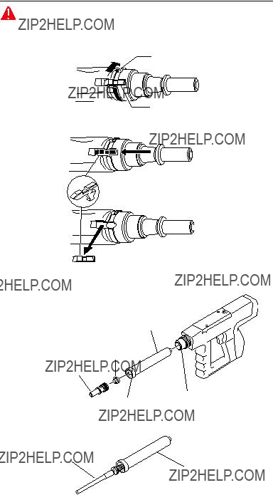
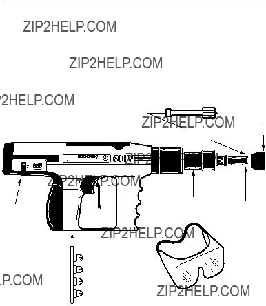
 Key Stop
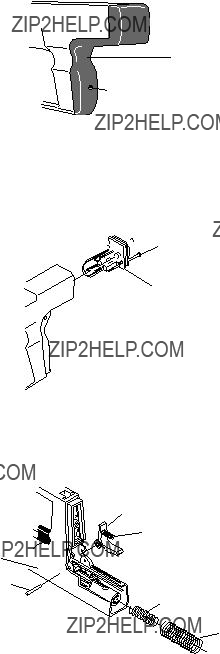
 3mm Hex Wrench
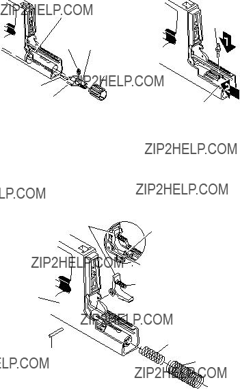
 Screws
 Housing
 Trigger


 Firing Pin Guide
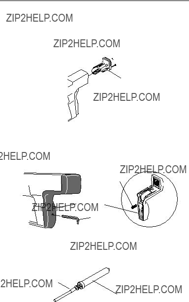

 Screws
 Housing
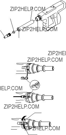
 Key Stop