IWAKI AMERICA
BELLOWS PUMP
INSTRUCTION MANUAL
IWAKI AMERICA
BELLOWS PUMP
INSTRUCTION MANUAL
Part Number 180138.C October 2007

1 INTRODUCTION
Thank you for selecting an Iwaki America
 CAUTION!
1.This instruction manual details the proper installation, operation and safety measures necessary to ensure the safe and efficient use of this pump. Failure to adhere to the described handling, installation and operating procedures may lead to malfunction or damage to the pump.
2.Always employ full safety measures and precautions when installing or servicing this type of pump based on the liquid being handled. Common applications are hazardous strong acids. Follow all safety procedures recommended by the chemical manufacturer.
3.To operate the pump, a controller system with adequate control and safety features is necessary. The pump always requires the use of a
4.Please ensure that the

2 UNPACKING AND INSPECTION
Open the package and check that the product conforms to your order. Also check each of the following points. For any problem or inconsistency, contact Iwaki America at once.
1.Check that the model number indicated on the nameplate conforms to the specifications of your order.
2.Check that the pump body and parts have not been accidentally damaged or that any fasteners have not been loosened in transit.
Figure 1
Iwaki America F Series Air Driven Bellows Pumps consist of a high purity virgin fluoroplastic pump head assembly with dual bellows and internal valving. A bellows is affixed on each side of the pump head assembly which houses the suction and discharge valves. A connecting rod and shaft system are mounted to the bellows and structural air chambers which seal against the pump head assembly. The bellows move reciprocally in the air chambers as a result of alternating pressurization of the air chambers, by which liquid is pumped continuously. Position of each bellows is monitored by proximity sensors mounted in the air chambers. Signals from the proximity sensors are used by the controller system to govern the
2
2.1Operation Sequence
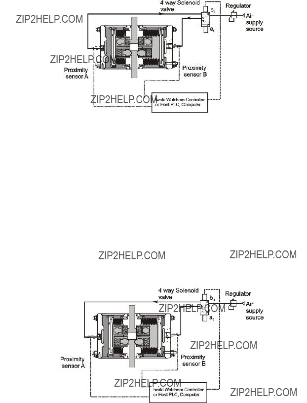
Figure 2
Refer to Figure 2. When pressurized air is supplied to chamber 'a' of the pump, bellows 'A' is compressed and fluid is discharged from the bellows through the pump head discharge (outlet) port. Simultaneously, bellows 'B' is extended and fluid is drawn into the bellows through the pump head suction (inlet) port. Air is being exhausted from pump chamber 'b' during this process. When bellows 'B' is fully extended, proximity sensor 'B' is activated to signal the completion of this stroke to the controller system.
The controller system receives the input signal from proximity sensor 'B' and changes the output signal to the
Refer to Figure 3. Once the
chamber 'b' of the pump and the process outlined above is reversed. Fluid is discharged from bellows 'B' while bellows 'A' is in its suction stroke and air is exhausted from chamber 'a.' Upon completion of this pump stroke, proximity sensor 'A' is activated and the controller signals the valve to switch from the b0 position to a0.
With a constant air supply, this sequence is repeated continuously and the pump achieves a constant flowrate based on installation and operating conditions.
Figure 3
3

2 IDENTIFICATION CODES
1 23
FA - 2E - W02
1.Series code: FA:
2.Maximum discharge volume: 0.5 Gal/min (2L/min)
3.Special specifications
3 SPECIFICATIONS
3.1
Note 1: The maximum discharge volume is based on pure water at 38??F (20??C).
Note 2: The
Note 3: In case of threaded type, 1/8 PT female threads.
4

3.2Proximity Sensor Specifications (for
5

3.3
Mass: 8.6 lbs (3.7kg)
Figure 4
6

4 HANDLING PRECAUTIONS
The following information deals with measures to ensure safe operation of the pump system. Please read the precautions carefully.
To operate this pump, a
4.1General Handling Precautions
???Do not remodel the pump:
Do not alter or modify the pump. Iwaki America takes no responsibility for accidents or damage that may result from improper modification of the product. Consult Iwaki America to discuss any alteration to the product.
???Do not touch:
When the pump is handling liquids higher than 50??C, avoid direct contact with the pump or piping system. Use appropriate hand protection if handling of the pump or piping is necessary.
???Wear protection:
Always wear protective gear (goggles, face shield, acid resistant gloves, etc.) when maintaining, removing or servicing the pump. In addition, flush the pump completely with DI water prior to any service or maintenance.
???Qualified operators:
Operation, service, maintenance and removal of the pump should be performed by trained personnel only.
???Disposal of used pump:
Disposal of used or damaged pumps must be in accordance with all federal and local regulations.
???Return to Iwaki America:
Contact Iwaki America prior to returning any product to discuss proper decontamination and return procedures. Iwaki America will issue a return authorization number to track the return. Note: Avoid cutting pump suction and discharge tubing. Leave existing fittings or adequate length of tubing to facilitate testing or evaluation.
7
4.2Pump Handling Precautions
???Do not stop pump without opening discharge first:
When stopping pump operation, first release pressure in the discharge line & then shut off supply air pressure. Residual pressure in the liquid discharge piping may result in deformation of the bellows due to the force of hydraulic pressure.
???Do not suspend operation for extended periods with liquid remaining in pump chamber: Suspending pump operation for extended periods may allow permeation of gas into air chambers & piping. This may cause corrosion of pneumatic components. To prevent this problem, purge air from the air chambers to prevent corrosive gas
???During pump operation:
Ensure suction or discharge line valves are fully opened during pump operation. Never close a suction or discharge line valve during operation.
???Pump at halt:
Do not supply air pressure to both air chambers simultaneously during operation or while the pump is idle. Some types of double solenoid valves cause pressurization of the two air chambers while the valve is idle. Do not use this type of valve with F Series pumps. Do not supply air pressure to either air chamber when the pump is idle.
???Lifting pump:
Do not lift the pump by the suction or discharge tubing while installing or removing the pump.
???Pump stroke speed:
Air bubbles sucked through pump suction piping could cause an air lock condition and the stroke rate to rise to an abnormal level. Safety measures should be taken to avoid running the pump above its maximum stroke speed. See page 11 for details.
80 spm............. 40 liter models
120 spm........... 2, 10, 20 liter models
???Supply air pressure:
Any fluctuation in supply air pressure or volume causes a change in pump discharge. Install a regulating valve to stabilize supply air pressure.
Regulate supply air pressure below maximum settings for longer life and protection of the bellows. Maintain differential pressure (supply air vs. discharge pressure) below 14 PSI (1 kg/cm2) to maximize pump service life.
???Liquid temperature range:
Temperature range of the liquid must be maintained within the specified temperature range for the pump model. (See Specification Table)
???Handle proximity sensor cables with care
When wiring or adjusting the sensor, take care not to twist or bend the cable excessively, as this may cause damage to the cable leads or the internal switch connection.
8
???Prohibited liquids:
The following liquids must not be used:
-Liquids that are easily crystallized
-Liquids containing slurry
-Solvent based fluids
Service life of the valve and bellows is shortened by liquids that are easily crystallized or contain slurry. Some solvents may cause premature failure due to incompatability with liquid end materials.
4.3System Safety Precautions
???Ventilate site:
When pumping a hazardous liquid, ventilating the cabinet is advised to remove toxic gas which may permeate components and build up inside the equipment.
???Monitor operating condition:
Use a monitor, etc. to inspect running condition of the system.
???Advance precautions:
Take advance precautions against pump or system abnormality and perform daily inspections.
???Use clean, dry instrumentation air (CDA) or nitrogen as supply air:
Supply air mixed with water, oil or dust may affect smooth and normal functioning of the pump. Excessive water in an air chamber may be detected by the leak detection sensor, leading to an alarm condition.
???Use an appropriate filter:
Select an appropriate filter for the pump, taking into consideration the filtering area,
???Do not restrict air exhaust port:
CAUTION! Do not restrict air exhaust piping of the pump or pneumatic system. Keep exhaust lines as short as possible. The bellows may be deformed as a result of excessive pneumatic backpressure. Quick exhaust valves are recommended.
???Pulse dampeners:
To reduce vibration in the liquid piping system or eliminate pulsation in the liquid flow stream, a full series of pulsation dampeners are available from Iwaki America.
9

4.4Liquid Circulation System Design Recommendations
In typical semiconductor wet process liquids, a catalyst such as H2O, O3 or H2O2 is added to the process
liquid. The subsequent reaction generates heat and produces extreme gassing of the liquid. Measures should be taken to reduce the amount of gas laden liquid which can enter the pump chambers. Excessive gas can cause an air lock condition for the pump which may increase the pump stroke rate to excessive levels.
For safe and efficient circulation and feeding of liquid, it is necessary to carry out air elimination and take proper safety measures.
Air elimination technique
When air enters the bellows and the pump becomes air locked, the pump stroke rate increases. If the increase is excessive, that is, higher than the specified pump stroke rate, stop the pump or carry out air elimination.
Plan A (Bubbles are blocked by means of a baffle plate)
1.In case of flooded suction system (Figure 5)
A baffle plate is set in the overflow tank to separate bubbles from the liquid, thus limiting the air content.
2. In case of suction lift system (Figure 6)
2. If the conditions under which bubbles are created remain the same, an air elimination technique which fits well with such conditions may be applicable. For example, if bubbles are generated only when feeding H202, open the auto valve to carry out air elimination only when H202 is fed.
10
Reaction
tank

3. Another technique is to install an air detection sensor in the suction port area, so that the auto valve is automatically opened by a signal sent out from the sensor and the air elimination operation is initiated.
5 INSTALLATION, PIPING & WIRING
5.1Installation
1.Pump installation position
???In case of flooded suction system, set the pump as close to the liquid supply tank as possible.
A flooded suction system is recommended for fluid recirculation or transfer applications above room temperature.
*
FLOODED
SUCTION
SYSTEM
Figure 8
SUCTION
LIFT
SYSTEM
???In case of suction lift system, set the suction side piping in accordance with the self- priming capacity and as close to the liquid supply tank as possible. (SeePage5)
2. Installation foundation
Select a flat and level rigid foundation (such as a chassis) for installation.
3.Direction of pump
???
???
???All other pump designs, FF,
*Note: The
11
5.2Piping
5.2.1 General
1.Carry out sufficient air blowing or flushing of tubing and connectors to remove foreign matter from inside surfaces prior to connecting them with the pump.
2.Tube connections should be done such that the extra load of piping is not applied to the pump, use pipe supports as necessary. Supports also prevent the vibration and heat generated along the piping from reaching the pump.
3.The connections on the piping should be assembled carefully, to prevent liquid leakage, air leakage, and air suction.
4.Commercially available connectors and tubing may be used in the piping system. However, for the liquid piping system, they must be designed to withstand leakage due to high temperature or heat cycle operation as well as corrosion from the liquid and atmosphere..
5.2.2 Liquid piping
1. Pump port diameters and materials
The standard material of the pump discharge and suction port is PFA tube. The applicable tube diameters are as follows:
Use tubing, piping and connectors with diameters corresponding to those of the pump tubes. The inside diameter of the piping connectors and tubing should be larger than those of the discharge and suction ports if possible. Never install connectors or tubing with smaller diameters than the pump suction and discharge tubing.
2.The length of the piping should be as short as possible. The number of bends, couplings and valves installed along the piping should also be minimized to keep the piping resistance as low as possible.
3.Design the piping to absorb linear expansion and thus prevent thermal stress onto the pump.
Points to be observed in suction pipe arrangement
1.The suction piping should be larger in diameter than the pump port if possible, and short in length. Iwaki America recommends the flooded suction system, if possible, for optimum performance. In the suction lift system, determine the height according to the
*The suction height differs with the liquid's characteristics, temperature & suction pipe length. For more detailed information, contact Iwaki America.
12

2. Install a filter or strainer with low piping resistance on the suction piping to block the entrance of solid particles or wafer fragments.
CAUTION! Wafer fragments inside the pump may get stuck in the bellows and cause damage. If solid matter clogs the pump's valves, internal suction or discharge volume may be affected with the normal checking function disabled.
3.When installing a valve on suction piping, select a valve with a larger orifice than the inner diameter of the pipe. A smaller orifice may result in a larger suction piping resistance or an increased chance for the valve to become clogged with a crystallized substance. Make sure to keep the valve open during pump operation.
CAUTION! Operating the pump with the valve on the suction piping closed will cause inward deformation of the bellows.
4. Do not create air traps in suction plumbing.
Points to be observed in the discharge piping arrangement
1.The pump discharge load increases with the length of the discharge piping and the number of bends along the pipe. Install a dampener to decrease the load and prevent pulsation.
2.When installing a valve on discharge piping, select a valve with a larger orifice than the inner diameter of the pipe. A smaller orifice may result in a larger discharge piping resistance or an increase chance for the valve to become clogged with a crystallized substance. Make sure to keep the valve open during pump operation. Do not close the valve until the discharge pressure is completely released after the pump is stopped.
CAUTION! Do not close the discharge valve to stop the pump. The resulting impactive pressure may deform the bellows.
3. A filter must be selected to meet the pump type. Filtering area,
CAUTION! The filter should be wetted before running process liquid. A desired flow rate may not be achieved if the filter is not wetted sufficiently. The filter dries out if the process liquid is not supplied for a long time. Read the filter instruction manual for details.
4.The piping should be designed so that no residual pressure results on the discharge side upon stopping the pump. (For example, filter air elimination should be set full open or a return circuit should be employed to remove residual pressure.)
CAUTION! Residual pressure in the discharge piping upon stopping the pump may deform the bellows.
13

5.2.3 Air Piping
It is critical that all pneumatic piping and components be sized according to the porting of the pump. Full port components with matching effective
1.Effective
For the effective
2.Determination of composite effective
Air devices are connected in series with the pump. It is necessary to determine the composite effective
Effective
3.Diameter of pump connection port:
The diameter of the connection port on the air supply side is as follows:
??? The inside diameter of the piping connectors and tubing should be larger than those of the pump
connection port, if possible. Never install connectors or tubing with smaller diameters than the pump.
14

2.Install a relief type regulating valve:
Fluctuation of supply air pressure results in fluctuation of the pump stroke rate as well as discharge volume. Install a regulating valve to maintain the air pressure at a fixed level. Select the regulator based on the air consumption rate of the pump. Pressure drop rating of the regulator should be less than 2.8 PSI (0.2 kgf/cm2).
3.Install a safety valve:
Install a safety valve after the air pressure regulator to prevent the supply air pressure from exceeding recommended maximum ratings.
4.Installation positions of regulating valve and
Install these valves as close to the pump as possible, in consideration of operating efficiency and pressure loss. Be sure to select valves that meet the air consumption rate of the pump. All pneumatic components should be full port, unrestricted style. Install solenoid valves in an area where vapors or liquids cannot harm them.
5.Installation of air exhaust port:
The exhaust ports of the air circulation system and the
CAUTION! Narrowing the air exhaust port may restrict the air exhaust out of the pump. As a result, the bellows may fail prematurely.
6. Measure to minimize air exhaust:
To minimize the noise of air exhaust, connect the exhaust port with a duct or attach a silencer on the exhaust port.
7.Installation of multiple pumps:
The total air consumption of pumps installed on a common air supply line must be considered to ensure adequate air volume/pressure supply. The diameter of the pipe must be determined taking into consideration the total number of pumps and total air consumption.
8. Recommended use of quick exhaust valve:
As shown in Figure 9, the air exhausted out of the pump flows out of the system via the exhaust port of the electromagnetic valve.
Depending upon the liquid handled, some permeated gas may be mixed into the exhaust air. (The inside of the
Note: The pump may be operated without quick exhaust valves, however air exhaust lines should be kept as short as possible with no restrictions to reduce piping resistance.
15

Figure 9
Pneumatic Piping/Control
16
5.4Wiring instructions
5.4.1 General
A. Extension of leak detector electrode wire:
Keep the resistance value at 5K ohms or below. A resistance greater than the above may make it impossible to detect a conductivity change between the leak detection electrodes. (This is dependent on the controller system.)
B.Wiring of proximity sensor:
Isolate the wires of the proximity sensor from the power line or other
5.4.2 For Use with Host PLC, Computer
Contact Iwaki America to discuss installation and wiring details for use with a PLC or host controller system. In general, the control system should provide the following pump and system features.
???Control of 5 port, 4 way solenoid valve for proper switching of air supply to pump
???High speed (overspeed) limitation protection
???Slow speed
???Leak detection alarm system (if applicable)
???Filter/air bleed system
The control system should ideally include these additional features:
???Pump stroke totalizer
???Pump stroke rate display (can be translated into flowrate display)
???Pressure monitoring and regulating system
???Slow speed
5.4.3Wiring for Iwaki America
For complete details for use with an
5.4.4 Wiring for
Connect the two wires from the
17

5.4.5 Wiring for proximity sensor
CAUTION! The proximity sensors of the F series pump have three leads. Faulty wiring may cause the proximity sensor to short circuit. Carry out the wiring carefully and accurately.
???Connect the leads of proximity sensor A with terminals 6, 7, and 8 respectively of the controller.
???Connect the leads of proximity sensor B with terminals 3, 4, and 5 respectively of the controller.
???Symbols A and B are arbitrary. The A and B may be interchanged. However, consistency between sensor and air supply lines is necessary.
WARNING! A standard proximity sensor cannot be used when a flammable liquid is used. Consult factory for details.
5.4.6 Wiring for Alarm Output 1
??? Connect with terminals 13 & 14 for use of the leak detection alarm circuit.
??? If the leak detection probes detect fluid in the pump air chambers, the circuit is closed. The red LED (bellows) indicator is illuminated, power to the solenoid valve discontinued and alarm output 1 is activated.
5.4.7 Wiring for Alarm Output 2
???Connect with terminals 11 and 12 for the use of the
???If the time set in the timer is exceeded due to suspended operation or reduced stroke rate of the pump, the yellow
18
6 OPERATION
Carry out the following preparatory steps when starting pump operation for the first time after installation or after a long suspension of the pump operation.
1.Confirm that all liquid connectors along the liquid piping system are fastened tightly.
2.Confirm that the valves on the suction and discharge piping (if applicable) are fully opened.
3.Confirm that the tank or bath has been filled with liquid. Allow the liquid to fill the entire piping system.
4.Confirm that the filter has been properly wetted. Follow the description in the filter instruction manual.
5.For initial installation
6.1Operation procedure
Following is a description of the operation and adjustment of the pump using the
6.1.2 Pump
1.Supply air to the pump by opening the supply valve. Adjust the air supply regulator to 14 PSI.
2.Turn on the power switch of the controller. The pump will start operation and the blue Operation indicator LED on the controller will start flashing.
3.Adjustment of pump speed and flow rate is ideally achieved by regulating the air volume supply to the pump via a bleed valve. Pump speed may also be adjusted by the air pressure regulator. Never exceed maximum settings for the specific pump model.
6.1.3 Pump stopping
1.Turn off the power switch of the controller.
The pump will stop operation and the 'Operation' indicator LED will go out.
2.Make sure the discharge side valve, if applicable, is open upon stopping the pump.
CAUTION! Do not close the discharge side valve to stop the pump.
3.Make sure the system does not allow residual pressure to remain on the discharge piping upon the stopping of the pump.
19

7 TROUBLESHOOTING
20

Iwaki America Inc.
5 Boynton Road Hopping Brook Park Holliston, MA 01746 USA TEL:
21