Ray430
Loudhailer
Owner???s Handbook
Ray430
Loudhailer
Owner???s Handbook
PURPOSE
THIS MANUAL CONTAINS IMPORTANT INFORMATION ON THE INSTALLATION,
OPERATION AND MAINTENANCE OF YOUR EQUIPMENT
Raymarine products are supported by a network of Authorized Service Representatives. For product information, you may contact the following regional centers:
United States?????????????????????????????????????????????. Raymarine, Inc.
21 Manchester Street Merrimack
New Hampshire
USA
Europe???????????????????????????????????????????????????.. Raymarine plc Robinson Way, Anchorage Park Portsmouth Hampshire P03 5TD United Kingdom
IMPORTANT NOTICE
THIS DEVICE IS ONLY AN AID TO BOATING SAFETY AND NAVIGATION. ITS
PERFORMANCE CAN BE AFFECTED BY MANY FACTORS INCLUDING EQUIPMENT
FAILURE OR DEFECT, ENVIRONMENTAL CONDITIONS, AND IMPROPER HANDLING OR
USE. IT IS THE USER???S RESPONSIBILITY TO EXERCISE COMMON PRUDENCE AND
NAVIGATIONAL JUDGMENT. THIS DEVICE SHOULD NOT BE RELIED ON AS A
SUBSTITUTE FOR SUCH PRUDENCE AND JUDGMENT.
TABLE OF CONTENTS
i
ii

SECTION 1
GENERAL DESCRIPTION
1.1INTRODUCTION
Congratulations on your purchase of the RAY430 Multifunction Loudhailer.
The RAY430 Loudhailer is a multipurpose device that may be used as a
As a loudhailer, the RAY430 amplifies your voice up to a 30 watt level, for hailing through the hailing horn speaker, and when listening for replies, amplifies the incoming sounds to the desired listening level. If an additional (optional) horn is added to the system, the loudhailer output can be switched to either or both of the hailing horn positions by the front panel control.
To verify your ownership and warranty registration, you should take a few minutes and fill out your warranty registration card found just inside the front cover of this manual. It is very important that you take the time to fill this card out. The warranty registration card should be returned to the factory immediately after your purchase in order to receive full warranty benefits.
Section 5 in this manual provides further information on obtaining Customer Service and Product Support which is available to you as a valued customer.
1.2EQUIPMENT FEATURES
The RAY430 is designed and manufactured to provide ease of installation and operation with excellent reliability. Some of the important
The loudhailer horns(s) are used as sound dispersal points when the RAY430 is used as a foghorn so that the full 30 watt output of the unit can be employed.
In the foghorn mode any of six programmed foghorn patterns can be automatically generated. They are: Underway, Stopped, Sail, Tow, Anchored, and Aground.
INTERCOM ??? Provides
AUXILIARY MODE ??? Allows the selective or simultaneous transmission of an external audio input to all stations. For entertainment, the external audio can be a cassette deck, radio, or CD player. For business, it can also be any other instrument having an external audio output, such as the output from a VHF or SSB radiotelephone.
EXTERNAL ALARM CONNECTION ??? For external systems or security alarm sensors.
EASY TO USE ??? An ideal arrangement, the RAY430 has an illuminated keyboard and LCD which clearly shows all selected stations and operating modes.
DURABLE, WATERPROOF CONSTRUCTION ??? With rugged gaskets and our
SILICONE RUBBER KEYBOARD ??? Has backlighting for easy
OPTIONAL
1.3SPECIFICATIONS

SECTION 2
INSTALLATION
2.1UNPACKING AND INSPECTION
Use care when unpacking your new RAY430 from the shipping carton to prevent damage to the contents. It is also a good practice to save the carton and the interior packing material. The original packing material should be used in the unlikely event that it becomes necessary in the future to return the unit for service.
2.2EQUIPMENT SUPPLIED
The following is a list of the standard equipment included with your RAY430 Loudhailer.

2.2.1 Optional Accessories
2.3STORAGE
After all of the components have been unpacked and inspected, they should be replaced in their shipping containers and stored in a dry place until they are to be installed. The storage area should be dry,

2.4PLANNING THE INSTALLATION
When planning the location for your RAY430 to be installed, the following conditions should be considered to insure dependable and
1)The mounting location should be easily accessible to allow easy operation of the front panel and provide the best viewing angle of the display.
2)There should be adequate ventilation.
3)A sufficient space should be secured behind the unit to allow all cable connections to the rear panel terminal strip.
4)The mounting place should be located as near to the power source as possible.
5)The selected location should be isolated away from devices that may cause offending noise or interference, such as motors, steering cables and generators.
6)Generally speaking, the Loudhailer should be protected from prolonged direct exposure to rain and salt spray. It is a good practice to protect this valuable equipment as much as pos- sible.
The unit can be conveniently mounted on a chart table, bulkhead, overhead or any other desired place. (Refer to Figure 2- 1 for typical locations and mounting configurations.)
Figure

Figure
2.4.1Mounting Options
Figure
2.5ELECTRICAL CONNECTION
Figure
CAUTION
DO NOT INSTALL THIS RADIO ON VESSELS WITH POSITIVE
GROUND BATTERY SYSTEMS.
2.5.1DC Power Connections
The RAY430 is intended for use on vessels with 12 VDC power systems and can operate as long as the DC supply is regulated between 10.8 and 16 VDC.
The input power connections are made at the terminal strip on the rear of the RAY430 unit at the terminals labeled "13.6V" "+" and

The power leads should normally be routed to the ship???s DC power distribution panel on larger boats. The RAY430 is fused at 10 amps so connection to a 10 amp or (maximum of) 15 amp circuit breaker is recommended. On smaller vessels the power leads may be connected directly to the main battery, isolation switch, or circuit breaker. For best noise isolation from other shipboard electronics avoid grouping the loudhailer power connections with radar, radio, or echo sounder power leads together on the same circuit breaker.
Although the RAY430???s power consumption is only 65 watts (maximum), if you find that the power cable leads need to be extended more than 10 feet, the wire size of the leads should be
Observe proper polarity! The wire connected to the positive (+) terminal must be connected to the positive point of the DC power source; The wire connected to the Negative
2.5.2Intercom Speaker
Up to four intercom station speakers (optional) can be connected to the intercom speaker terminals labeled
Connect one of the speaker lines to terminal 2, the other line to the GND terminal (on the right side of the terminal block). The ???call??? line should be connected to the terminal 1.
Figure
2.5.3Hailer Horn(s)
The outside hailer horns should be mounted facing away from the display unit to prevent feedback problems using the universal swivel mount provided. High gain audio amplifier circuits ???hailers??? are susceptible to high frequency audio oscillations (a.k.a. feedback). It is highly recommended that be- fore permanently mounting the hailing horn, that the HAIL feature is tested with the horn in the desired location. This should be done to ensure optimum performance. Generally speaking the horn should be mounted as far away as possible and facing away from the RAY430 base unit. It should be pointed in the opposite direction of the RAY430 microphone as you are speaking into it.
Connection to the horn(s) should be made with No. 1 8 or larger, stranded, twisted pair copper wire. The
Electrical connections from the deck horn(s) are made on the rear panel terminal strip at either the FWD or AFT terminal point, depending on the location of the speaker you are connecting.
For connection to FWD, connect the deck horn to terminals ???FWD??? 1 and 2. For connection to AFT, connect the deck horn to terminals ???AFT??? 1 and 2.
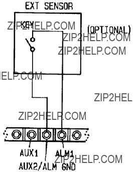
2.5.4Connection of Burglar Alarm
By connecting an external alarm sensor using a normally open type of switch (not supplied) to the ALM terminals, this unit can be used as a burglar alarm in the Fog ALM mode (burglar alarm).
When the sensor connected at terminals 1 and 2 (AUX) of this terminal block become shorted (closed), the alarm function becomes activated and the yelp signal will sound at the maximum volume through the forward deck hailer horn speaker.
Figure
2.5.5 Remote Microphone
An external microphone connection is located on the rear panel terminal strip. This may be used if you desire to operate hailing functions from a secondary station.

Figure
2.5.6 Auxiliary Input
Your RAY430 has been designed to allow you to amplify the audio from your VHF radiotelephone or any other external audio output (i.e. AM/FM radio, CD player) through your intercom or deck speaker stations. This external audio input can be connected at the auxiliary input terminals 1 and 2.
2.5.7Connection of an External Speaker
In situations where the main unit is distant from the operator and the noise level is very high, it may be difficult to hear your RAY430 clearly. By connecting an external (8 ohms, 5 watts or more) speaker, the sound level can be increased for improved listening capability. When an external speaker is connected at the external speaker jack, the internal speaker is automatically disconnected. The connector, a mini phone plug, for the external speaker is supplied with your RAY430 for your convenience.

Figure
SECTION 3
OPERATION
3.1INTRODUCTION
While the operation of the RAY430 is easy and straight forward, the operator who is familiar with the functions and understands the layout of the front panel controls will be able to obtain the best performance from their equipment.
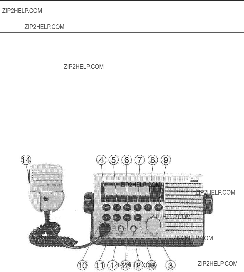
Following is a description of the front panel controls of the RAY430 loudhailer.
3.2CONTROLS AND LCD DISPLAY
Refer to Figure
Figure
3.2.1Controls
1)On/Off & Dimmer Control Knob:
This control turns the RAY430 On and Off, and rotating the control clockwise increases the backlighting level of the LCD display.
2)Hail Output Control:
Rotating this control clockwise will increase the volume going to the Hailer Horns or
3)Listen Control:
Rotating this control clockwise will increase the listening volume at the internal speaker and rotating this control counterclockwise will decrease the volume.
4)Hail Key:
Pressing the [HAIL] key puts the RAY430 into the hailer mode and HAILER is displayed on the LCD.
5)FOG (Foghorn) Key:
Pressing the [FOG] key sequentially selects one of the 9 different horn or automatic fog signals for use.
6)AUX (Auxiliary) Key:
Audio signals connected to the AUX input from radiotelephone, tape player, etc. are amplified and heard at the selected external speaker location(s).
7)IC (Intercom) Key:
Pressing this key puts the RAY430 into the Intercom mode.
8)IC 1/2 Key:
Selects between Intercom Station 1 or 2 for connection to the input/output circuitry in the Intercom Mode. Pressing the [IC 1/2] key, selects IC- 1 ,
9)IC 3/4 Key:
Selects between Intercom Station 3 or 4 for connection to the input/output circuitry in the Intercom Mode. Pressing the [IC 3/4] key selects
10)FWD (Forward) Key:
Selects the Hailer horn which is normally mounted on the forward part of the vessel for use as a foghorn, hailer or public address system.
11) AFT (After) Key:
Selects the Hailer horn which is normally mounted at the rear of the vessel for use as a
12) BOTH Key:
Selects both Hailer horns which are mounted on the forward and rear part of the vessel for simultaneous use as foghorns, hailing or for public address.

13)ALL Key:
Connects the input/output circuitry to all speaker stations for use simultaneously during
14)Microphone PTT
The PTT switch located on the side of the RAY430 microphone is used to activate the microphone, etc.
3.2.2LCD Display
The custom LCD display on the RAY430 is used to show the operation status of the loudhailer in bright bold characters. The display is illuminated in a
The Ray430 has 4 operating modes. The selected mode is indicated by the message on the left side of the display. The modes messages are:
HAILER ??? for Hailing or public address mode
INTERCOM ??? for Intercom operation on up to 4 different stations
SEE TABLE ??? for Fog horn Signal mode. The RAY430 generates any one of 9 automatic or manual fog horn signals.
AUX ??? for Auxiliary audio inputs.
Figure
When the FOG mode is selected, the message area will display the selected type of signal to be emitted as follows:
The speaker station display normally indicates the location of the speakers selected for use with each operating function. Located on the top right side of the display these messages use up to four characters. The speaker stations are: FWD, AFT, BOTH, or ALL.
In the FOG mode, the speaker station message area will temporally indicate which FOG mode # has been selected for use when the [FOG] key is pushed. One second later the normal speaker station selection message will
When the microphone
Further information on the operating modes can be found in the sections that follow.
3.3OPERATING PROCEDURES
Specific operating procedures for the RAY430 are explained in this section. Refer to the Controls section 3.2. 1 beginning on page
3.3.1 The ???Power Switch / Dimmer Control???
The On/Off & Dimmer control knob is used to turn on the Power, then controls backlighting levels.
TURNING THE UNIT ???ON???
Rotate the On/Off & Dimmer control knob clockwise to turn the unit on. The display will appear in about 1 second. Now, set the On/Off & Dimmer Control knob to your desired backlighting level.
TO TURN THE UNIT ???OFF???
Rotate the On/Off & Dimmer control knob counterclockwise to turn the unit off. The display will disappear immediately and the backlighting will be extinguished. The unit will now be OFF.
Note: You should never remove the power leads while the unit is turned on.
3.3.2Volume Control (Hail & Listen)
1)HAIL Volume
Controls the volume level to external loudspeakers connected to the RAY430.
2)Listen Volume
This allows the user to Adjust the RAY430 to the desired listening volume level. When the control is turned clockwise, the volume level will increase. The volume level decreases when the control is turned counterclockwise.

3.3.3Hail Mode
The mode keys are used to select one of the four operating modes. They are HAIL, FOG, AUX or INTC.
To operate the RAY430 as a loudhailer, proceed as follows:
1.Press the [HAIL] key.
After pressing the [HAIL] key, the HAIL mode is selected and ???HAILER??? appears on the LCD display in the operating mode window. In general, ???Hailing??? is normally performed using the forward hailing horn speaker. However, you can select the AFT horn speaker (if connected) or ???Both??? or ???All??? speakers (which includes intercoms) for general ships announcements.
2.Press the desired speaker key to select the FWD, AFT, BOTH or ALL positions as required for your particular application. Your selection appears in the speaker station window on the top right of the LCD display.
3.Press the microphone???s PTT button and speak into the microphone. Now, adjust the HAIL volume as required using the Hail knob.
In HAIL mode, upon pressing the microphone [PTT] button, ???TALK??? appears in the speaker window. Your voice signal is amplified through the microphone and is sent to the selected external speaker(s).
Releasing the microphone [PTT] button, ???TALK??? disappears from the speaker station display window and the speaker station name
3.3.4Intercom Operation
In general, the intercom mode is used to communicate with one of the intercom stations installed on the vessel. So if intercom operation is desired, you must first:
1.Press the [IC] key. ???INTRCOM??? will appear on the LCD display in the operating mode window.
2.Set the STATION ([IC 1/2], [IC3/4]) key to the desired intercom station.
Selection of the desired intercom station by pressing the appropriate station key is the second step in

operating the intercom mode. Once the station has been selected, communications from the master station (RAY430 unit) can be enabled.
In the intercom mode, upon pressing the microphone [PTT] button, ???TALK??? appears in the speaker station display window. Your voice signal through the microphone is amplified and sent to the Selected intercom speaker(s).
When the [PTT] button is released, the speaker at the selected station location can act as a microphone, with sounds being heard at the RAY430 internal speaker or external speaker (if connected). The RAY430 microphone takes priority over any responses from intercom
Both the HAIL and LISTEN controls can be adjusted for desired volumes by rotating the Hail or Listen volume control knobs.
Marking calls from Remote Intercom Stations
As long as RAY430 power is on, the RAY430 master station can be called from any of the
When the [CALL] switch on the
The RAY430 allows you to connect a maximum of four intercom station speakers. The remote intercom stations cannot communicate directly with each other.

3.3.5Fog Horn Mode
The [FOG] key allows the user to alternately select one of the automatic or manual FOG output signals. There are 9 kinds of alarms. They are: MANUAL, UNDRWY, STOP, SAIL, TOW, ANCHOR, AGROUND, YELP and ALARM. Whenever the [FOG] key is pressed, the alarm type is changed in the following order:
A.MANUAL ??? This lets the hailer serve as a horn for the vessel to permit manual horn signals as described in the ???Rules of the Road??? - Section 35.
Usage: Passing Signals, etc.
???MANUAL??? appears in the mode display window.
In this mode, the horn sounds when you press the microphone [PTT] button. The length and timing of the horn blasts are controlled by depressing the
Example:
B.UNDRWY (Fog 1) Usage: Power Boat ???UNDERWAY???
This is a programmed automatic fog signal for powered vessels underway. The message ???UNDRWY??? appears on the mode display window. While operating the [FOG] key, ???FOG 1 appears on the station display window for reference.
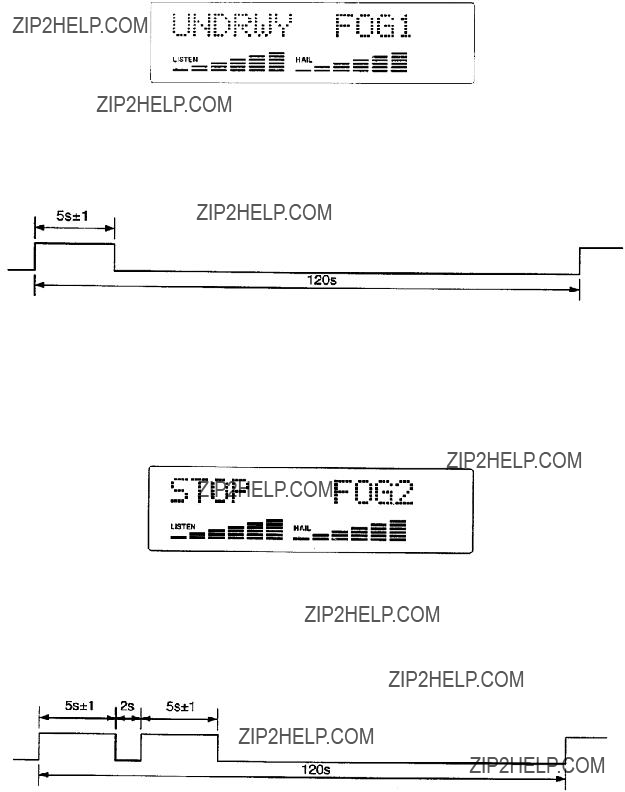
In 1 second, ???FOG 1 ??? disappears and the station speaker selection appears.
The Fog 1 alarm pattern is: One
C.STOP (Fog 2) Usage: Power Boat ???STOPPED???
This automatic fog signal is emitted when the vessel is stopped. The message ???STOP??? appears in the mode display window and ???FOG 2??? appears in the speaker station display window momentarily.
???FOG 2??? disappears and the speaker station
The FOG 2 signal pattern is: Two
D.SAIL (FOG 3) Usage: Sail Boat, Fish Boat, Tow Boat
This automatic fog signal is used for sail boats, fish boats and tow boats underway. ???SAIL??? appears on the mode display part and ???FOG 3??? appears in the station display window when you press the [FOG] key.

???FOG 3??? will disappear and the speaker station selection
The Fog 3 signal pattern is:
One 5 second blast, followed by two I second blast, at 2 second intervals, this will be repeated every 2 minutes.
E.TOW (FOG 4) usage: Vessels Under Tow
When you press the [FOG] key again this automatic fog signal is selected, the message ???TOW??? appears in the mode display window and ???FOG 4??? is temporarily displayed in the station display window.
???FOG 4??? will disappear and the speaker station name
The FOG 4 signal pattern is:
One 5 second blast, followed by three 1 second blasts, at 2 second intervals, this will be repeated every 2 minutes.
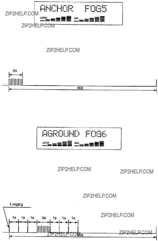
F.ANCHOR (FOG 5) Usage: Any Vessel at Anchor
For this automatic fog signal press the [FOG] key again, the message ???ANCHOR??? appears on the mode display and ???FOG 5??? appears in the station display window.
???FOG 5??? will disappear and the speaker station reappears in 1 second after FOG 5 is selected. The Fog 5 signal pattern is:
A rapidly ringing bell tone will sound for a duration of at least 5 seconds, with a repetition interval which will not exceed 1 minute.
G.AGROUND (FOG 6) Usage Any Vessel Aground
When you press the [FOG] key again this automatic fog signal is selected ???AGROUND??? appears in the mode display window and ???FOG 6??? appears in the station display window.
???FOG 6??? will disappear and the station name reappears 1 second after completing the selection.
The Fog 6 signal is:
Three bell tones sound at one second intervals, followed by a rapidly ringing bell tone for a duration of 5 seconds, followed again by three bell tone sounds at one second intervals. This is repeated once every minute.
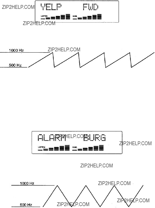
H.YELP Usage: Coast Guard, Patrol Vessels, etc.
This is a manually activated attention getting alarm signal often used by regulatory vessels. When the [FOG] key is pressed again Yelp is selected, ???Yelp??? appears in the mode display window.
In this mode the horn yelps by pressing the microphone PTT button.
I.ALARM (Burglar alarm mode)
If an external normally open type switch sensor is attached (not supplied) to the ALM terminal on the rear panel, this unit can operate as a burglar alarm unit.
When the FOG mode key is pressed until ???ALARM??? appears on the mode display part and ???BURG??? appears on the station display window, the burglar alarm mode is enabled.
Within a few seconds ???BURG??? disappears and forward horn speaker station name appears.
The Burglar alarm signal is a ???warble??? type of signal similar to the yelp signal.
When the Burglar alarm mode is selected, the speaker station is changed to FWD, and the HAIL volume is set to the maximum level automatically.
The alarm itself is not enabled for five minutes after selection. However, in five minutes, the characters and backlighting on the LCD display window goes out and only the [FOG] key and On/Off & Dimmer Control (to Off) are operable on the RAY430. The RAY430 will appear to be OFE In this condition the burglar alarm will only sound if the ON signal from the external alarm sensor connected to the ALARM is tripped.
Clearing the ALARM mode
To disable the Burglar alarm mode, press the [FOG] key or turn off the RAY430 by rotating the On/Off & Dimmer control knob fully counterclockwise.
3.3.6 Aux Mode
If the audio output line from a radiotelephone equipment, cassette deck, or entertainment receiver is connected to the AUX terminals 1 and 2, the output signals of such units can be amplified through desired speaker stations by the RAY430.
1.Press the [AUX] mode key which will enable the auxiliary mode.
2.Press the desired speaker station key to select the specific station ([IC 1/2], [IC 3/4]).
3.Adjust the HAIL volume for the desired listening level.
SECTION 4
TECHNICAL DESCRIPTION
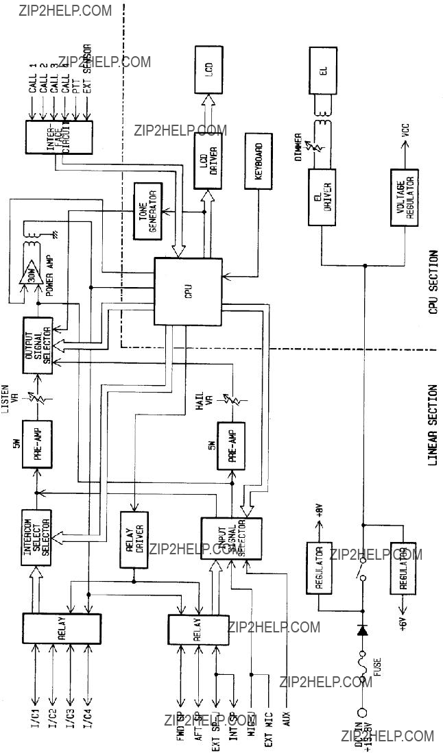
4.1BLOCK DIAGRAM
Figure
1.1. CPU
The CPU
2.Relay
Changes input/output signals and is controlled by the CPU.
3.Relay Driver
Selects the input and output speakers
4.5W
IC2 and IC3 amplifies low level voice signals and supplies them to the output signal selector through Listen Volume VR 1.
5.Intercom Selector
Activates the Intercom speaker with selected keyboard or Call key.
6.Output Signal Selector
Select the output signal (Foghorn Signal, Intercom, Alarm or Mic input signal) to the Power Amplifier
7.Power Amplifier
IC1 is a 30W power amplifier to active the selected speaker.
8.Interface Circuit
Senses the ???CALL??? or alarm sensor signals from the external unit. The photo couplers are used to reduce any external noise pickup by isolation.
9.Input Signal Selector
Selects input signal to active the FWD, AFT, INT, or EXT speaker(s).
10.10. Tone Generator
Generates a horn and alarm sound for the RAY430. This generator is controlled by the CPU to produce correct sound patterns and signal timing for various automatic or manual signal outputs.
11.LCD Driver
12.12. LCD
The LCD is a custom LCD featuring 1 2 characters on a Dot Matrix display. The bar for the volume and the intercom call numbers are displayed with 16 segment x 8 characters.
13.EL Driver
Drives the EL, controlled by On/Off & Dimmer control knob.
14.EL
Backlights the LCD display.
Figure

SECTION 5
MAINTENANCE
5.1GENERAL
The purpose of this section is to provide servicing instructions to the service technician. The RAY430 is designed to provide long periods of
5.1.1 Product and Customer Service
In the event that your RAY430 is in need of service, the dealer from whom the radio was purchased, or an authorized Raymarine dealer.
Our Technical Support Specialists are also available to answer installation, operation, and trouble shooting questions about your RAY430. In the US, contact our Technical Support Department Monday to Friday 8:15 AM to 5:00 PM Eastern Time at:
Many Raymarine accessory items and parts are available through your authorized Raymarine dealer. However, if you are in need of an item not available through your retailer, please contact our Customer Service department Monday to Friday 8:15 AM to 5:00 PM Eastern Time at:
In Europe, Raymarine support, service and accessories may be obtained from your authorized dealer, or call:
+44 (0) 9269 3611
5.2PREVENTATIVE MAINTENANCE
The procedures listed below for the RAY430 should ideally be performed at monthly intervals to minimize the possibility of an equipment failure and assure optimum performance.
1.Fuse holders and their connections may be subject to corrosion which can increase circuit resistance. The
2.The unit front panel should be cleaned with a tissue or a soft
CAUTION
Do not use solvents or other chemicals for cleaning this equipment.
5.3ADJUSTMENT
The RAY430 has been completely aligned at the factory and normally does not require any readjustment at installation. However, it is possible to adjust the tone level of the Hail & Intercom signal.
5.3.1Test Equipment
1 Audio Oscillator
2 AC SSVM
3
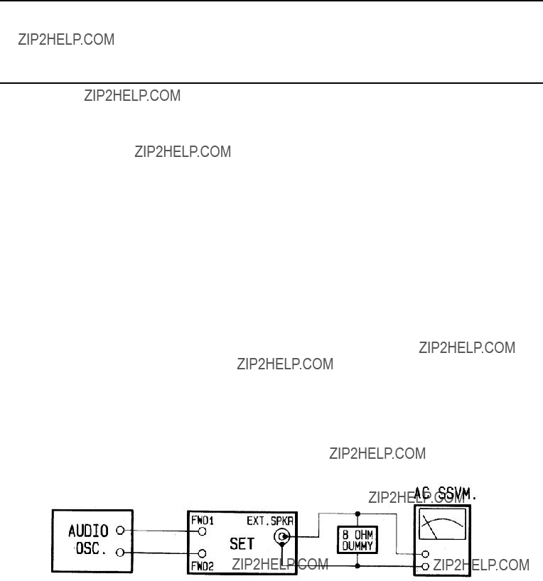
5.3.2Listen Output Adjustment
Connect Audio Oscillator, AC SSVM and
Rotate the Listen Volume fully clockwise.
Adjust VR301 for 6 V on the AC SSVM.
Figure 5- 1 Test connection for Listen output Adjustment
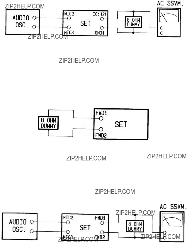
5.3.3Intercom Output Adjustment
Connect Audio Oscillator; AC SSVM and
Rotate Hail Volume fully clockwise. Adjust VR302 for 6V on the AC SSVM.
Figure 5- 2 Test connection of Intercom output Adjustment
5.3.4Level Meter Adjustment
Connect
Select Manual Fog operation Mode.
Press the PTT switch and adjust VR101 to show 6 bars progressing from left to right on the LCD.
Figure 5- 3 Test connection of Intercom output Adjustment
5.3.5Hailer Output Adjustment
Connect Audio Oscillator; AC SSVM and
Rotate Hail Volume fully clockwise. Adjust VR303 for 15.5V on the AC SSVM.
Figure 5- 4 Test connection of Hailer output Adjustment

SECTION 6
6.1PARTS LIST
*****LINEAR A PCB ASSEMBLY SECTION *****
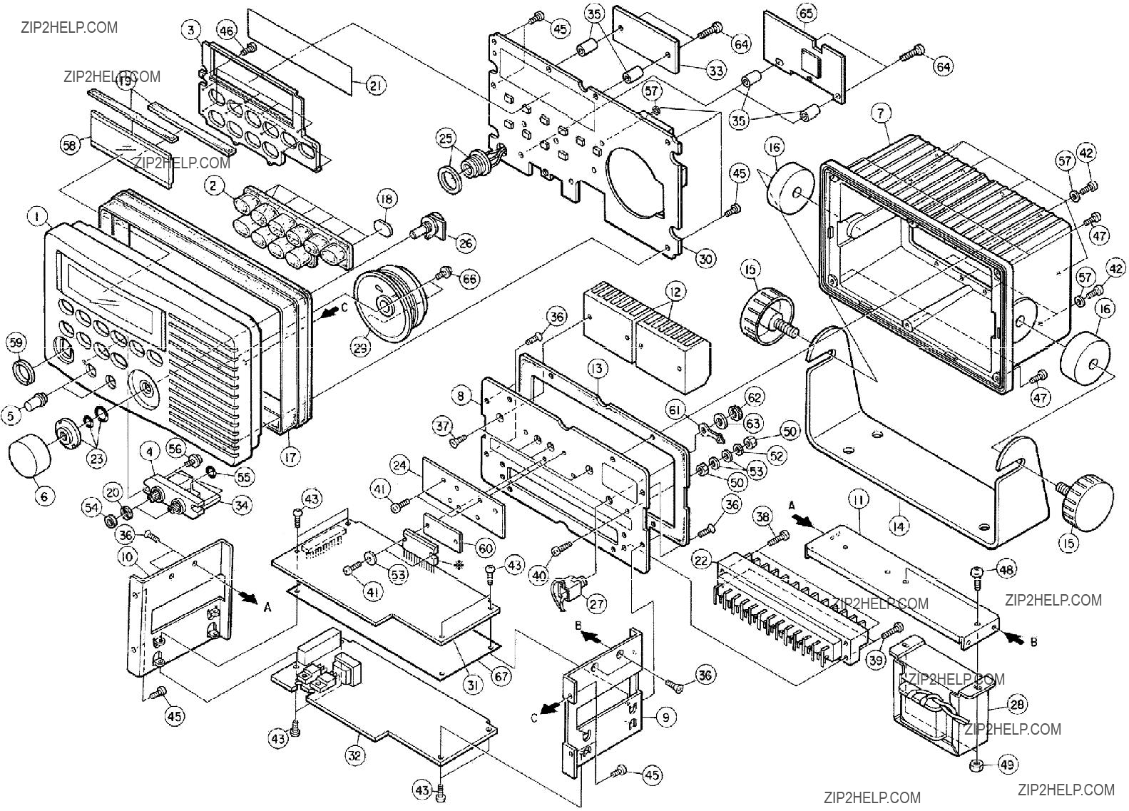
6.2 ASSEMBLY DRAWING
6.3 PARTS LIST for ASSEMBLY DRAWING
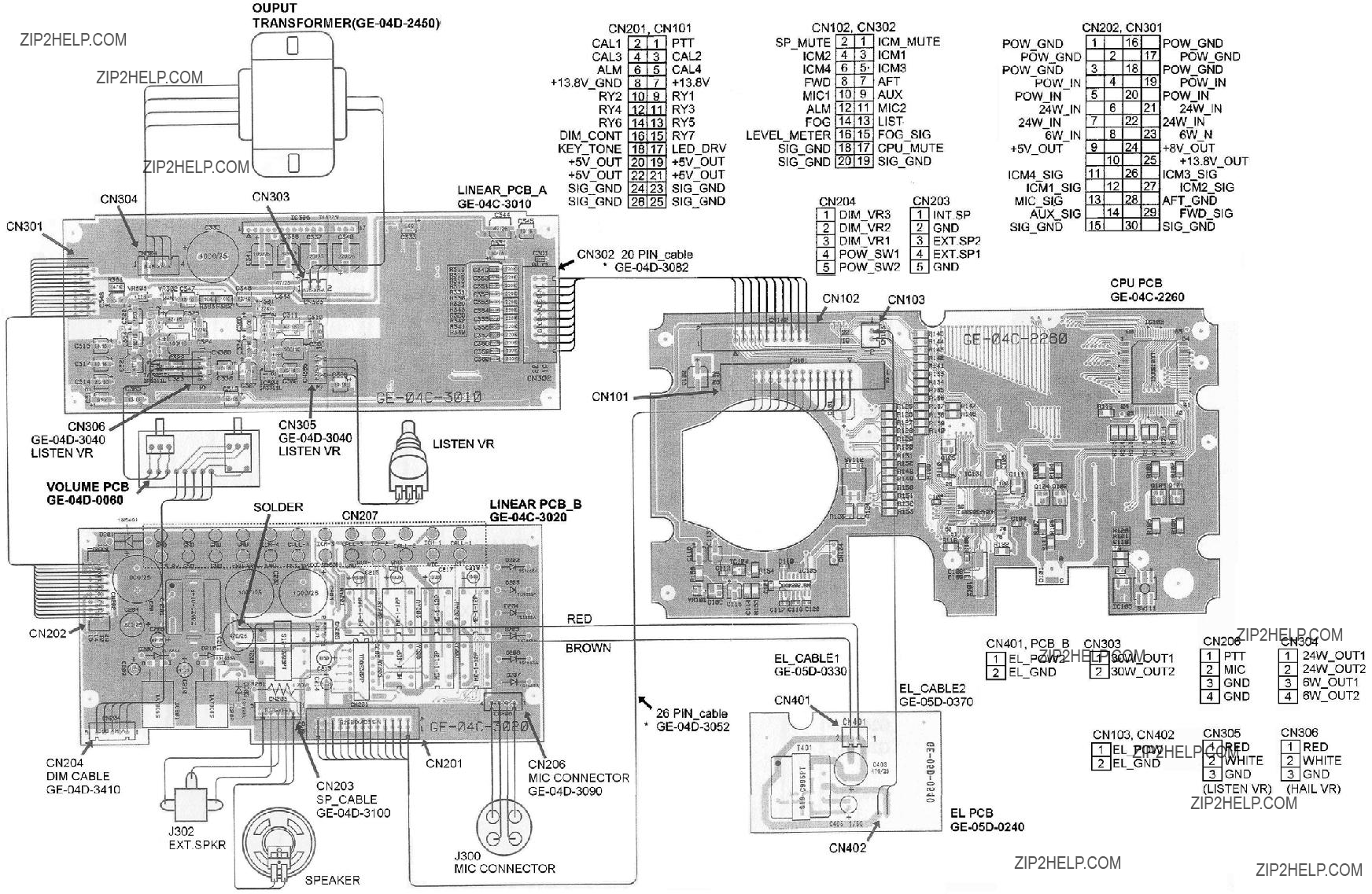
6.4 INTERNAL WIRING DRAWING
6.5 LINEAR A SCHEMATIC DIAGRAM
Figure
Schematic Diagram
(Linear A Section)

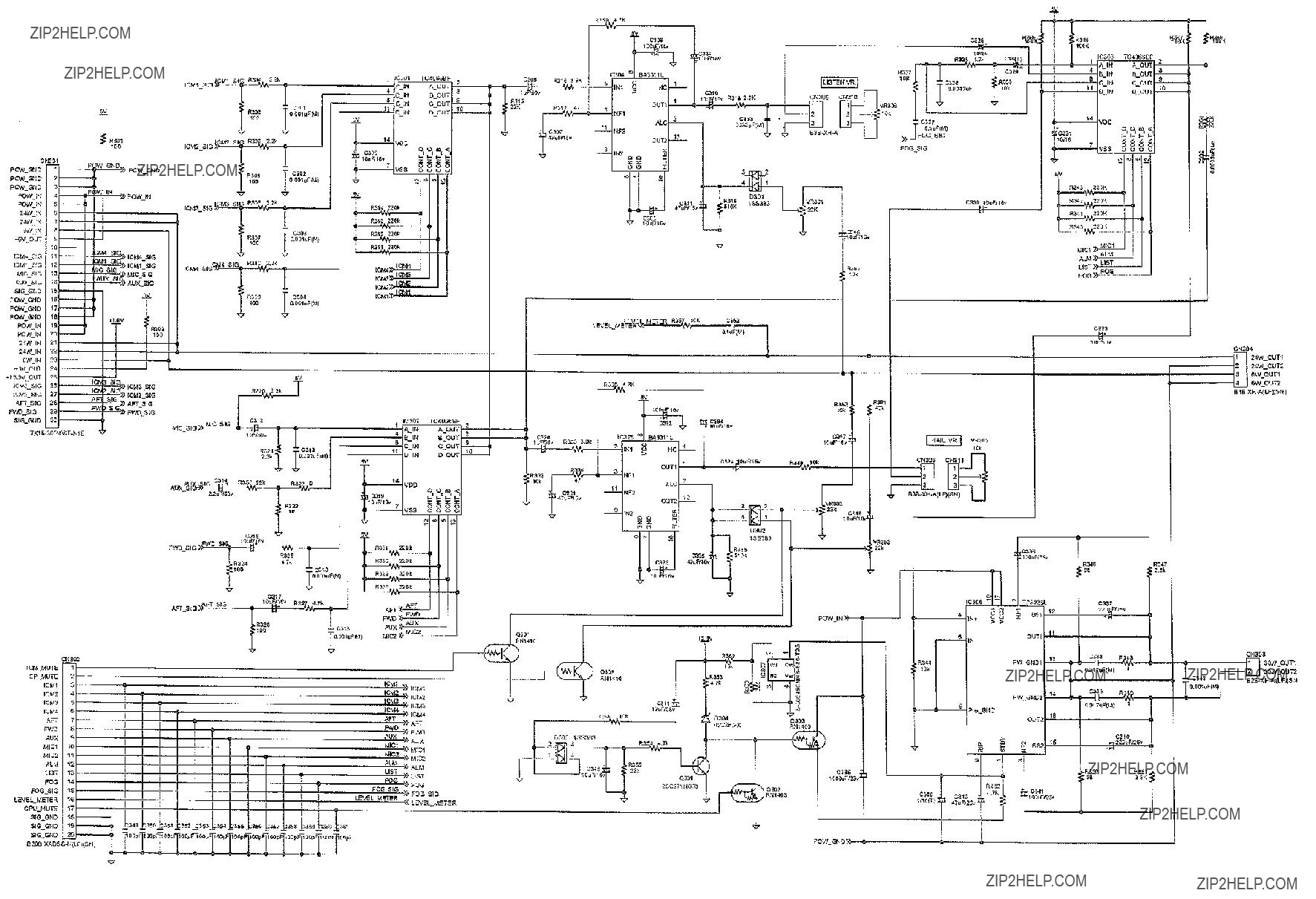
6.6 LINEAR B SCHEMATIC DIAGRAM
Figure
(Linear B Section)
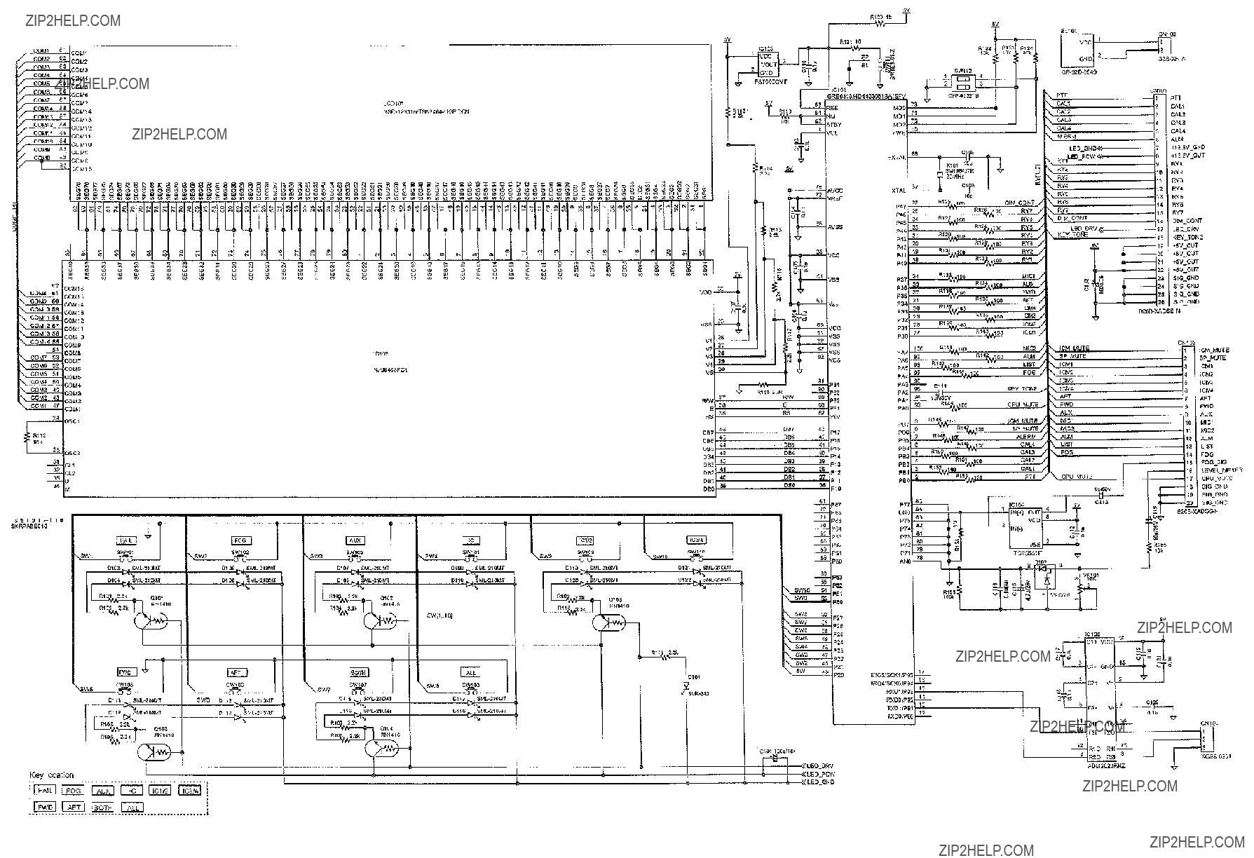
6.9 CPU PCB SCHEMATIC
Figure
(Main Section)
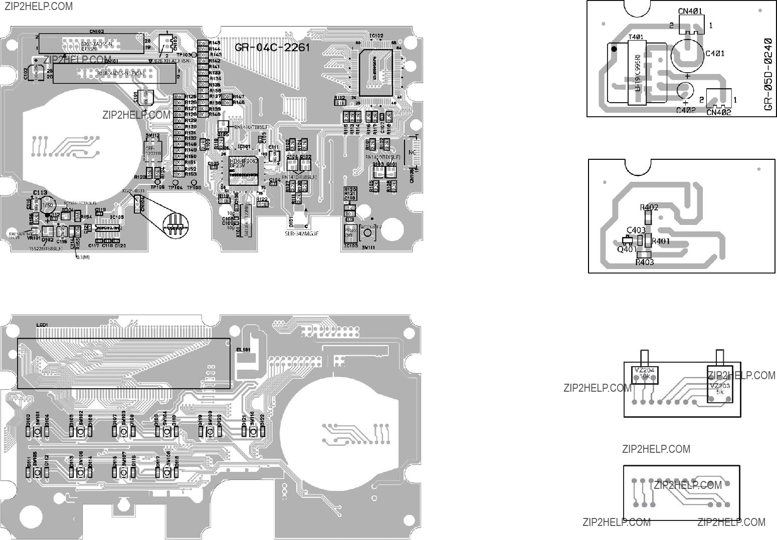
6.10 CPU PCB PARTS LAYOUT
TOP VIEW
TOP VIEW
BOTTOM VIEW
Figure
EL PCB
Parts Layout
TOP VIEW