M1500 Marine
Monitor
Owner???s
Handbook
Document number: 81208_1
Date: June 2003
Raymarine is a registered trademark of Raymarine Limited.
i
M1500 Marine Monitor Preface
This handbook contains very important information on the installation and operation of your new equipment. In order to obtain the best results in operation and performance, please read this handbook thoroughly.
Raymarine???s Technical Services representatives or your local dealer will be available to answer any questions you may have.
Important information
Intended Use
This display is intended to be used in a recreational marine environment. It can be integrated as part of a marine navigation system and/or used within an entertainment system.
Safety notices
WARNING:Product installation
This equipment must be installed and operated in accordance with the Raymarine instructions provided. Failure to do so could result in poor product performance, personal injury and/or damage to your boat.
WARNING: Electrical safety
Make sure you have switched off the power supply before you start installing this product.
WARNING: High Voltage
The display unit contains high voltages. Adjustments require specialized service procedures and tools only available to qualified service technicians ??? there are no user serviceable parts or adjustments. The operator should never remove the display unit cover or attempt to service the equipment.
WARNING: Navigation aid
When this display is used within a navigation system, it is only an aid to navigation. Its accuracy can be affected by many factors, including equipment failure or defects, environmental conditions, and improper handling or use. It is the user???s responsibility to exercise common prudence and navigational judgements. This unit should not be relied upon as a substitute for such prudence and judgement. Always maintain a permanent watch so you can respond to situations as they develop.
CAUTIONS:
1.To disconnect the display from the ship???s supply isolate the power cable from the main supply or remove the power connector from the rear of the monitor. Note that the ON/ OFF button at the front of the monitor changes the operating mode; it does not provide complete protection in an emergency.
2.To avoid risk of electrical shocks, use only Raymarine specified cables.
3.To prevent damage caused by lightning or abnormal current peaks, disconnect the dis- play from the power source during intense storms, or when it is not being used for long periods of time.
4.Call a qualified service engineer if any of the following occur:
i.The power cable or signal cable is damaged or worn.
ii.Liquid has penetrated the monitor.
iii.The monitor is not working correctly despite the fact that it has been used follow- ing the instructions provided.
iv.The monitor has been dropped or the casing has been damaged.
v.There is a major deterioration in the monitor???s performance.
TFT Color LCD Displays
The colors of the display may seem to vary when viewed against a colored background or in colored light. This is a perfectly normal effect that will be seen with all color LCD displays.
In common with all Thin Film Transistor (TFT) LCD displays, the screen may exhibit a few (less than 20) wrongly illuminated pixels. These may appear as black pixels in a light portion of the screen, or as colored pixels in black areas.
CAUTION:
To provide protection against the damaging effects of UV light, it is advisable to replace the sun cover provided when the color LCD display is not in use.
EMC conformance
All Raymarine equipment and accessories are designed to the best industry standards for use in the recreational marine environment. The design and manufacture of Raymarine equipment and accessories conform to the appropriate Electromagnetic Compatibility (EMC) standards, but correct installation is required to ensure that performance is not compromised.
Handbook information
The technical and graphical information contained in this handbook, to the best of our knowledge, was correct as it went to press. However, our policy of continuous improvement and updating may change product specifications without prior notice. As a result, unavoidable differences between the product and handbook may occur from time to time.
Raymarine cannot accept liability for any inaccuracies or omissions it may contain.
For the latest product information visit our website:
www.raymarine.com
Warranty
To register your new Raymarine product, please take a few minutes to fill out the warranty card. It is important that you complete the owner information and return the card to the factory to receive full warranty benefits.
Technical Support:
To access the Raymarine Questions & Answers database, service information, new product information and e-mail access to the Technical Support department, please visit our website at:
www.raymarine.com
iii
Alternatively, if you don???t have access to the world wide web, contact technical support as detailed below. Our Technical Support Specialists are available to answer questions about installing, operating and trouble-shooting all Raymarine products.
How to Contact Raymarine (US)
For Accessories and Parts
Many Raymarine accessory items and parts can be obtained directly from your local authorized Raymarine dealer. However, if you are in need of an item not available from the retailer, please contact Raymarine Technical Services at:
1-800-539-5539 extension 2333 or (603) -881-5200.
Technical Service is available Monday through Friday 8:15 am to 5:00 pm Eastern Standard Time or Eastern Daylight Savings Time.
Please have the Raymarine item or part number ready when calling if placing an order. If you are not sure which item is appropriate for your unit, you should first contact the Technical Support Department at:
1-800-539-5539 ext. 2444 or (603)-881-5200 to verify your requirements.
For Product Repair and Service
In the unlikely event your Raymarine unit should develop a problem, please contact your authorized Raymarine dealer for assistance. The dealer is best equipped to handle your service requirements and can offer timesaving help in getting the equipment back into normal operation.
In the event that repairs can not be obtained conveniently, product service may also be obtained by returning the unit to:
Raymarine Product Repair Center
22 Cotton Road, Unit D
Nashua, NH 03063-4219
The Product Repair Center is open Monday through Friday 8:15 a.m. to 5:00 p.m. Eastern Standard Time or Eastern Daylight Savings Time. All products returned to the Repair Center are registered upon receipt. A confirmation letter will be sent to you acknowledging the repair status and the product???s reference number. Should you wish to inquire about the repair status of your unit, contact the Product Repair Center at:
1-800-539-5539
Please have the product reference number, or unit serial number, ready when you call. We will do everything possible to make the repair and return your unit as quickly as possible.
How to Contact Raymarine (Europe)
In Europe, Raymarine support, service and accessories may be obtained from your authorised dealer, or contact:
Raymarine Company
Anchorage Park, Portsmouth
PO3 5TD, England
Tel +44 (0)23 9271 4713
Fax +44 (0)23 9269 4642
Or visit the Raymarine World Wide Web site:
www.raymarine.com
1
M1500 Marine Monitor
1 Overview
The M1500 Marine Monitor is a waterproof, ruggedized, sunlight viewable display. It has been designed to satisfy the requirements of the recreational marine market for installation either above or below decks.
The display has the following switchable input connectors:
Note: If your PC has a DVI output Raymarine recommend that for best picture quality the DVI output is used.
Recommendations for your PC
The M1500 Marine Monitor complies with VESA DDC1/2B Windows Plug and Play. A computer running Windows 2000, XP and later versions may interrogate the monitor for its technical characteristics.
For best results Raymarine recommend that you set the PC to match the display characteristics as follows:
Note: 1024 x 768 at 60Hz is the preferred resolution and refresh rate.
Unlike CRT Displays, LCD displays do not flicker, hence selecting a higher re- fresh rate provides no advantage.
2 Features
CAUTION:
To prevent the ships battery being discharged if the system is left on, Raymarine do not recommend the use of screen savers with navigation displays. Do not use the power save feature of your PC.
Power Saving
This monitor powers off completely if no video signal is received for more than 30 seconds, for example, if your PC (or other video source) goes into power save or standby mode. Power can be reapplied to the monitor by switching it on with the power button.
To prevent the monitor switching off, disable Turn Off Monitor in your PC???s Display Settings menu. However, you should be aware that this will use ship???s power.
Active Thermal Management
The display is designed to work within most high ambient heat conditions. However, if it does overheat the backlights will automatically dim. Refer to
Display Location and Mounting Options on page 9 for details on preventing overheating.
3
Front of Monitor
Stereo speakers
Display screen
Power ON LED
 Power/OSD select button
On Screen Display (OSD) control buttons
Stereo speakers
For audio output from your PC or audio/video source.
Alternatively, a separate sound system may be connected directly to your source device.
Display screen
High brightness, daylight viewable colour LCD display with high contrast text and graphics. Refer to specifications for resolution details.
Power button
Switches the display ON or OFF.
It is also used for the OSD functions, refer to the Operation section for further details.
On screen display (OSD) control buttons
Enable adjustment of the display, for example brightness and volume. Refer to the Operation section for further details.
D6309-1
Rear of Monitor
Power in
DVI input VGA input
Audio, composite video or S-video input
Touchscreen output
Power in
Power input connection from the ship's supply (nominal 12V or 24V system).
DVI input
Digital Video Input from a Personal Computer (PC).
VGA input
Analogue Video Input from a Personal Computer (PC).
Audio input, composite video or S-video input
Audio input direct from the PC.
Audio, composite video or S-video input to the display, via the optional audio/video junction box, for inputs such as a surveillance camera or DVD player.
Touchscreen output
Output connection to a PC for touchscreen operation with touchscreen-enabled products.
CAUTION:
To provide protection against the damaging effects of UV light, it is advisable to replace the sun cover provided when the color LCD display is not in use.
When the display is switched on, the brightness is set to the default level; you may need to adjust the brightness for the ambient conditions.
Horizontal Position
Vertical Position
Once commissioning is complete these controls do not nor- mally need to be adjusted.
(They can be used for VGA inputs to adjust the horizontal and vertical position of the image on the screen).
7
4 Installation
Unpack your display carefully to prevent damage. Save the carton and packing in case you need to return the unit for service.
Pack Items
Planning
Before you install your display, plan the installation considering:
???Power requirements
???Cable runs
???Display location and mounting options.
???Optional Audio/Video Junction Box location
???Additional ancillary parts e.g. keyboard or extra speakers.
Power Requirements
This display is designed to run on ships??? DC power systems rated at 12 V or 24 V. A 2.5m length cable is supplied for connecting the display to the ship???s DC power system. The DC system should be either:
???Negative grounded, with the negative battery terminal connected to the ship???s ground.
???Floating, with neither battery terminal connected to the ship???s ground.
CAUTION:
This display is not intended for use on ???positive??? ground vessels.
The power input cable Earth screen connections must be connected directly to the ship???s ground.
Grounding the display
It is important that an effective RF ground is connected to the display. You must ground the display by connecting the drain wire (screen) of the power input cable to the nearest ground point of the ship???s RF ground system.
Power Connections
The power connection to the display should be made at either the output of the battery isolator switch, or at a DC power distribution panel. Raymarine recommends that power is fed directly to the display via its own dedicated cable system and MUST be protected by a thermal circuit breaker or fuse, fitted close to the power connection. Refer to the table below for isolator switch, circuit breaker or fuse value ratings. Check all terminal connections are clean.
CAUTION:
If you do not have a thermal circuit breaker or fuse in your power circuit, e.g. fitted to the DC distribution panel, you MUST fit an in-line breaker or fuse to the positive (red) lead of the power cable.
9
Extending the Power Cable
Longer power cable runs may require larger wire gauges to minimize any voltage drop in the cable. Ensure that the minimum voltage specification of the display is met at the junction of these cables when the display is operating at full brightness.
If a longer power cable run is required, use the supplied power cable to connect to the display unit. Then use a suitable connector block to connect the free end to the extension cable; take particular care to ensure correct polarity and grounding of the screening braid to the ship???s RF ground.
The supplied power cable has a cross-section of 12 AWG (3.3 mm2).
Cable Runs
You need to attach the cables shown in the illustration Connections - Typical Installations on page 14. Consider the following before installing the display:
???All cables should be adequately secured, protected from physical damage and protected from exposure to heat. Avoid running cables through bilges or door- ways, or close to moving or hot objects.
???Acute bends must be avoided.
???Where a cable passes through an exposed bulkhead or deckhead, a watertight feed-through should be used.
???Secure cables in place using tie-wraps or lacing twine. Coil any extra cable and tie it out of the way.
CAUTION:
Do not pull the cable through the bulkheads using a cord attached to the connector. This could damage the connections.
Audio/Video Junction Box (optional accessory E85003)
Composite video or S-video inputs must be connected via the optional audio/ video junction box; the junction box can also be used for audio input only.
The audio input cable between the junction box and PC is 1m in length and must not be extended, so the audio/video junction box should be mounted adjacent to your PC. Connection details are provided with the audio/video junction box.
Display Location and Mounting Options
The display can be console mounted using the flush-mounting kit supplied. Alternatively, a bracket mount option (E05011) is available. The following section provides the display dimensions and console mounting instructions.
Raymarine recommend that you power the unit and select a suitable mounting location prior to installing the display. When planning the display location, the following should be considered to ensure safe, comfortable and reliable operation:
???Convenience: The mounting location should be easily accessible to allow operation of the front panel controls and should enable easy viewing of the dis- play.
???Viewing angle: This LCD has been chosen to give the very best performance, including viewing angle. However, the contrast and colors seen on all LCD displays vary slightly with viewing angle.
???Access: There must be sufficient space behind the display to allow cable con- nections to the rear connectors, avoiding tight bends in the cable.
???Interference: The selected location should be far enough away from devices that may cause interference, such as motors, generators and radio transmitter/ receivers (see the EMC guidelines in this section).
???Magnetic compass: Mount the display unit at least 3 ft (1m) away from a magnetic compass.
???Environment: To prevent overheating, do not restrict airflow at the rear of the display unit; ensure there is adequate ventilation, particularly if the display unit is pod-mounted.
Failure to do so could invalidate your warranty.
The display should be protected from physical damage and excessive vibra- tion. Although the display unit is waterproof, it is good practice to mount it in a protected area away from prolonged and direct exposure to rain and salt spray.
Do not place the display near to heat sources.
Note: The display includes Active Thermal Management, in the unlikely event that it overheats the backlights will automatically dim until the unit cools to an ac- ceptable temperature.
EMC Installation Guidelines
All Raymarine equipment and accessories are designed to the best industry standards for use in the recreational marine environment.
Their design and manufacture conforms to the appropriate Electromagnetic Compatibility (EMC) standards, but correct installation is required to ensure that performance is not compromised. Although every effort has been taken to ensure that they will perform under all conditions, it is important to understand what factors could affect the operation of the product.
The guidelines given here describe the conditions for optimum EMC performance, but it is recognized that it may not be possible to meet all of these conditions in all situations. To ensure the best possible conditions for EMC performance within the constraints imposed by any location, always ensure the maximum separation possible between different items of electrical equipment.
For optimum EMC performance, it is recommended that wherever possible:
???Raymarine equipment and cables connected to it are:
???At least 3 ft (1 m) from any equipment transmitting or cables carrying radio signals e.g. VHF radios, cables and antennas. In the case of SSB radios, the distance should be increased to 7 ft (2 m).
???More than 7 ft (2 m) from the path of a radar beam. A radar beam can normally be assumed to spread 20 degrees above and below the radiating element.
11
???The equipment is supplied from a separate battery from that used for engine start. Volt- age drops below 10 V, and starter motor transients, can cause the equipment to reset. This will not damage the equipment, but may cause the loss of some information and may change the operating mode.
???Raymarine specified cables are used. Cutting and rejoining these cables can compro- mise EMC performance and must be avoided unless doing so is detailed in the instal- lation manual.
???If a suppression ferrite is attached to a cable, this ferrite should not be removed. If the ferrite needs to be removed during installation it must be reassembled in the same position.
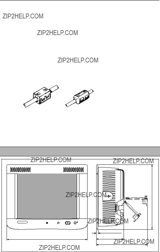
Suppression Ferrites
The following illustration shows typical cable suppression ferrites used with Raymarine equipment. Always use the ferrites supplied by Raymarine.
D3548-3
Connections to Other Equipment
If your Raymarine equipment is to be connected to other equipment using a cable not supplied by Raymarine, a suppression ferrite MUST always be attached to the cable near to the Raymarine unit.
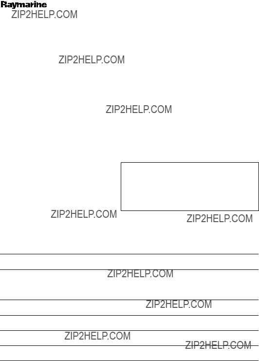
Console Mounting - Display Dimensions
Console Mounting - Preparation
3 Cut aperture in surface
302.2 mm (11.9 in)
To ensure correct dimensions, use the template provided.
Drill 4. mounting 1 (4 mm positions)diameterhole
2Using template drill mounting hole 4.1mm (0.16 in)
diameter (4 positions)
D6313-1
13
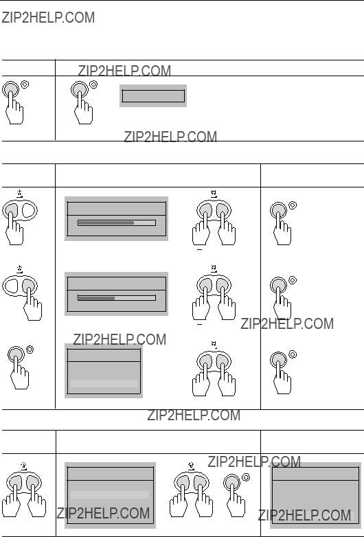
Console Mounting
4
1
3
2
5
6
7
8
-35.027??
20.024??
6 mm (0.24 in) min.
18 mm (0.71 in) max.
D6314-1
To mount the console:
1.Remove the backing paper from the installation gasket.
2.Attach the installation gasket to the back of the display plate.
3.Place display into the aperture, push 4 x M4 screws through holes.
4.Assemble 2 off, side plates onto M4 screws and secure using a plain and a spring washer, affix nuts and tighten.
5.To each side of the display loosely attach in the following order, a metal washer, bracket, plastic washer, cam, penny washer, spring washer and M8 bolt
6.Operate the cams to clamp the display into position.
7.Tighten M8 bolts.
8.Clip on the front bezel.
Connections - Typical Installations
Audio, composite video or S-video input using Optional Audio/Video Junction Box
Connections to junction box via Scart
OR
phono and/or S-video. Details provided with junction box.
D6315-1
15
Connections - Accessing the Connector Panel
Push latch to release and close cover
Rotate clockwise to secure seal and cover
5 Maintenance and Problem Solving
WARNING:
The display unit contains high voltage. Adjustments require specialized service procedures and tools only available to qualified service technicians - there are no user serviceable parts or adjustments and the operator should not attempt to service the equipment. The operator should not remove the aluminium front panel of the display.
Switch off the display unit before removing the power cord.
Routine Checks
The display is a sealed unit. Maintenance procedures are therefore limited to the following periodic checks:
???Examine the cables for signs of damage, such as chafing, cuts or nicks.
???Check that the cable connectors are firmly attached.
Cleaning the Display
CAUTION:
Take care when cleaning the display. Do not wipe the display screen with a dry cloth - this could scratch the screen coating.
Do not use acid, ammonia based or abrasive products.
1.Ensure the display is disconnected from power. Wipe the display with a clean, damp cloth.
2.If necessary, use IPA (iso-propyl alcohol) or a mild detergent solution to remove grease marks.
EMC Servicing and Safety Guidelines
???Raymarine equipment should be serviced only by authorized Raymarine service tech- nicians. They will ensure that service procedures and replacement parts used will not affect performance. There are no user serviceable parts in any Raymarine product.
???Some products generate high voltages, so never handle the cables/connectors when power is being supplied to the equipment.
???When powered up, all electrical equipment produces electromagnetic fields. These can cause adjacent pieces of electrical equipment to interact with one another, with a consequent adverse effect on operation. In order to minimise these effects and enable you to get the best possible performance from your Raymarine equipment, guidelines are given in the installation instructions, to enable you to ensure minimum interaction between different items of equipment, i.e. ensure optimum Electromagnetic Compat- ibility (EMC).
???Always report any EMC-related problem to your nearest Raymarine dealer. We use such information to improve our quality standards.
???In some installations, it may not be possible to prevent the equipment from being affected by external influences. In general this will not damage the equipment but it can lead to spurious resetting action, or momentarily may result in faulty operation.
17
Problem Solving
All Raymarine products are, prior to packing and shipping, subjected to comprehensive test and quality assurance programs. However, if this unit should develop a fault, please refer to the following table to identify the most likely cause and the corrective action required to restore normal operation.
If you still have a problem after referring to the table below, contact your local dealer, national distributor or Raymarine Technical Services Department for further advice.
Always quote the product serial numbers. The display unit serial number is printed on the back of the unit.
Common Problems and Their Solutions
The display switches off unexpect- edly
18M1500 Marine Monitor
Trunnion Mount Bracket Kit E05011
Warranty Certificate
The Raymarine warranty terms and conditions as described below do not affect the customer???s statutory rights.
Limited Warranty
Raymarine warrants each new Light Marine Product to be of good materials and workmanship. Raymarine, or it???s approved agents, will repair or exchange under warranty any parts proven to be defective in material or workmanship under normal use, for a period of 2 years/24 months from date of sale to end user, or 30 months from date of shipment from Raymarine ??? whichever expires first, except as provided below.
Raymarine Limited Warranty covers the parts and labor associated with any warranty repair as described above, provided that the unit is returned to Raymarine or one of it???s appointed agents.
Installed Warranty
In addition to the Limited Warranty cover as described above, Raymarine will, except as provided below, cover travel costs (auto mileage and tolls) up to 100 round trip highway miles (160 kilometers) and travel time of 2 hours, to enable onboard warranty service to be carried out on products where proof of installation or com- mission by Raymarine certified installers, can be shown.
The Installed Warranty provides for onboard repair or exchange, by Raymarine or it???s approved service agents, for a period of 2 years/24 months, from date of sale of the boat to the end user ??? where the equipment has been installed by a Raymarine certified installer, or from commissioning of the installation by a Raymarine certified installer, or 30 months from date of shipment of the equipment from Raymarine ??? whichever expires first, except as provided below.
Obtaining Warranty Service
In the event of Warranty service being required, contact Raymarine or the nearest Raymarine certified service agent ??? a full list of local service agents are available on the Internet or can be requested from the nearest Ray- marine agent.
A suitable proof of purchase, showing date, place of purchase, and serial number must be made available to Raymarine or authorized service agent at the time of request for Warranty service.
In cases where a Raymarine certified installer has not installed the product; i.e. Limited Warranty, the affected unit must be returned to the local Raymarine approved service agent, with a copy of proof of purchase and/or completed warranty card. Subject to the Limitations below, the unit will be repaired/replaced at no fur- ther cost to the user and promptly returned to the user.
In cases where the equipment has been installed by a Raymarine certified installer (boat builder, installer dealer etc.), i.e. Installed Warranty, the nearest local service agent should be contacted and onboard service requested, the warranty card, correctly completed and stamped by the installing agent, must be available as authorization for onboard service.
Warranty Limitations
Raymarine Warranty policy does not apply to equipment that has been subjected to accident, abuse or misuse, shipping damage, alterations, corrosion, incorrect and/or non-authorized service, or equipment on which the serial number has been altered, mutilated or removed.
Raymarine assumes no responsibility for damage incurred during installation or as a result of improper instal- lation.
This Warranty does not cover routine system checkouts, alignment/calibration, sea-trials or commissioning, unless required by replacement of part(s) in the area being aligned.
A suitable proof of purchase, showing date, place, and serial number must be made available to Raymarine or authorized service agent at the time of request for Warranty service.
Consumable items, (such as: fuses, batteries, drive belts, radar mixer diodes, snap-in impeller carriers, impel- lers, impeller bearings, and impeller shaft) are specifically excluded from this Warranty.
All costs associated with transducer replacement, other than the cost of the transducer itself, are specifically excluded from this Warranty.
Overtime/premium labor portion of services outside of normal working hours is not covered by this Warranty.
Continued. . .
Travel cost allowance on certain products with a suggested retail price below $2500.00 is not authorized. When/or if repairs are necessary, these products must be forwarded to a Raymarine facility or an authorized dealer at owner???s expense and then will be returned via surface carrier at no cost to the owner.
Travel costs other than auto mileage, tolls and two (2) hours travel time, are specifically excluded on all prod- ucts. Travel costs, which are excluded from the coverage of this Warranty, include but are not limited to: taxi, launch fees, aircraft rental, subsistence, customs, shipping and communication charges etc. Travel costs, mile- age and time, in excess to that allowed must have prior approval in writing.
TO THE EXTENT CONSISTENT WITH STATE AND FEDERAL LAW:
(1)THIS WARRANTY IS STRICTLY LIMITED TO THE TERMS INDICATED HEREIN, AND NO
OTHER WARRANTIES OR REMEDIES SHALL BE BINDING ON RAYMARINE INCLUDING WITH-
OUT LIMITATION ANY WARRANTIES OF MERCHANTABLE OR FITNESS FOR A PARTICULAR
PURPOSE.
(2)Raymarine shall not be liable for any incidental, consequential or special (including punitive or multiple) damages.
All Raymarine products sold or provided hereunder are merely aids to navigation. It is the responsibility of the user to exercise discretion and proper navigational skill inde- pendent of any Raymarine equipment.
Document number: 84066-9 July 2002
Factory Service Centers
Stick barcode label here
Dealer address
Commissioned by
Commissioning date
Owner???s name
Mailing address
This portion should be completed and retained by the owner.