Patent Pending

Model No. PFEX20020

Serial No.

Serial

Number

Decal

QUESTIONS?

If you have questions, or if there are missing or damaged parts, we will guarantee complete sat- isfaction through direct assis- tance from our factory.

TO AVOID DELAYS, PLEASE

CALL DIRECT TO OUR TOLL- FREE CUSTOMER HOT LINE. The trained technicians on our cus- tomer hot line will provide imme- diate assistance, free of charge to you.

CUSTOMER HOT LINE:

1-800-999-3756

Mon.-Fri., 6 a.m.-6 p.m. MST

CAUTION

Read all precautions and instruc- tions in this manual before using this equipment. Keep this manual for future reference.

USER'S MANUAL

__-Visit our website at

www.proform.com

new products, prizes,

fitness tips, and much more!

IMPORTANT PRECAUTIONS

"_A.=WARNING: To reduce the risk of serious injury, read the following important precau- tions before using the exercise cycle.

1.Read all instructions in this manual before using the exercise cycle.

2.It is the responsibility of the owner to ensure that all users of the exercise cycle are ade- quately informed of all precautions. Use the exercise cycle only as described in this manual.

3.Use the exercise cycle indoors on a level sur-

face. Keep the exercise cycle away from moisture and dust. Place a mat under the

exercise cycle to protect the floor.

4.Inspect and properly tighten all parts regular- ly. Replace any worn parts immediately.

5.Keep children under the age of 12 and pets away from the exercise cycle at all times.

6.Wear appropriate clothes when exercising; do not wear loose clothes that could become caught on the exercise cycle. Always wear athletic shoes for foot protection,

7.The exercise cycle should not be used by persons weighing more than 250 pounds.

8.Always keep your back straight when using the exercise cycle; do not arch your back.

9.If you feel pain or dizziness while exercising, stop immediately and cool down.

10.The exercise cycle does not have a free wheel; the pedals will continue to move until the fly- wheel stops.

11.The pulse sensor is not a medical device. Various factors, including the user's move- ment, may affect the accuracy of heart rate readings. The pulse sensor is intended only as an exercise aid in determining heart rate trends in general.

12.The exercise cycle is intended for home use only. Do not use the exercise cycle in

a commercial, rental, or institutional setting.

_ WARNING: Before beginning this or any exercise program, consult your physician. This

is especially important for persons over the age of 35 or persons with pre-existing health problems. Read all instructions before using. ICON assumes no responsibility for personal injury or property damage sustained by or through the use of this product.

2

BEFORE YOU BEGIN

Congratulations for selecting the new PROFORM ?? SR 20 exercise cycle. Cycling is one of the most effective exercises for increasing cardiovascular fitness, building endurance, and toning the entire body. The PRO- FORM _ SR 20 offers a selection of features designed to let you enjoy this healthful exercise in the conve- nience and privacy of your home.

For your benefit, read this manual carefully before

you use the exercise cycle. If you have questions after reading this manual, please call our Customer

Handlebar

Console

Pulse Sensor

Seat

REAR

Service Department toll-free at 1-800-999-3756, Monday through Friday, 6 a.m. until 6 p.m. Mountain Time (excluding holidays). To help us assist you, please note the product model number and serial number before calling. The model number is PFEX20020. The serial number can be found on a decal attached to the exercise cycle (see the front cover of this manual).

Before reading further, please familiarize yourself with the parts that are labeled in the drawing below.

Water Bottle Holder*

Resistance Knob

FRONT

Seat Knob

Pedal/Strap

RIGHT SIDE

*No water bottle is included

3

ASSEMBLY

Assembly requires two persons. Place all parts of the exercise cycle in a cleared area and remove the packing materials. Do not dispose of the packing materials until assembly is completed.

Use the part drawings below to identify the small parts used in assembly. The number in parenthesis below each drawing refers to the key number of the part, from the PART LIST on page 14. The second number refers to the quantity needed for assembly. Note: Some small parts may have been pre-attached for shipping. If a part is not in the parts bag, check to see if it has been pre-attached.

,Identify the Front Stabilizer (2). While another person lifts the front of the Frame (1) slightly, attach the Front Stabilizer to the Frame with two M10 x 75mm Carriage

4

,While another person lifts the back of the Frame (1) slightly, attach the Rear Stabilizer (30) to the Frame with two M10 x 75mm Carriage Bolts (33) and two M10 Black Nylon Locknuts (34).

3.Attach the Handlebar (15) to the Upright (13) with two M10 x 42mm Button Bolts (6), two M10 Split Washers (46), and two M10 Black Nylon Locknuts (34).

4.The Console (16) requires three "AA" batteries (not

included); alkaline batteries are recommended. Insert three batteries into the Console as shown. Make sure

that the batteries are oriented as shown by the dia- gram inside the Console.

,Hold the Console (16) near the Upright (13). Insert the console cable and the console wire into the indicated hole and down through the Upright. Attach the ground wire to the Upright with an M4 x 16mm Screw (32).

Insert the excess wire and cable into the Upright (13). Attach the Console (16) to the Upright with four M4 x 16mm Screws (32). Make sure that the wires and the cable are not pinched.

2

34

30

3

34

6

13

4

Batteries

Ground

Wire

32

Console

Console Wire

Cable

5

6.While another person holds the Upright (13) in the position shown, connect the console wire to the Reed Switch Wire (43). Next, connect the console cable to the Lower Cable (36) in the following way:

???Refer to inset drawing A. Pull up on the metal brack- et on the Lower Cable (36), and insert the tip of the

console cable (CC) into the wire clip inside of the metal bracket.

???Refer to inset drawing B. Firmly pull the console cable (CC) and slide it into the metal bracket on the Lower Cable (36) as shown.

???Refer to inset drawing C. Using pliers, squeeze the prongs on the upper end of the metal bracket together.

Insert the excess wire and cable down into the Frame

(1). Insert the Upright (13) into the Frame. Make sure that the wires and cables are not pinched. Attach the Upright to the Frame with three M8 x 25mm Button Screws (47) and three M8 Black Split Washers (42).

7.Attach the Seat (12) to the Seat Post (5) with four M8 Nylon Locknuts (10) and four M8 Black Split Washers (42). Note: The Nylon Locknuts and Split Washers may be preattached to the Seat.

Turn the Seat Knob (28) counterclockwise two or three turns to loosen it (if the Seat Knob is not loosened enough, it may scratch the Seat Post [5]). Next, pull the Seat Knob, slide the Seat Post into the Frame (1), and then release the Seat Knob. Move the Seat Post up and down slightly until the pin on the Seat Knob snaps into one of the holes in the Seat Post. Then, turn the Seat Knob clockwise until it is tight.

47nsole

C_n_r1

ABC

BMet_let _(I

Metal j

CC i Bracket

......

12/

1

6

(40). Tighten the Right Pedal (not shown) clockwise

40

into the Right Crank Arm. Important: Tighten both

Pedals as firmly as possible. After using the exercise cycle for one week, retighten the Pedals. For best performance, the Pedals must be kept tightened.

Adjust the left Pedal Strap (25) to the desired posi- tion, and press the end of the Pedal Strap onto the tab on the side of the Left Pedal (24). Adjust the other Pedal Strap (not shown) in the same way.

9.Make sure that all parts are properly tightened before you use the exercise cycle. Note: After assembly is

completed, some extra parts may be left over. Place a mat beneath the exercise cycle to protect the floor.

7

HOW TO OPERATE THE EXERCISE CYCLE

HOW TO ADJUST THE SEAT

loosen it (if the knob is not loosened enough, it may scratch the seat post). Next, pull the knob, slide the seat post to the desired height, and then release the knob. Move the seat post up and down slightly until the pin on the knob snaps into one of the holes in the seat post. Then, turn the knob clockwise until it is tight.

HOW TO ADJUST THE PEDALING RESISTANCE

To adjust the pedal-

ing resistance, turn the resistance knob

on the console.

Important: Stop turning the knob

when turning becomes difficult, or the console may become damaged.

HOW TO ADJUST THE PEDAL STRAPS

and then press the ends of the pedal

straps back onto the tabs.

8

89:S

The easy-to-use console features seven modes that provide instant exercise feedback during your work- outs. The modes are described below.

Speed--This mode displays your pedaling speed.

Time--This mode displays the elapsed time. Note: When you stop pedaling for a few seconds, the time mode will pause.

Distance--This mode displays the distance you have pedaled.

Calories--This mode displays the approximate num- ber of calories you have burned.

Fat Calories--This mode displays the approximate number of fat calories you have burned (see FAT BURNING on page 12).

Scan--This mode displays the speed, time, distance, calorie, and fat calorie modes, for a few seconds each, in a repeating cycle.

Pulse (BPM)--This mode displays your heart rate when you use the pulse sensor.

Note: The console can display speed and distance in either miles or kilometers. To change the unit of measurement, hold down the On/Reset button for a few seconds. The mode indicators will show which unit of measurement is selected. When the batter- ies are replaced, it may be necessary to reselect the desired unit of measurement.

Make sure that there are batteries in the console (see BATTERY REPLACEMENT on page 11). If there is a thin sheet of clear plastic on the console, remove it.

Follow the steps below to operate the console.

,To turn on the power, press the On/Reset button or simply begin pedaling. When the power is turned on, the entire display will appear for two seconds. The console will then be ready for use.

the scan mode is selected, and a second mode

indicator will show which mode is currently dis- played. Note: If a different mode is selected, you can select the scan mode again by repeatedly pressing the Display Mode button.

until only the MPH (or Km/H), Time, Miles (or Kms), Cals., or Fat Cals. indicator appears in the display. Make sure that the Scan indicator does not appear.

To reset the display, press the On/Reset button.

9

3. Measure your heart rate if desired.

To use the pulse sensor, hold the handle on the console, with your right palm covering the two right contacts and your left palm covering the two left contacts. Avoid moving your hands. When your pulse is detected, the heart-shaped indica- tor in the display will flash each time your heart beats and two dashes (--) will appear. After a moment, your heart rate will be shown. For the most accurate heart rate reading, continue to hold the handgrips for about 15 seconds.

WARNING: The heart rate sensor is not a medical device. Various factors may affect the accuracy of heart rate readings. The heart rate sensor is intended only as an exercise aid in deter- mmmg heart rate trends in general.

4.To turn off the power, simply wait for a few minutes. The console has an "auto-off" feature. If the pedals are not moved and the console buttons are not pressed for a few minutes, the power will automatically turn off to conserve the bat- teries.

10

MAINTENANCE AND TROUBLESHOOTING

Inspect and properly tighten all parts of the exercise cycle regularly. Replace any worn parts immediately.

To clean the exercise cycle, use a damp cloth and a small amount of mild soap. Important: To avoid damage to the console, keep liquids away from the console and keep the console out of direct

sunlight.

PULSE SENSOR TROUBLESHOOTING

For optimal performance of the pulse sensor, keep the metal contacts clean. The contacts can be cleaned with a soft cloth--never use alcohol, abrasives, or chemicals.

Avoid moving your hands while using the pulse sen- sor. Excessive movement may interfere with heart rate readings. Do not hold the metal contacts too tightly; doing so may interfere with heart rate read- ings. For the most accurate heart rate reading, hold the metal contacts for about 15 seconds.

HOW TO ADJUST THE REED SWITCH

If the console does not display correct feedback, the reed switch should be adjusted. To adjust the reed switch, the left side shield must be removed.

First, remove the seven M4 x 25mm Screws (41) from the Right Side Shield (18). Next, remove the M4 x 12mm Round Head Screw (29) from the right side of the Side Shield Cover (19).

19

Using an adjustable wrench, turn the Left Pedal (24) clockwise and remove it. Next, remove the two M4 x 16mm Screws (32) from the Left Side Shield (17) and the M4 x 12mm Round Head Screw (29) from the

Side Shield Cover (19). Lift off the Side Shield Cover and the Left Side Shield.

24

indicated M4 x 16mm Screw (32). Slide the Reed Switch slightly closer to or away from the Magnet. Retighten the Screw. Turn the Crank Arm for a moment. Repeat until the console displays correct feedback. When the Reed Switch is correctly adjust- ed, reattach the left side shield, the side shield cover, and the left pedal.

BATTERY REPLACEMENT

If the console display becomes dim, the batteries should be replaced; most console problems are the result of low batteries. To replace the batteries, refer to assembly step 5 on page 5 and remove the con- sole from the upright. Next, refer to step 4 and insert three batteries into the console. Reattach the console to the upright. Be careful not to pinch the wires or the cable.

11

CONDITIONING GUIDELINES

The following guidelines will help you to plan your exercise program. Remember that proper nutrition and adequate rest are essential for successful results.

WARNING:

Before beginning this or any exercise pro- gram, consult your physician. This is espe- cially important for persons over the age of 35 or persons with pre-existing health problems.

??The pulse sensor is not a medical device. Various factors may affect the accuracy of heart rate readings. The pulse sensor is intended only as an exercise aid in deter- mining heart rate trends in general.

EXERCISE INTENSITY

Whether your goal is to burn fat or to strengthen your cardiovascular system, the key to achieving the desired results is to exercise with the proper intensity. The proper intensity level can be found by using your heart rate as a guide. The chart below shows recom- mended heart rates for fat burning, maximum fat burning, and cardiovascular (aerobic) exercise.

165 155 145 140 130 125 115 (_

145 138 130 125 118 110 103 C,_?

125 120 115 110 105 95 90

20 30 40 50 60 70 80

To find the proper heart rate for you, first find your age at the bottom of the chart (ages are rounded off to the nearest ten years). Next, find the three numbers above your age. The three numbers are your "training zone." The lowest number is the recommended heart rate for fat burning; the middle number is the recommended heart rate for maximum fat burning; the highest num- ber is the recommended heart rate for aerobic exer- cise.

Fat Burning

To burn fat effectively, you must exercise at a relative- ly low intensity level for a sustained period of time.

During the first few minutes of exercise, your body uses easily accessible carbohydrate calories for ener- gy. Only after the first few minutes of exercise does your body begin to use stored fat calories for energy. If your goal is to burn fat, adjust the intensity of your exercise until your heart rate is near the lowest num- ber in your training zone as you exercise. For maxi- mum fat burning, adjust the intensity of your exercise until your heart rate is near the middle number in your training zone as you exercise.

Aerobic Exercise

If your goal is to strengthen your cardiovascular sys- tem, your exercise must be "aerobic." Aerobic exer- cise is activity that requires large amounts of oxygen for prolonged periods of time. This increases the demand on the heart to pump blood to the muscles, and on the lungs to oxygenate the blood. For aerobic exercise, adjust the intensity of your exercise until your heart rate is near the highest number in your training zone.

WORKOUT GUIDELINES

Each workout should include the following three parts:

A warm-up, consisting of 5 to 10 minutes of stretching and light exercise. A proper warm-up increases your body temperature, heart rate, and circulation in prepa- ration for exercise.

Training zone exercise, consisting of 20 to 30 min- utes of exercising with your heart rate in your training zone. Note: During the first few weeks of your exer- cise program, do not keep your heart rate in your training zone for longer than 20 minutes.

A cool-down, with 5 to 10 minutes of stretching. This will increase the flexibility of your muscles and will help to prevent post-exercise problems.

EXERCISE FREQUENCY

To maintain or improve your condition, plan three work- outs each week, with at least one day of rest between workouts. After a few months of regular exercise, you may complete up to five workouts each week, if desired. Remember, the key to success is make exer- cise a regular and enjoyable part of your everyday life.

12

SUGGESTED STRETCHES

The correct form for several basic stretches is shown at the right. Move slowly as you stretch--never bounce.

1. Toe Touch Stretch

Stand with your knees bent slightly and slowly bend forward from your hips. Allow your back and shoulders to relax as you reach down toward your toes as far as possible. Hold for 15

counts, then relax. Repeat 3 times. Stretches: Hamstrings, back of knees and back.

2. Hamstring Stretch

Sit with one leg extended. Bring the sole of the opposite foot toward you and rest it against the inner thigh of your extended leg. Reach toward your toes as far as possible. Hold for 15 counts, then relax. Repeat 3 times for each leg. Stretches: Hamstrings, lower back and groin.

3. Calf/Achilles Stretch

With one leg in front of the other, reach forward and place your hands against a wall. Keep your back leg straight and your back foot flat on the floor. Bend your front leg, lean forward and move your hips toward the wall. Hold for 15 counts, then relax. Repeat 3 times for each leg. To cause further stretching of the achilles

tendons, bend your back leg as well. Stretches: Calves, achilles tendons and ankles.

4. Quadriceps Stretch

With one hand against a wall for balance, reach back and grasp one foot with your other hand. Bring your heel as close to your buttocks as possible. Hold for 15 counts, then relax. Repeat 3 times for each leg. Stretches: Quadriceps and hip muscles.

5. Inner Thigh Stretch

Sit with the soles of your feet together and your knees outward. Pull your feet toward your groin area as far as possible. Hold for 15 counts, then relax. Repeat 3 times. Stretches: Quadriceps and hip muscles.

13

Note: "#" indicates a non-illustrated part. Specifications are subject to change without notice. See the back cover of this manual for information about ordering replacement parts.

14

EXPLODED DRAWING--Model No. PFEX20020

4141

29

31

33

31

39

27

1

34 21--_"

34

37

17

Ro8o2A

41

1

32

15

HOW TO ORDER REPLACEMENT PARTS

To order replacement parts, call our Customer Service Department toll-free at 1-800-999-3756, Monday through Friday, 6 a.m. until 6 p.m. Mountain Time (excluding holidays). To help us assist you, please be prepared to give the following information:

???The MODEL NUMBER of the product (PFEX20020)

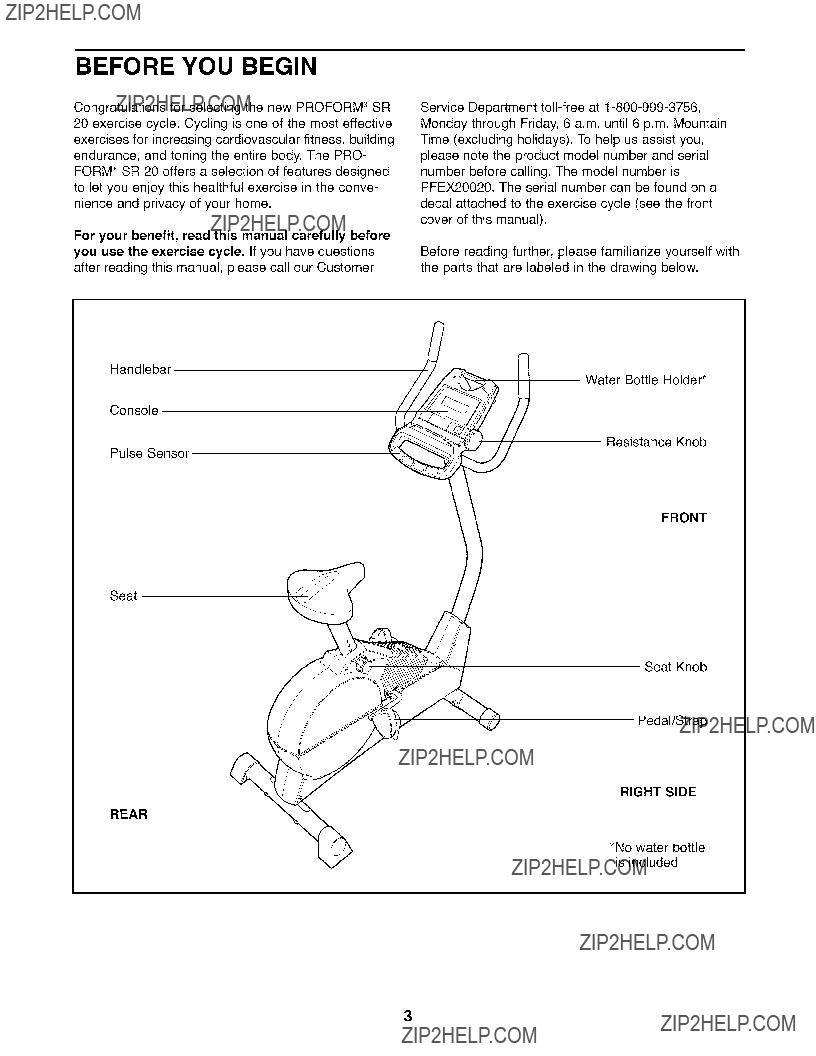
???The NAME of the product (PROFORM _ SR 20 exercise cycle)

???The SERIAL NUMBER of the product (see the front cover of this manual)

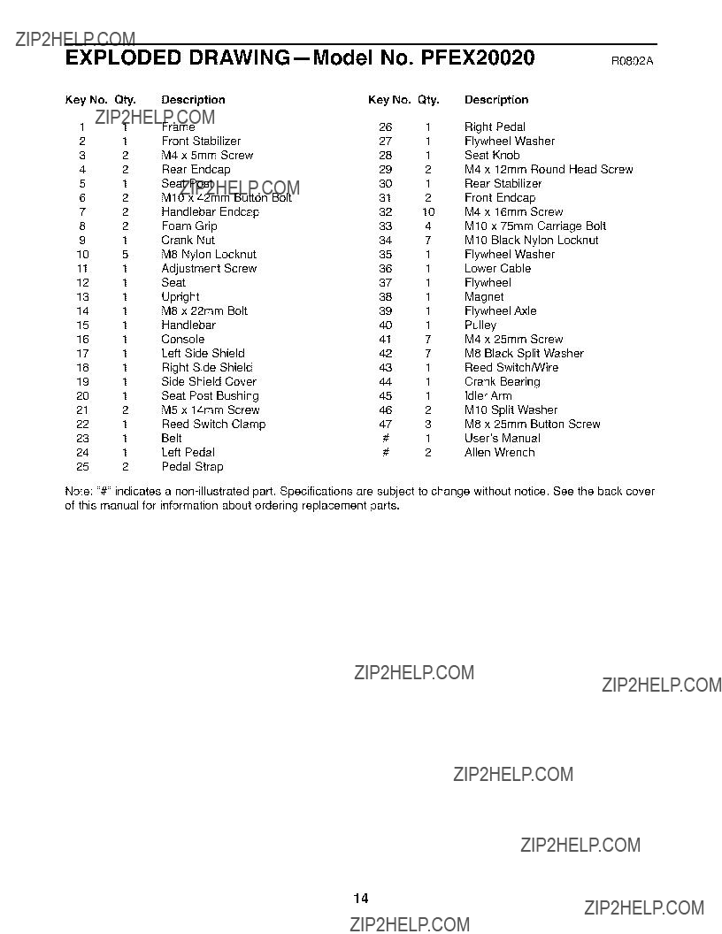
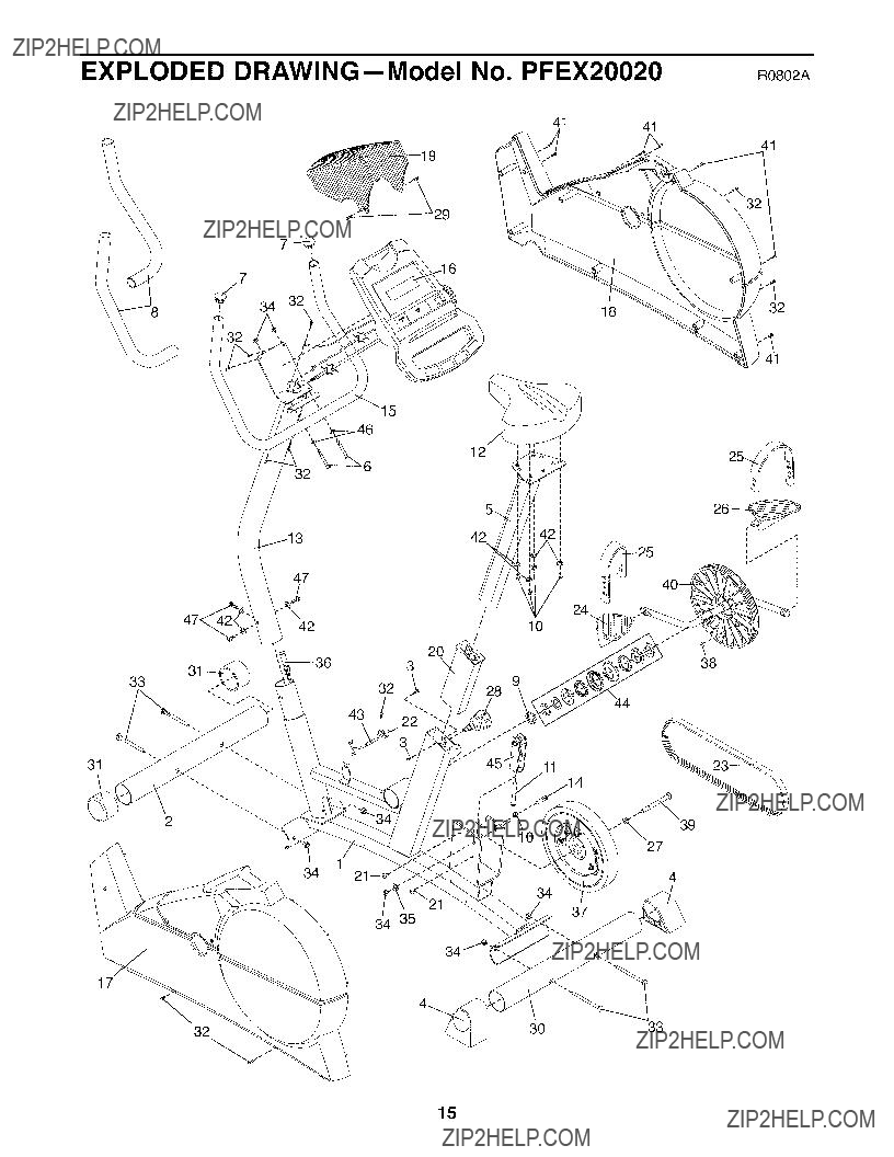
???The KEY NUMBER and DESCRIPTION of the part(s) (see the PART LIST on page 14 and the EXPLODED DRAWING on page 15)

PROFORM is a registered trademark of ICON Health & Fitness, Inc.

LIMITED WARRANTY

ICON Health & Fitness, Inc. (ICON), warrants this product to be free from defects in workmanship and material, under normal use and service conditions, for a period of ninety (90) days from the date of pur- chase. This warranty extends only to the original purchaser. ICON'sobligation under this warranty is lim- ited to replacing or repairing, at ICON's option, the product through one of its authorized service centers. All repairs for which warranty claims are made must be pre-authorized by ICON. This warranty does not extend to any product or damage to a product caused by or attributable to freight damage, abuse, mis- use, improper or abnormal usage or repairs not provided by an ICON authorized service center, products used for commercial or rental purposes, or products used as store display models. No other warranty beyond that specifically set forth above is authorized by ICON.

ICON is not responsible or liable for indirect, special or consequential damages arising out of or in con- nection with the use or performance of the product or damages with respect to any economic loss, loss of property, loss of revenues or profits, loss of enjoyment or use, costs of removal, installation or other consequential damages of whatsoever nature. Some states do not allow the exclusion or limitation of inci- dental or consequential damages. Accordingly, the above limitation may not apply to you.

The warranty extended hereunder is in lieu of any and all other warranties and any implied warranties of merchantability or fitness for a particular purpose is limited in its scope and duration to the terms set forth herein. Some states do not allow limitations on how long an implied warranty lasts. Accordingly, the above limitation may not apply to you.

This warranty gives you specific legal rights. You may also have other rights which vary from state to state.

ICON HEALTH & FITNESS, INC., 1500 S. 1000 W., LOGAN, UT 84321-9813