MODEL #DB6701
16 IN. REEL MOWER
Espa??ol p. XX12
Questions, problems, missing parts? Before returning to your retailer, call our customer service department at
1
MODEL #DB6701
16 IN. REEL MOWER
Espa??ol p. XX12
Questions, problems, missing parts? Before returning to your retailer, call our customer service department at
1

PRODUCT SPECIFICATIONS
2

 SAFETY INFORMATION
Please read and understand this entire manual before attempting to assemble, operate or install the product. If you have any questions regarding the product, please call customer service at
Never place hands, fingers or feet inside the reel. Although a motor does not power this mower, when the wheels turn the reel spins and can cut.
Never mow when grass is wet as it can be slippery.
Do not use the reel mower while barefoot or while wearing sandals.
Walk behind, never run, while using reel mower. Always make sure of your footing when using this reel mower. Never intentionally strike or hit trees, fences, etc. This can cause injuries or severely damage the reel mower mechanisms.
Make sure your reel mower is in a safe operating condition. Do not attempt to operate this reel mower if dam- aged. Contact customer service or have the reel mower repaired by a qualified repair service provider before using.
CAUTION
READ YOUR OPERATOR???S MANUAL COMPLETELY AND CAREFULLY BEFORE ATTEMPTING TO SET
UP OR OPERATE YOUR NEW REEL MOWER. ALL OPERATORS OF THIS EQUIPMENT SHOULD READ
AND UNDERSTAND ALL SAFETY RULES PRINTED ON THE MACHINE AND IN THIS OPERATOR???S
MANUAL BEFORE USE.
3

PACKAGE CONTENTS
A
B
C
D
E
4

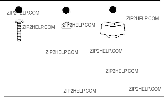
HARDWARE CONTENTS
PREPARATION
Before beginning assembly of product, make sure all parts are present. Compare parts with package contents list and hardware contents list. If any part is missing or damaged, do not attempt to assemble the product.
Estimated Assembly Time: Less than 15 minutes.
5

ASSEMBLY INSTRUCTIONS
ASSEMBLING THE HANDLE
1
A
1.Insert the two center handle pieces (C) into the left and right side of the top handle (B) and secure with two
carriage bolts (AA), washers (BB), and fixing knobs (CC).
NOTE: The carriage bolts should be inserted from the downside of the handle so that the washers and the fixing knobs are inserted upside of the handle.
2.Attach the top handle subassembly to the lower handle
(D) using four carriage bolts (AA), washers (BB), and fixing knobs (CC).
NOTE: The carriage bolts should be inserted from the inside of the handle so that the washers and the fixing knobs are inserted outside of the handle.
B  BB
BB
C 
 CC
CC
2
CC
AA
6
ASSEMBLY INSTRUCTIONS
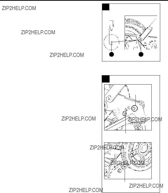
ATTACHING THE HANDLE TO THE MOWER BASE
3.Align the holes at the bottom of the arms of the lower handle (D) with the posts extending from the side plates on the reel mower body (E). Slide lower ends of handle arms onto posts.
3
DE
CUTTING HEIGHT ADJUSTMENTS
1.The cutting height of the mower can be adjusted from 5/6 ???
adjustment height, using the roller assembly.
2.For the highest cutting level, move the adjustment knobs to position A as shown in Fig. 4.
3.For the lowest cutting level, move the adjustment knobs to position B as shown in Fig. 4.
4.Other cutting heights are achieved by moving the adjustment knobs to any stop between the highest and lowest positions.
NOTE: The maximum grass cutting height for most grass types is 3 in. If the grass exceeds 3 in., the following guidelines are recommended; however, results will vary depending on lawn type and condition.
 Increase cutting height for initial cutting, then lower as needed during repeat cutting.
 Overlap cutting paths.
 Mow the same path in opposite directions.
4
The highest cutting position
position A


 position B
The lowest cutting position
The height adjustment knob
7

OPERATING INSTRUCTIONS
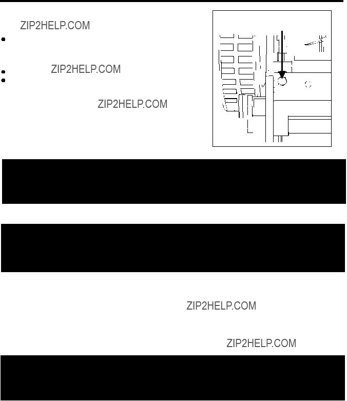
MOWER BLADE ADJUSTMENT
NOTE: Blades are factory adjusted.
Misalignment can occur, often caused by blades being too loose or too tight. This can cause an uneven cut or difficulty pushing the mower.
Each end of the cutting bar is adjusted separately. To move the cutting bar closer to the blades, turn the adjustment screw clockwise. To move the cutting bar away from the blades, turn the adjustment screw counterclockwise.
 WARNING
Adjustment screw
BLADES ARE EXTREMELY SHARP. TO AVOID INJURY, DO NOT TOUCH BLADES WHEN
MAKING ADJUSTMENTS.
CAUTION
 djusting the screws for blade adjustments is a very sensitive procedure. A sixteenth of a turn is considered a major adjustment.
  efore tightening one adjustment screw, make sure to loosen the opposite screw an equal amount.
1.Turn mower upside down.
2.Insert a piece of paper between cutter bar and reel blades and slowly turn wheel by hand.
3.All blades should slice the paper evenly along the entire length of the cutter bar while the reel turns smoothly.
4.If mower has an intermittent cut, adjustment should be made to the appropriate side of blades to attain proper cutting action.
 WARNING
Do not overtighten adjustment screws, as this could damage cutter bar. Both screws must be tight on final adjustment.
8

CARE AND MAINTENANCE
1.Minimum care is required to ensure smooth operation of your mower.
2.To avoid damage to mower or cutting blades, keep area to be mowed free from debris.
3.For best results, regularly apply lubricant to mower s cutting surfaces, cutting reel axle shaft and wheels.
??Reel mowers are not effective for rough terrain, excessively bumpy or overgrown yards. If the wheels do not have traction and cannot turn at a steady fast rotation, the blade will not turn fast enough to cut the grass. In addition, the reel mower can only cut the blades of grass that are between the reel and the cutter bar. Uneven terrain makes it increasingly difficult for cutting.
??Reel mowers may not typically cut wood stems, branches, or tall thick grass types such as Zoysia, St Augustine and Bermuda. In addition, they have difficulty cutting tall weeds such as dandelions and buckthorn. The reel mower may tend to push them over and not actually cut them.
??Reel mowers do not cut close to the edge of the mower. The wheels of a reel mower are outside of the blades.
 WARNING
Sharpening the cutting blades:
1.Spread a thin layer of lapping compound on the front edge of the reel blades.
2.Adjust the cutter bar so that the blade has light but firm contact across the full width of the cutter bar.
CAUTION
3. Turn the reel blades until the front edge of the cutter bar blade is polished.
NOTE: Clean any grinding compound or debris from the cutter bar blade, reel blade, pinions, and pawls.
NOTE: Use industrial or valve lapping compound between 100 and 240 grit. Lubricate the axle and pinion with a light film of wheel bearing grease.
Cleaning and Storage:
1.Clean the exterior of the machine thoroughly using a soft brush and cloth before storing. Do not use water, solvents or polishes.
2.Turn the mower on its side to clean the blade area.
 WARNING
3. Store the mower in a dry place. Do not place other objects on top of the mower during storage.
9

WARRANTY
The manufacturer warrants to the original purchaser that each new product and service part is free from defects in material and workmanship and agrees to repair or replace under this warranty any defective product or part as follows from the original date of purchase.
 1 Year Limited Warranty
 THIS WARRANTY IS NOT TRANSFERABLE AND DOES NOT COVER:
Products sold damaged or incomplete, sold "as is," sold reconditioned or used as rental equipment.  Delivery, installation or normal adjustments explained in
 Damage or liability caused by shipping, improper handling, improper installation, incorrect voltage or improper wiring, improper maintenance, improper modification, or the use of accessories and /or attachments not specifically recommended.
 Repairs necessary because of operator abuse or negligence, or the failure to install, operate, maintain and store manual.
 Damage caused by cold, heat, rain, excessive humidity, corrosive environments and materials, or other contaminants.
 Expendable items that become worn during normal use.
 Cosmetic defects that do not interfere with tool functionality.
 Freight costs from customer to vendor.
 ANY INCIDENTAL, INDIRECT OR CONSEQUENTIAL LOSS, DAMAGE, OR EXPENSE THAT MAY RESULT
FROM ANY DEFECT, FAILURE OR MALFUNCTION OF THE PRODUCT.
 Some states do not allow the exclusion or limitations on how long an implied warranty lasts, so the above limitations may not apply to you.
 WARRANTY REPLACEMENT PARTS are available by calling the
10
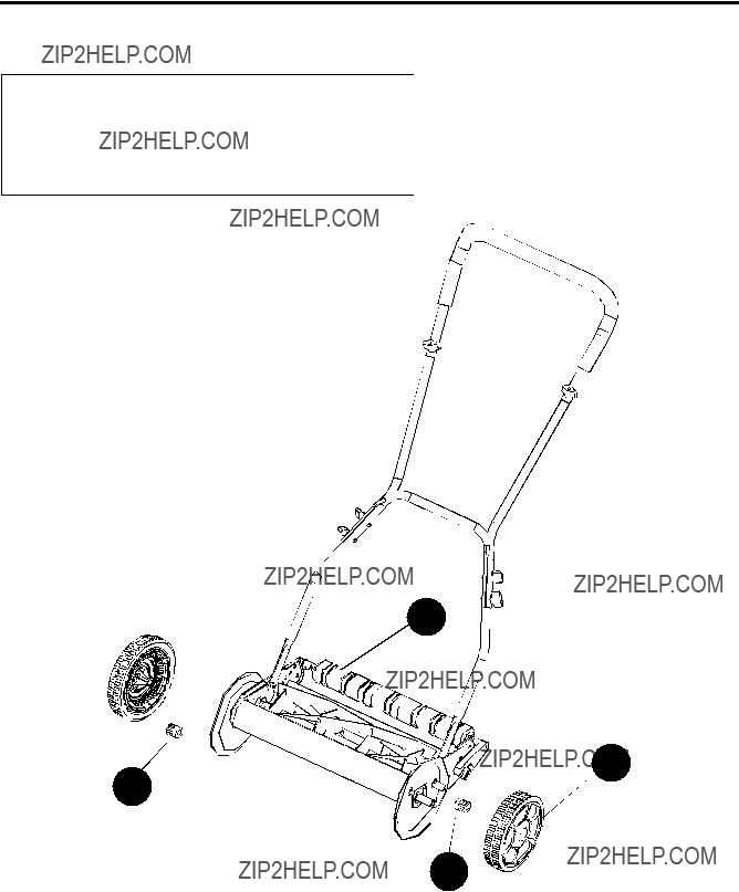
REPLACEMENT PARTS LIST
For replacement parts, call our customer service department at
I
F
H
G
11
MODELO #DB6701
PODADORA DE CARRETE DE 40 CM
ADJUNTE SU RECIBO AQU??
??Preguntas, problemas, piezas faltantes? Antes de volver a la tienda, llame a nuestro Departamento de Servicio al Cliente al
12

ESPECIFICACIONES DEL PRODUCTO
13

 INFORMACI??N DE SEGURIDAD
Lea y comprenda completamente este manual antes de intentar ensamblar, usar o instalar el producto. Si tiene preguntas relacionadas con el producto, llame al Departamento de Servicio al Cliente al
Nunca ponga las manos, los dedos o los pies dentro del carrete. Aunque esta podadora no funciona con un motor, cuando las ruedas giran, el carrete gira y puede cortar.
Nunca pode cuando el c??sped est?? h??medo, ya que puede ser resbaladizo. No use la podadora de carrete estando descalzo o al usar sandalias.
Camine detr??s, nunca corra, al utilizar la podadora de carrete. Siempre pise firmemente al usar esta podadora de carrete.
Nunca se tope ni golpee a prop??sito ??rboles, cercas, etc. Esto puede causar lesiones o da??ar gravemente los mecanismos de la podadora de carrete.
Aseg??rese de que la podadora de carrete est?? en condiciones de funcionamiento seguras. No intente usar esta podadora de carrete si est?? da??ada. P??ngase en contacto con el Departamento de Servicio al Cliente o haga que un proveedor de servicios de reparaci??n repare la podadora de carrete antes de usarla.
PRECAUCI??N
LEA EL MANUAL DEL OPERADOR CON ATENCI??N Y EN SU TOTALIDAD ANTES DE INTENTAR
INSTALAR O USAR LA NUEVA PODADORA DE CARRETE. TODOS LOS OPERADORES DE ESTE
EQUIPO DEBEN LEER Y COMPRENDER TODAS LAS NORMAS DE SEGURIDAD IMPRESAS EN LA
M??QUINA Y EN ESTE MANUAL DEL OPERADOR ANTES DE USAR EL PRODUCTO.
14

CONTENIDO DEL PAQUETE
A
B
C
D
E
15
ADITAMENTOS
Arandela de
PREPARACI??N
Antes de comenzar a ensamblar el producto, aseg??rese de tener todas las piezas. Compare las piezas con la lista del contenido del paquete y la lista de aditamentos. No intente ensamblar el producto si falta alguna pieza o si estas est??n da??adas.
Tiempo estimado de ensamblaje: Menos de 15 minutos.
16

INSTRUCCIONES DE ENSAMBLAJE
ENSAMBLE DE LA MANIJA
1
A
1.Inserte las dos piezas de la manija central (C) en el lado izquierdo y derecho de la manija superior (B) y asegure con dos pernos cabeza de hongo (AA), arandelas (BB) y perillas de fijaci??n (CC).
NOTA: Los pernos cabeza de hongo se deben insertar desde la parte inferior de la manija, de modo que las arandelas y las perillas de fijaci??n se inserten en la parte superior de la manija.
2.Fije el subensamble de la manija superior a la manija inferior (D) con cuatro pernos cabeza de hongo (AA), arandelas (BB) y perillas de fijaci??n (CC).
NOTA: Los pernos cabeza de hongo se deben insertar desde el interior de la manija, de modo que las arandelas y las perillas de fijaci??n se inserten por fuera de la manija.
B  BB
BB
C 
 CC
CC
2
CC
AA
17

INSTRUCCIONES DE ENSAMBLAJE
FIJACI??N DE LA MANIJA A LA BASE DE LA PODADORA 3
3. Alinee los orificios en la parte inferior de los brazos
de la manija inferior (D) con los postes que se extienden desde las placas laterales en el cuerpo de la podadora de carrete (E). Deslice los extremos inferiores de los brazos de la manija hacia los postes.
DE
AJUSTES DE LA ALTURA DE CORTE
1.La altura de corte de la podadora puede regularse de 2,12 cm a 4,57 cm, con 4 posiciones para la altura de ajuste al usar el ensamble de rodillo.
2.Para el nivel de corte m??s alto, mueva las perillas de ajuste a la posici??n A, como se muestra en la fig. 4.
3.Para el nivel de corte m??s bajo, mueva las perillas de ajuste a la posici??n B, como se muestra en la fig. 4.
4.Se logran otras alturas de corte moviendo las perillas de ajuste a cualquier detenci??n entre la posici??n m??s alta y la m??s baja.
NOTA: La altura m??xima de corte de c??sped para la mayor??a de tipos de c??sped es de 7,62 cm. Si el c??sped mide m??s de 7,62 cm, se recomiendan las siguientes pautas; sin embargo, los resultados depender??n del tipo de c??sped y del estado del mismo.
 Aumente la altura de corte para el corte inicial, luego disminuya seg??n sea necesario durante cortes repetidos.
 Superponga l??neas de corte.
 Pode la misma l??nea en direcciones opuestas.
4
La posici??n de corte m??s alta
posici??n A


 posici??n B
La posici??n de corte m??s baja
La perilla de ajuste de altura
18
INSTRUCCIONES DE FUNCIONAMIENTO
AJUSTE DE LA CUCHILLA DE LA PODADORA
NOTA: Las cuchillas vienen ajustadas de f??brica.
Es posible que se desalineen, con frecuencia debido
a cuchillas demasiado sueltas o apretadas. Esto puede provocar un corte disparejo o dificultad al empujar la podadora.
Cada extremo de la barra de corte se ajusta por separado.
Para mover la barra de corte m??s cerca de
las cuchillas, gire el tornillo de ajuste en direcci??n de las manecillas del reloj. Para mover la barra de corte lejos de las cuchillas, gire el tornillo de ajuste en direcci??n contraria a las manecillas del reloj.
ADVERTENCIA
Tornillo de ajuste
LAS CUCHILLAS EST??N EXTREMADAMENTE AFILADAS. PARA EVITAR LESIONES,
NO TOQUE LAS CUCHILLAS AL REALIZAR AJUSTES.
PRECAUCI??N
El ajuste de los tornillos para ajustar la cuchilla es un procedimiento muy delicado. Un dieciseisavo de giro se considera un ajuste importante. Antes de apretar un tornillo de ajuste, aseg??rese de soltar el tornillo opuesto en igual cantidad.
1.Coloque la podadora de manera invertida.
2.Inserte un trozo de papel entre la barra de corte y las cuchillas del carrete, y gire lentamente la rueda con la mano.
3.Todas las cuchillas deben cortar el papel en forma pareja en el largo completo de la barra de corte mientras el carrete gira suavemente.
4.Si la podadora tiene un corte intermitente, se deben hacer ajustes en el lado adecuado de las cuchillas para lograr una acci??n de corte correcta.
ADVERTENCIA
No apriete demasiado los tornillos de ajuste, ya que esto podr??a da??ar la barra de corte. Ambos tornillos deben estar apretados en el ajuste final.
19

CUIDADO Y MANTENIMIENTO
1.Se requiere un cuidado m??nimo para asegurarse del funcionamiento sin problemas de la podadora.
2.Para evitar da??ar la podadora o las cuchillas de corte, mantenga el ??rea que desea podar sin desechos.
3.Para obtener los mejores resultados, aplique regularmente lubricante a las superficies de corte, el eje axial del carrete de corte y las ruedas de la podadora.
 Las podadoras de carrete no son eficaces en terrenos rugosos, patios con c??sped demasiado crecido o con muchas desnivelaciones. Si las ruedas no tienen tracci??n y no pueden girar con giros r??pidos uniformes, la cuchilla no girar?? lo suficientemente r??pido para cortar el c??sped. Adem??s, la podadora de carrete solo puede cortar el c??sped que se encuentra entre el carrete y la barra de corte. Un terreno desnivelado aumenta la dificultad del corte.
 Las podadoras de carrete en general no cortan tallos de madera, ramas ni tipos de c??sped largos
o gruesos como zoysia, San Agust??n y Bermuda. Adem??s, les es dif??cil cortar maleza larga como dientes de le??n y espinos. Es posible que la podadora de carrete tienda a empujarlos en lugar de cortarlos.
 Las podadoras de carrete no cortan cerca del borde de la podadora. Las ruedas de una podadora de carrete est??n al exterior de las cuchillas.
 ADVERTENCIA
Limpie cualquier compuesto de trituraci??n o desecho de la cuchilla de la barra de corte, la cuchilla del carrete, los pi??ones y los trinquetes.
Afilamiento de las cuchillas de corte:
1.Esparza una capa delgada de compuesto afilador en el borde frontal de las cuchillas del carrete.
2.Ajuste la barra de corte de modo que la cuchilla tenga un contacto ligero, pero firme a lo largo de todo el ancho de la barra de corte.
PRECAUCI??N
3. Gire las cuchillas del carrete hasta que el borde frontal de la cuchilla de la barra de corte est?? pulido.
NOTA: Limpie cualquier compuesto de trituraci??n o desecho de la cuchilla de la barra de corte, la cuchilla del carrete, los pi??ones y los trinquetes.
NOTA: Use compuesto afilador industrial o de v??lvulas de grano entre 100 y 240. Lubrique el eje y el pi????n con una delgada pel??cula de grasa para rodamientos de rueda.
Limpieza y almacenaje:
1.Limpie el exterior de la m??quina completamente con una brocha suave y un pa??o antes del almacenaje. No utilice agua, solventes ni pulidores.
2.Ponga la podadora de lado para limpiar el ??rea de las cuchillas.
 ADVERTENCIA
3. Almacene la podadora en un lugar seco. No coloque otros objetos en la parte superior de la podadora durante el almacenaje.
20
GARANT??A
El fabricante garantiza al comprador original que cada producto nuevo y sus respectivos repuestos no presentan defectos de fabricaci??n ni materiales y se compromete a reparar o reemplazar en virtud de esta garant??a cualquier producto o pieza defectuosos a partir de la fecha de compra original.
???1 a??os de garant??a limitada
???ESTA GARANT??A NO ES TRANSFERIBLE Y NO CUBRE:
Productos vendidos con da??os o incompletos, vendidos "tal como est??n", vendidos reacondicionados o usados como equipo de alquiler.
???La entrega, la instalaci??n o los ajustes normales detallados en el manual del propietario.
???Da??o o responsabilidad provocado por el env??o, la inadecuada manipulaci??n o instalaci??n, voltaje o conexi??n incorrectos, mantenimiento inadecuado, modificaciones incorrectas o el uso de accesorios no recomendados.
???Reparaciones necesarias producto del abuso o la negligencia del operador, o no instalar, operar, dar mantenimiento o almacenar el producto de acuerdo con las instrucciones del manual del propietario.
???Da??o provocado por fr??o, calor, lluvia, humedad excesiva, entornos y materiales corrosivos u otros contaminantes.
???Art??culos fungibles que se desgastan durante el uso normal.
???Defectos cosm??ticos que no interfieren con el funcionamiento de la herramienta.
???Costos de flete del cliente al proveedor.
???CUALQUIER P??RDIDA, DA??O O GASTO ACCIDENTAL, INDIRECTO O RESULTANTE, QUE SE ORIGINE
POR DEFECTO, FALLA O FUNCIONAMIENTO INCORRECTO DEL PRODUCTO.
???Algunos estados no permiten exclusiones o limitaciones con respecto a la extensi??n de una garant??a impl??cita, de modo que es posible que las limitaciones anteriores no se apliquen en su caso.
???Las PIEZAS DE REPUESTO CON GARANT??A est??n disponibles en el n??mero gratuito
21
LISTA DE PIEZAS DE REPUESTO
Para obtener piezas de repuesto, llame a nuestro Departamento de Servicio al Cliente al
I
F
H
G
22