SUse only for jobs explained in this manual (or manuals for optional attachments).
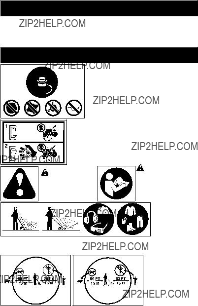
SKeep others including children, animals, by- standers, and helpers at least 50 feet (15 me- ters) away. Stop the unit immediately if you are approached.
LINE TRIMMER SAFETY
 WARNING: Inspect the area to be trimmed before each use. Remove objects
(rocks, broken glass, nails, wire, etc.) which can be thrown by or become entangled in line. Hard objects can damage the trimmer head and be thrown causing serious injury.
 WARNING: Disconnect the spark
plug before performing maintenance except carburetor adjustments.
SKeep others including children, animals, by- standers, and helpers at least 50 feet (15 me- ters) away. Bystanders should be encour-
aged to wear safety glasses. Stop engine immediately if you are approached.
SUse only for trimming, scalping, mowing and sweeping. Do not use for edging, pruning or hedge trimming.
SCut from your right to your left. Cutting on left side of the shield will throw debris away from the operator.
S Look for and replace damaged or loose parts before each use. Look for and repair fuel leaks before use. Keep in good working condition.
SHave all maintenance and service not ex- plained in this manual performed by an au-
thorized service dealer.
S Replace trimmer head parts that are chipped, cracked, broken, or damaged in any other way before using the unit.
S Maintain unit according to recommended procedures. Keep cutting line at proper length.
S Use only 0.080??? (2 mm) diameter Poulan PRO brand line. Never use wire, rope, string, etc.
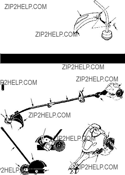
S Install required shield properly before using the unit. Use only specified trimmer head; make sure it is properly installed and se- curely fastened.
S Make sure unit is assembled correctly as shown in this manual.
S Make carburetor adjustments with lower end supported to prevent line from contact- ing any object.
S Keep others away when making carburetor adjustments.
SUse only recommended Poulan PRO ac- cessories and replacement parts.
EDGER SAFETY
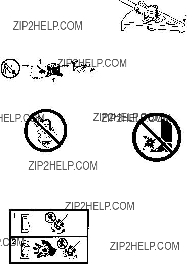
 WARNING: RISK OF CUT. KEEP
HANDS AND FEET AWAY FROM BLADE
AND CUTTING AREA. Do not attempt to clear away cut material or hold material to be cut when the blade is in motion. Make sure powerhead is stopped and spark plug wire is disconnected (or powerhead is disconnected from power source) when removing jammed
material from the cutting blade. Do not grab or hold attachment by the cutting blade.
 WARNING: Inspect the area to be edged before each use. Remove objects (rocks, broken glass, nails, wire, string, etc.) which can be thrown by the blade or can wrap around the shaft.
 WARNING: Disconnect the spark
plug before performing maintenance except carburetor adjustments.
SInspect entire unit before each use. Replace damaged parts. Check for fuel leaks. Make sure all fasteners are in place and securely
fastened.Maintain unit according to recom- mended procedures.
SHave all maintenance and service not ex- plained in this manual performed by an au- thorized service dealer.
S Throw away blades that are bent, warped, cracked, broken, or damaged in any other way. Replace parts that are cracked, chipped, or damaged before using the unit.
SUse only recommended Poulan PRO parts and accessories. Never use wire, wire
rope, string, flailing devices, etc.
SBe sure blade stops turning when engine idles (see CARBURETOR ADJUST- MENTS section of powerhead manual).
SRemove the blade before making carburetor adjustments. Hold the unit by hand. Do not make carburetor adjustments from the blade side of the unit.
SKeep others away when making carburetor adjustments.
SNever start the unit with the clutch housing re- moved. The clutch can fly off and cause seri- ous injury.
SIf blade strikes a foreign object, follow these steps: stop unit and disconnect spark plug wire (or disconnect from power source), in- spect for damage, and repair any damage be- fore resuming operation of the unit.
SNever direct discharge of material toward bystanders nor allow anyone near the area of operation. Use care in directing dis- charge to avoid glass enclosures, automo- biles, and the like.
S Always keep the wheel in contact with the ground.
SKeep all parts of your body away from the blade and muffler.
S Always push the unit slowly over the ground.
Stay alert for uneven sidewalks, holes in the terrain, large roots, etc.
SDo not force the unit. Use only for jobs ex- plained in this manual. Use only for edging.
Do not abuse unit. Do not use in rain or wet locations.
STo reduce the risk of fire, do not allow exces- sive grass, leaves, or grease to accumulate on the attachment.
S Objects struck by the cutting member can cause serious injuries to persons. The lawn should always be carefully examined and cleared of all objects prior to edging.
SNever operate without blade shield in place and in good working order.
5

 DANGER:


 ON/STOP


 Slot
Slot

 Guide slot


 Moderate (50 hours)