vent damage to unit and/or extension cord and to reduce the possibility of the extension cord disconnecting from the unit during op- eration. See ATTACH THE EXTENSION CORD TO YOUR TRIMMER in the OPERA- TION section.
S Do not attempt to repair unit. Inspect the insu-
lation and connectors on the powerhead and extension cord before each use. If there is any damage, do not use until damage is re- paired by your authorized service dealer.
SDo not use the unit if the switch does not turn the unit on and off properly. Repairs to the switch must be made by your autho-
rized service dealer.
SAvoid unintentional starting of the unit. Nev- er carry unit with your finger on the switch.
Be sure the switch is in the OFF position and never touch the switch when connect- ing extension cord.
SAvoid any body contact with any grounded conductor, such as metal fences, or pipes,
to avoid the possibility of electric shock.
S Ground Fault Circuit Interrupter (GFCI) protection should be provided on circuit or outlet to be used. Receptacles are avail-
able having built-in GFCI protection and may be used for this measure of safety.
SStop the motor immediately if you are ap- proached.
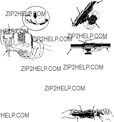
DOUBLE INSULATION CONSTRUCTION
This unit is double insulated to help protect against electric shock. Double insulation construction consists of two separate ???layers??? of electrical insulation instead of grounding. Tools built with this insulation system are not intended to be grounded. No grounding means is provided on this unit, nor should a means of grounding be added to this unit. As a result, the extension cord used with your unit
can be plugged into any standard 120 volt electrical outlet. Safety precautions must be observed when operating any electrical tool. The double insulation system only provides added protection against injury resulting from an internal electrical insulation failure.
 WARNING:
All electrical repairs to this unit, including hous- ing, switch, motor, etc., must be diagnosed and repaired by qualified service personnel. Re- placement parts for a double insulated ap- pliance must be recommended by the manufac- turer. A double insulated appliance is marked with the words ???double insulation??? or ???double in- sulated???. The symbol (square within a square)
 may also be marked on the appliance. Fail-
ure to have the unit repaired by qualified service personnel can cause the double insulation construction to become ineffective and result in serious injury.
PRUNER SAFETY
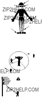
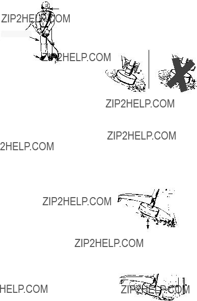
SDo not operate a pruner with one hand. Seri- ous injury to the operator, helpers, bystanders or any combination of these persons may re- sult from one-handed operation. A pruner is intended for two-handed use.
SKeep all parts of your body away from the chain when unit is running.
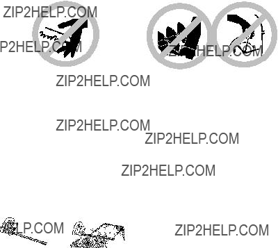
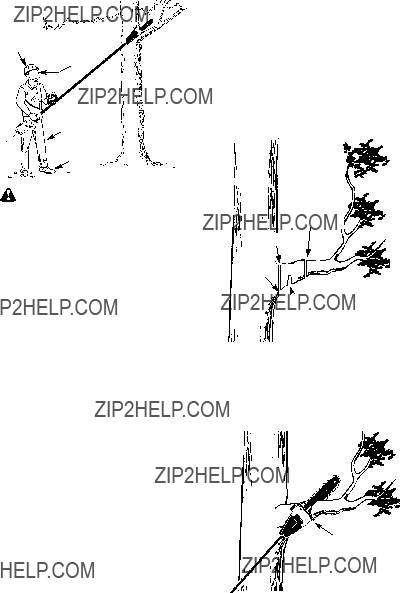
SDo not operate pruner from a ladder or in a tree.
SDo not use a pruner to cut down trees or any portion of the tree trunk.
S Only use for pruning limbs or branches
overhead not greater than 6 inches (15 cm) in diameter.
SNever stand under the limb you are pruning. Always position yourself out of the path of falling debris.
SDo not cut small brush and saplings with the pruner. Slender matter may catch in the
chain and be whipped toward you, pulling you off balance.
S Make sure the chain will not make contact
with any object while starting the unit. Never try to start the unit when the guide bar is in a cut.
S Do not force pruner. It will do the job better and safer at the rate for which it was intended.
SDo not put pressure on the pruner at the end of the cut. Applying pressure can cause you
to lose control when the cut is completed. S Do not run the unit at high speed when not
pruning.
SUse the right tool, cut wood only. Don???t use pruner for purpose not intended; for example, don???t use pruner for cutting plastic, masonry, non-wood building materials, etc.
SIf you strike or become entangled with a for- eign object, stop the unit immediately and check for damage. Have any damage re- paired by an authorized service dealer be- fore attempting further operations.
SDo not operate a pruner that is damaged, improperly adjusted, or not completely and securely assembled. Always replace bar and chain immediately if it becomes dam-
aged, broken or is otherwise removed.
SAlways stop the unit when work is delayed or when walking from one cutting location to another. Stop the motor and make sure chain has stopped moving before setting the unit
down.
SInspect cords periodically and if damaged, have repaired by an authorized service
dealer.
S Use only in daylight or good artificial light.
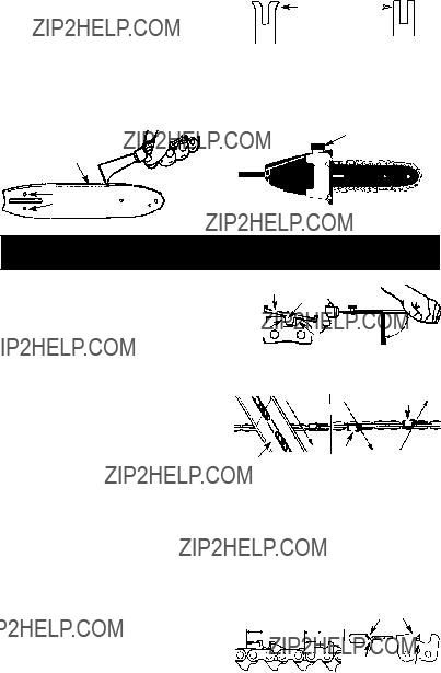
KICKBACK
 WARNING: Avoid kickback which can result in serious injury. Kickback is the backward, upward or sudden forward motion of the guide bar occurring when the chain near the upper tip of the guide bar contacts any object such as a log or branch, or when the wood closes in and pinches the chain in the cut. Contacting a foreign object in the wood can also result in loss of control.
S Rotational Kickback can occur when the
moving chain contacts an object at the upper tip of the guide bar. This contact can cause the chain to dig into the object, which stops the chain for an instant. The result is a light-
ning fast, reverse reaction which kicks the guide bar up and back toward the operator.
4


 WARNING:
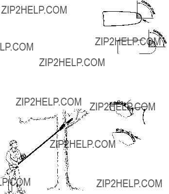

 Large Radius Tip


 Boots
Boots


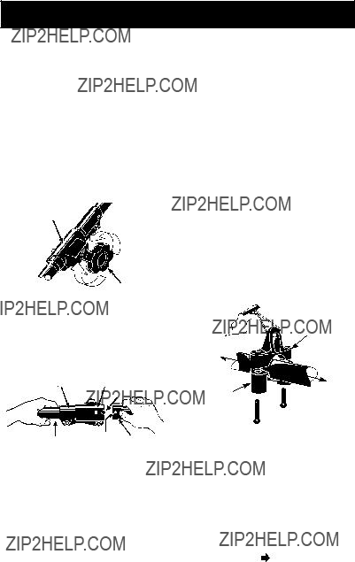


 lower arrow (closest to coupler) on the safety label to ensure proper balancing of unit. When adjusting the assist handle during use of optional attach- ments, it must be repositioned between the trig-


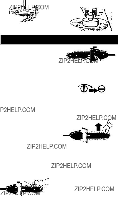


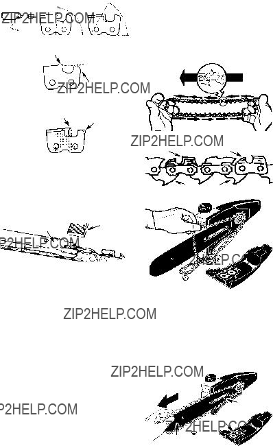

 Depth Gauge


 Holes
Holes

