R

Please do not return unit to retailer.

Por favor, no devuelva el aparato al lugar de compra. Veuillez ne pas retourner l???outil au d??taillant.

1-800-554-6723

www.poulan--pro.com

Instruction Manual

Manual de Instrucciones

Manuel d???Instructions

PP335

For Occasional Use Only

WARNING:

Read and follow all Safety Rules and Operating Instructions before using this product. Failure to do so can result in serious injury.

ADVERTENCIA:

Lea el manual de instrucciones y siga todas las advertencias e instrucciones de seguridad. El no hacerlo puede resultar en le- siones graves.

AVERTISSEMENT:

Lire le manuel d???instructions et bien respecter tous les avertisse- ments et toutes les instructions de s??curit??. Tout d??faut de le faire pourrait entra??ner des blessures graves.

ENGLISH

ESPA??OL

FRAN??AIS

TABLE OF CONTENTS

IDENTIFICATION OF SAFETY SYMBOLS

DANGER: Use only specified trimmer

head, spool, and 0.080 inch (2 mm) recommended trimmer line. Never use blades, flailing devices, wire, rope, string, etc. This attachment is designed for line trimmer use only. Failure to follow these instructions may result in serious injury.

WARNING: This unit can be dangerous! Careless or improper use can cause serious injury.

Read the operator???s manual before use. Failure to follow instructions could result in serious injury. Save operator???s manual.

Trimmer line can throw objects violently. You can be blinded or injured. Always

wear hearing protection and safety glasses marked Z87. Always wear head protection, heavy, long pants, long sleeves, boots and gloves.

Hazard zone for thrown objects.

S Trimmer line throws objects violently.

S You and others can be blinded/injured.

SKeep children, bystanders, and animals 50 feet (15 meters) away.

Secure hair above shoulder length. Do not wear jewelry, loose clothing, or

clothing with loosely hanging straps, ties, tassels, etc. They can be caught in moving parts.

2

IDENTIFICATION OF SAFETY SYMBOLS

Assist handle to be positioned only below the arrow.

Never allow children to operate this unit.

Store unit indoors in a high, dry place out of the reach of children.

When servicing unit, use only identical replacement parts.

Always stop unit and disconnect spark plug before clean- ing or servicing.

WARNING: Fire hazard. Never mix, pour, or store gasoline or

use the unit near a flame or sparks (including smoking, open flames, or work that can cause sparks).

Use unleaded gasoline and two--stroke oil mixed at a ratio of 40:1 (2.5%).

3

OPTIONAL ATTACHMENTS

These attachments used in combination with the specified powerhead have been evaluated to ANSI B175.3--2003, ???Grass Trimmers and Brushcutters -- Safety Requirements???. These combinations have been evaluated by Underwriter???s Laboratories Inc. (UL) and are conse- quently UL listed:

These attachments used in combination with the specified powerhead have been evaluated to applicable ISO-- and EN safety requirement standards by the Swedish Machinery Testing Institute:

SAFETY RULES

WARNING: When using gardening appliances, basic safety precautions must al- ways be followed to reduce the risk of fire and

serious injury. Read and follow all instructions.

This power unit can be dangerous! Operator is responsible for following instructions and warnings on unit and in manual. Read entire instruction manual before using unit! Be thor- oughly familiar with the controls and the prop- er use of the unit. Restrict the use of this unit to persons who have read, understand, and will follow the instructions and warnings on

the unit and in the manual. Never allow chil- dren to operate this unit.

DANGER: Never use blades with line

trimmer attachment. Never use flailing devices with any attachment. This unit (when used with supplied line trimmer attachment) is designed for line trimmer use only. Use of any other ac- cessories or attachments with line trimmer at- tachment will increase the risk of injury.

If situations occur which are not covered in this manual, use care and good judgment. If you need assistance, contact your authorized service dealer or call 1-800-554--6723.

OPERATOR SAFETY

SDress properly. Always wear safety glasses or similar eye protection when operating, or performing maintenance, on your unit (safety glasses are available). Eye protection should be marked Z87.

SAlways wear face or dust mask if operation is dusty.

SAlways wear heavy, long pants, long sleeves, boots, and gloves. Wearing safety leg guards

is recommended.

S Always wear foot protection. Do not go barefoot or wear sandals. Stay clear of spinning line.

SSecure hair above shoulder length. Secure or remove loose clothing or clothing with loosely hanging ties, straps, tassels, etc. They can be caught in moving parts.

S Being fully covered also helps protect you from debris and pieces of toxic plants thrown by spinning line.

SStay Alert. Do not operate this unit when you are tired, ill, upset or under the influence of

alcohol, drugs, or medication. Watch what you are doing; use common sense.

S Wear hearing protection.

S Never start or run inside a closed room or building. Breathing exhaust fumes can kill.Keep handles free of oil and fuel.

S Keep handles free of oil and fuel.

SAlways keep engine on the right hand side of your body.

SHold the unit firmly with both hands.Keep trimmer head (or other optional attachment) below waist level and away from all parts of your body. Do not raise engine above your waist.

SKeep all parts of your body away from muffler and spinning line (or other optional

attachment). Keep engine below waist level. A hot muffler can cause serious burns.

S Keep firm footing and balance. Do not

overreach or use from unstable surfaces such as ladders, trees, steep slopes, rooftops, etc.

S Use only in daylight or good artificial light.

4

SUse only for jobs explained in this manual (or manuals for optional attachments).

UNIT / MAINTENANCE SAFETY

S Disconnect the spark plug before performing maintenance except carburetor adjustments.

SLook for and replace damaged or loose parts before each use. Look for and repair fuel

leaks before use. Keep in good working condition.

SReplace trimmer head parts that are chipped, cracked, broken, or damaged in any other

way before using the unit.

S Maintain unit according to recommended procedures. Keep cutting line at proper length.

S Use only 0.115 inch (3 mm) diameter

Poulan PRO brand line. Never use wire, rope, string, etc.

SInstall required shield properly before using the unit. Use only specified trimmer head; make sure it is properly installed and securely

fastened.

S Make sure unit is assembled correctly as shown in this manual.

S Make carburetor adjustments with lower end supported to prevent line from contacting any object.

SKeep others away when making carburetor adjustments.

S Use only recommended Poulan PRO

accessories and replacement parts.

S Have all maintenance and service not explained in this manual performed by an authorized service dealer.

FUEL SAFETY

S Mix and pour fuel outdoors.

S Keep away from sparks or flames. S Use a container approved for fuel.

S Do not smoke or allow smoking near fuel or the unit.

S Avoid spilling fuel or oil. Wipe up all fuel spills.

SMove at least 10 feet (3 meters) away from fueling site before starting engine.

S Stop engine and allow to cool before

removing fuel cap.

S Always store gasoline in a container approved for flammable liquids.

TRANSPORTING AND STORAGE

S Allow engine to cool; secure unit before storing or transporting in vehicle.

S Empty the fuel tank before storing or transporting the unit. Use up fuel left in the carburetor by starting the engine and letting it

run until it stops.

SStore unit and fuel in area where fuel vapors cannot reach sparks or open flames from water heaters, electric motors or switches,

furnaces, etc.

S Store unit so line limiter blade cannot accidentally cause injury. The unit can be hung by the shaft.

S Store unit out of reach of children.

WARNING: The engine exhaust from this product contains chemicals known to the State of California to cause cancer, birth defects or other reproductive harm.

SAFETY NOTICE: Exposure to vibrations through prolonged use of gasoline powered hand tools could cause blood vessel or nerve damage in the fingers, hands, and joints of people prone to circulation disorders or abnor- mal swellings. Prolonged use in cold weather has been linked to blood vessel damage in

otherwise healthy people. If symptoms occur such as numbness, pain, loss of strength, change in skin color or texture, or loss of feeling in the fingers, hands, or joints, discontinue the use of this tool and seek medical attention. An

anti--vibration system does not guarantee the avoidance of these problems. Users who oper- ate power tools on a continual and regular basis must monitor closely their physical condition and the condition of this tool.

SPECIAL NOTICE: This unit is equipped with a temperature limiting muffler and spark ar-

resting screen which meets the requirements of California Codes 4442 and 4443. All U.S. forest land and the states of California, Idaho, Maine, Minnesota, New Jersey, Oregon, and Washing- ton require by law that many internal combus- tion engines be equipped with a spark arresting screen. If you operate in a locale where such regulations exist, you are legally responsible for maintaining the operating condition of these

parts. Failure to do so is a violation of the law. For normal homeowner use, the muffler and spark arresting screen will not require any ser- vice. After 50 hours of use, we recommend that your muffler be serviced or replaced by your au- thorized service dealer.

LINE TRIMMER SAFETY

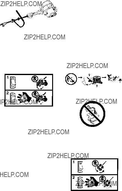
WARNING: Inspect the area before each use. Remove objects (rocks, broken glass, nails, wire, etc.) which can be thrown by or become entangled in line. Hard objects can damage the trimmer head and be thrown causing serious injury.

S Keep others including children, animals, bystanders, and helpers at least 50 feet (15

meters) away. Bystanders should be encouraged to wear safety glasses. Stop engine immediately if you are approached.

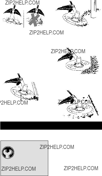
S Use only for trimming, scalping, mowing and sweeping. Do not use for edging, pruning or hedge trimming.

SCut from your left to your right. Cutting on right side of the shield will throw debris away from the operator.

ADDITIONAL SAFETY RULES

FOR OPTIONAL ATTACHMENTS

WARNING: For each optional at- tachment used, read entire instruction manu- al before use and follow all warnings and in-

structions in manual and on attachment.

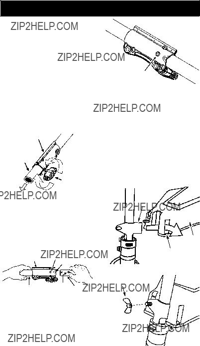
WARNING: Ensure handlebar is installed when using brushcutter attach- ments. Attach handlebar above arrow on safety label on the upper shaft (engine end of unit). If your brushcutter attachment does not include a handlebar, a handlebar accessory kit (#530071451) is available from your au- thorized service dealer.

5

Handlebar

EDGER SAFETY

WARNING: Inspect the area to be edged before each use. Remove objects (rocks, broken glass, nails, wire, etc.) which can be thrown by the blade or can wrap around the shaft.

WARNING: Blade rotates momen- tarily after the trigger is released or engine is turned off. The blade can seriously cut you or others. Allow blade to stop before removing it from the cut.

SThrow away blades that are bent, warped, cracked, broken or damaged in any other way. Replace parts that are cracked, chipped, or damaged before using the unit.

S Do not attempt to remove cut material nor hold material to be cut when the engine is running or when cutting blade is moving.

SAlways keep the wheel and depth adjusting skid in contact with the ground.

S Always push the unit slowly over the ground. Stay alert for uneven sidewalks, holes in the terrain, large roots, etc.

BLOWER/VACUUM SAFETY

WARNING: Inspect area before starting unit. Remove all debris and hard ob- jects such as rocks, glass, wire, etc. that can

ricochet, be thrown, or otherwise cause injury or damage during operation.

SDo not set unit on any surface except a clean, hard area while engine is running. Debris such as gravel, sand, dust, grass, etc., could be picked up by the air intake and thrown out through discharge opening, damaging unit,

property, or causing serious injury to bystanders or operator.

SNever place objects inside the blower tubes, vacuum tubes or blower outlet. Always direct the blowing debris away from people, animals, glass, and solid objects such as trees, automobiles, walls, etc. The force of air can cause rocks, dirt, or sticks to be thrown or to ricochet which can hurt people or animals, break glass, or cause other damage.

S Never run unit without the proper equipment attached. When using your unit as a blower, always install blower tubes.

SCheck air intake opening, blower tubes or vacuum tubes frequently, always with engine stopped and spark plug disconnected. Keep vents and discharge

tubes free of debris which can accumulate and restrict proper air flow.

SNever place any object in air intake opening as this could restrict proper air flow and cause damage to the unit.

SNever use for spreading chemicals, fertilizers, or other substances which may contain toxic

materials.

STo avoid spreading fire, do not use near leaf or brush fires, fireplaces, barbecue pits, ashtrays, etc.

BRUSHCUTTER SAFETY

DANGER: Blade can thrust violently

away from material it does not cut. Blade thrust can cause amputation of arms or legs.

WARNING: Do not use trimmer head as a fastening device for the blade.

WARNING: The blade continues to spin after the trigger is released or engine is turned off. The coasting blade can throw ob- jects or seriously cut you if accidentally

touched. Stop the blade by contacting the left hand side of the coasting blade with material already cut.

WARNING: Inspect the area to be cut before each use. Remove objects (rocks, broken glass, nails, wire, etc.) which can be thrown or become entangled in the blade or trimmer line.

6

S Throw away and replace blades that are bent, warped, cracked, broken or damaged in any other way.

SInstall required shield properly before using the unit. Use the metal shield for all metal blade use. Only use brushcutter attachments that provide a metal shield with proboscis nose.

Proboscis

nose

SUse only specified blade and make sure it is properly installed and securely fastened.

S Cut from your right to your left.

SAlways use the handlebar and a properly adjusted shoulder strap with blade (see ASSEMBLY instructions in brushcutter attachment instruction manual).

CULTIVATOR SAFETY

WARNING: Rotating tines can cause serious injury. Keep away from rotating tines. Stop the engine and disconnect the spark plug

before unclogging tines or making repairs.

WARNING: Inspect the area to be cultivated before starting the unit. Remove all debris and hard and sharp objects such as rocks, vines, branches, rope, string, etc.

S Avoid heavy contact with solid objects that might stop the tines. If heavy contact occurs, stop the engine and inspect the unit for damage.

S Never operate the cultivator without the tine

cover in place and properly secured.

S Keep the tines and guard clear of debris. S After striking a foreign object, stop the engine, disconnect the spark plug and inspect the cultivator for damage. Repair

before restarting.

SDisconnect attachment from the drive engine before cleaning the tines with a hose and water to remove any build--up. Oil the tines to prevent rust.

S Always wear gloves when servicing or cleaning the tines. The tines become very sharp from use.

S Do not run unit at high speed unless cultivating.

HEDGE TRIMMER SAFETY

DANGER: RISK OF CUT; KEEP HANDS AWAY FROM BLADE -- Blade moves momentarily after the trigger is released or en- gine is turned off. Do not attempt to clear away

cut material when the blade is in motion. Make sure the switch is in the OFF position, the spark plug wire is disconnected, and the blade has stopped moving before removing jammed ma-

terial from the cutting blade. Do not grab or hold the unit by the cutting blade.

WARNING: Inspect the area before starting the unit. Remove all debris and hard objects such as rocks, glass, wire, etc. that

can ricochet, be thrown, or otherwise cause injury or damage during operation.

S Do not use a cutting blade that is bent, warped, cracked, broken or damaged in any other way. Have worn or damaged parts replaced by an authorized service dealer.

S Always keep unit in front of your body. Keep all parts of your body away from the cutting blade.

SKeep the cutting blade and air vents clear of debris.

POLE PRUNER SAFETY

WARNING: The reciprocating blade/ rotating chain can cause severe injury. In- spect the unit before use. Do not operate unit

with a bent, cracked or dull blade or dull chain. Keep away from the blade/chain.

WARNING: The reciprocating blade/ rotating chain is sharp. Do not touch. To pre- vent serious injury, always stop engine and ensure blade/chain has stopped moving, dis- connect spark plug, and wear gloves when changing or handling the blade or chain.

WARNING: A coasting blade/rotat- ing chain can cause injury while it continues to move after the engine is stopped. Maintain

proper control of the unit until the blade/chain has completely stopped moving. Keep hands, face and feet at a distance from all moving parts. Do not attempt to touch or stop the blade or chain when it is moving.

7

WARNING: Falling objects can cause severe head injury. Wear head protec- tion when operating this unit with a pole prun-

er attachment.

WARNING: To prevent serious injury, do not use more than one boom extension with a pole pruner attachment.

WARNING: Keep the pruner away from power lines or electrical wires.

S Only use for pruning limbs or branches

overhead up to 4 inches (10 cm) in diameter. S Do not operate the unit faster than the speed needed to prune. Do not run the unit

at high speed when not pruning.

SAlways stop the unit when work is delayed or when walking from one cutting location to

another.

S If you strike or become entangled with a foreign object, stop the engine immediately

and check for damage. Have any damage repaired by an authorized service dealer before attempting further operations. Discard blades that are bent, warped, cracked or broken.

SStop the unit immediately if you feel excessive vibration. Vibration is a sign of trouble. Inspect thoroughly for loose nuts, bolts or damage before continuing. Contact an authorized service dealer for repair or replacement of affected parts as necessary.

SNOW THROWER SAFETY

WARNING: Keep hands and feet away from the rotor when starting or running the engine. Never attempt to clear the rotor

with the engine/motor running. Stop engine and disconnect spark plug before unclogging snow or debris from discharge chute or when adjusting vanes.

WARNING: Never lean over dis- charge chute. Rocks or debris could be thrown into the eyes and face and cause seri- ous injury or blindness.

WARNING: Inspect the area where

the unit is to be used. Remove objects that could be thrown or damage the unit. Some objects may be hidden by fallen snow -- be alert for the possibility.

S Direct material discharge away from glass enclosures, automobiles, etc.

S Do not run engine at high speed while not removing snow.

S Be attentive when using the snowthrower, and stay alert for holes in the terrain and other

hidden hazards.

S Make sure the rotor will spin freely before attaching the snowthrower to the powerhead.

SIf the rotor will not rotate freely due to frozen ice, thaw the unit before thoroughly before

attempting to operate under power. S Keep the rotor clear of debris.

SDo not throw snow near other people. The snow thrower could propel small objects at

high speed causing injury.

S After striking a foreign object, stop the engine, disconnect spark plug and inspect the snowthrower for damage and repair if necessary before restarting unit.

SNever operate the snowthrower near glass enclosures, automobiles and trucks.

S Never attempt to use the snowthrower on a roof.

S Never operate the snowthrower near window wells, dropoffs, etc.

SNever discharge snow onto public roads or near moving traffic.

SClear snow from slopes by going up and down; never across. Use caution when

changing directions. Never clear snow from steep slopes.

SLet snowthrower run for a few minutes after clearing snow so moving parts do not freeze.

S Look behind and use care when backing up. Exercise caution to avoid slipping or falling, especially when operating in reverse.

S Know how to stop quickly.

8

ASSEMBLY

WARNING: If received assembled, repeat all steps to ensure your unit is properly assembled and all fasteners are secure.

Examine parts for damage. Do not use dam- aged parts.

NOTE: If you need assistance or find parts missing or damaged, call 1-800-554-6723.

It is normal for the fuel filter to rattle in the empty fuel tank.

Finding fuel or oil residue on muffler is normal due to carburetor adjustments and testing done by the manufacturer.

INSTALLING TRIMMER ATTACH-

MENT

CAUTION: When installing trimmer attach- ment, place the unit on a flat surface for stabil- ity.

1.Loosen the coupler by turning the knob counterclockwise.

Coupler

Shipping

protectorLOOSEN

Knob

TIGHTEN

2.Remove shipping protector from coupler.

3.Remove the shaft cap from the trimmer at- tachment (if present).

4.Position locking/release button of attach- ment into guide recess of coupler.

5.Push the attachment into the coupler until the locking/release button snaps into the primary hole.

6.Before using the unit, tighten the knob se- curely by turning clockwise.

Coupler Primary Hole

Guide Recess

Locking/

Upper Release Attachment

Shaft Button

WARNING: Make sure the locking/ release button is locked in the primary hole and the knob is securely tightened before op- erating the unit. All attachments are designed

to be used in the primary hole unless otherwise stated in the applicable attachment instruction manual. Using the wrong hole could lead to seri- ous injury or damage to the unit.

Locking/Release

Button in Primary Hole

For assembly of optional attachments (see list on page 11), refer to the ASSEMBLY sec-

tion of the applicable attachment instruction manual.

ATTACHING THE SHIELD

WARNING: The shield must be prop- erly installed. The shield provides partial protec- tion from the risk of thrown objects to the opera- tor and others and is equipped with a line limiter blade which cuts excess line to the proper length. The line limiter blade (on underside of shield) is sharp and can cut you. For proper orientation of shield, see KNOW YOUR TRIM- MER illustration in OPERATION section.

1.Remove wing nut from shield.

2.Insert bracket into slot as shown.

3.Pivot shield until bolt passes through hole in bracket.

Bracket

Shield

Slot

4. Reinstall wing nut and tighten securely.

WingNut

9

ADJUSTING THE HANDLE

WARNING: When adjusting the han- dle, be sure it remains above the safety label and below the mark or arrow on the shaft.

1.Loosen wing nut on handle.

2.Rotate the handle on the shaft to an up- right position; retighten wing nut.

OPERATION

KNOW YOUR UNIT

READ THIS INSTRUCTION MANUAL AND SAFETY RULES BEFORE OPERATING YOUR UNIT. Compare the illustrations with your unit to familiarize yourself with the location of the various controls

and adjustments. Save this manual for future reference.

This engine is certified to operate on unleaded gasoline. Before operation, gasoline must be mixed with a good quality synthetic 2-cycle air- cooled engine oil designed to be mixed at a ratio

IMPORTANT

Use of alcohol blended fuels (called gasohol or using ethanol or methanol) can cause major en- gine performance and durability problems.

10

WARNING: Alternative fuels (not gas- oline) such as E--15 (15% alcohol), E--20 (20% alcohol), E--85 (85% alcohol) are NOT classified as gasoline and are NOT approved for use in 2--stroke gasoline engines. Use of alternative fuels will cause problems such as: improper clutch engagements, overheating, vapor lock, power loss, lubrication deficiency, deterioration

of fuel lines, gaskets and internal carburetor components, etc. Alternative fuels cause high moisture absorption into the fuel/oil mixture leading to oil and fuel separation.

HOW TO STOP YOUR UNIT

S Release the throttle trigger.

S Push and release the engine ON/STOP switch. The switch will automatically return to the ON position. Wait 5 seconds before attempting to restart unit to allow switch to reset.

ON/STOP switch

HOW TO START YOUR UNIT

WARNING: Avoid any contact with the muffler. A hot muffler can cause serious burns.

Starting position

HELPFUL TIP

If your engine still does not start after following these instructions, please call 1-800-554-6723.

STARTING A COLD ENGINE

NOTE: DO NOT squeeze the throttle trigger until the engine has started and runs.

1.Set unit on a flat surface.

2.Slowly press the primer bulb 6 times.

3.Move choke lever to the FULL CHOKE position.

Primer bulb

4.Pull starter rope handle sharply until engine sounds as if it is trying to start, but do not pull rope more than 6 times.

5.As soon as engine sounds as if it is trying to start, move choke lever to HALF CHOKE position.

6.Pull starter rope sharply until engine runs, but no more than 6 pulls. NOTE: If the en- gine doesn???t start after 6 pulls (at the HALF CHOKE position), move the choke lever to the FULL CHOKE position and press the primer bulb 6 times. Pull the starter rope 2 more times. Move the choke lever to the HALF CHOKE position and pull the starter rope until the engine runs, but no more than 6 pulls. If the en- gine still doesn???t start, it is probably flooded. Proceed to STARTING A

FLOODED ENGINE.

7.Once the engine starts, allow it to run 10 seconds. Squeeze throttle trigger and allow the unit to run for 30 more seconds at RUN. Release throttle trigger. NOTE: If engine dies with the choke lever in the RUN posi- tion, move the choke lever to FULL CHOKE then back to HALF CHOKE and pull the rope until engine runs, but no more than 6 pulls.

STARTING A WARM ENGINE

1.Move choke lever to the FULL CHOKE position, then to the HALF CHOKE posi- tion to set fast idle.

2.Pull starter rope sharply until engine runs, but no more than 6 pulls.

3.Allow engine to run 15 seconds, then move the choke lever to RUN.

NOTE: If engine has not started, pull starter rope 5 more pulls. If engine still does not run, it

is probably flooded.

STARTING A FLOODED ENGINE

Flooded engines can be started by placing the choke lever in the RUN position; then, pull the rope to clear the engine of excess fuel. This could require pulling the starter handle many times depending on how badly the unit is flooded. If the unit still doesn???t start, refer to TROUBLESHOOTING TABLE or call 1-800-554-6723.

OPERATING THE COUPLER

This model is equipped with a coupler which enables optional attachments to be installed. The optional attachments are:

MODEL:

Edger . . . . . . . . . . . . . . . . . . . . . PPB1000E Cultivator . . . . . . . . . . . . . . . . . . PPB2000T Brushcutter . . . . . . . . . . . . . . . . PPB4000C Pruner . . . . . . . . . . . . . . . . . . . . PPB5000P

Pruner . . . . . . . . . . . . . . . . . . . . PPB5500P

WARNING: Always stop unit and dis- connect spark plug before removing or instal- ling attachments.

REMOVING TRIMMER ATTACH-

MENT (OR OTHER OPTIONAL

ATTACHMENTS)

CAUTION: When removing or installing at- tachments, place the unit on a flat surface for stability.

11

1.Loosen the coupler by turning the knob counterclockwise.

Coupler

OPERATING INSTRUCTIONS

It is recommended that the engine not be operated for longer than 1 minute at full throttle.

OPERATING POSITION

AttachmentLOOSEN

Knob

TIGHTEN

2. Press and hold the locking/release button.

Locking/Release

Button

ALWAYS WEAR:

Hearing protection

Long pants

Heavy shoes

Eye protection

3.While securely holding the engine and upper shaft, pull the attachment straight out of the coupler.

INSTALLING OPTIONAL ATTACH-

MENTS

1.Remove the shaft cap from the attach- ment (if present).

2.Position locking/release button of attach- ment into guide recess of coupler.

3.Push the attachment into the coupler until the locking/release button snaps into the primary hole.

4.Before using the unit, tighten the knob se- curely by turning clockwise.

Coupler Primary Hole

Guide Recess

Locking/

Upper Release Attachment Shaft Button

WARNING: Make sure the locking/

release button is locked in the primary hole and the knob is securely tightened before op- erating the unit. All attachments are designed to be used in the primary hole unless otherwise stated in the applicable attachment instruction manual. Using the wrong hole could lead to seri- ous injury or damage to the unit.

Locking/Release

Button in Primary Hole

Cut only from your left to your right.

WARNING: Always wear eye protec- tion. Never lean over the trimmer head. Rocks or debris can ricochet or be thrown into eyes and face and cause blindness or other serious injury.

When operating unit, stand as shown and check for the following:

S Wear eye protection and heavy clothing. S Hold trigger handle with your right hand and

assit handle with left hand. S Keep unit below waist level.

S Cut only from your left to your right to ensure debris is thrown away from you. Without bending over, keep line near and

parallel to the ground and not crowded into material being cut.

Do not run the engine at a higher speed than necessary. The cutting line will cut efficiently when the engine is run at less than full throttle.

At lower speeds, there is less engine noise and vibration. The cutting line will last longer and will be less likely to ???weld??? onto the spool. Always release the throttle trigger and allow the en- gine to return to idle speed when not cutting.

To stop engine:

S Release the throttle trigger.

S Push and release the engine ON/STOP switch.

CUTTING METHODS

WARNING: Use minimum speed and do not crowd the line when cutting around hard objects (rock, gravel, fence posts, etc.), which can damage the trimmer head, become

entangled in the line, or be thrown causing a serious hazard.

SThe tip of the line does the cutting. You will achieve the best performance and mini- mum line wear by not crowding the line into the cutting area. The right and wrong ways are shown below.

12

S The line will easily remove grass and weeds from around walls, fences, trees and flower beds, but it also can cut the tender bark of trees or shrubs and scar fences.

S For trimming or scalping, use less than full

throttle to increase line life and decrease head wear, especially:

S During light duty cutting.

S Near objects around which the line can wrap such as small posts, trees or fence wire.

SFor mowing or sweeping, use full throttle for a good clean job.

TRIMMING -- Hold the bottom of the trimmer head about 3 inches (8 cm) above the ground

and at an angle. Allow only the tip of the line to make contact. Do not force trimmer line into work area.

Trimming

3 inches (8 cm) above ground

SCALPING -- The scalping technique removes unwanted vegetation down to the ground. Hold the bottom of the trimmer head about 3 in. (8 cm) above the ground and at an angle. Allow the tip of the line to strike the ground around trees, posts, monuments, etc. This technique in- creases line wear.

MOWING -- Your trimmer is ideal for mowing

in places conventional lawn mowers cannot reach. In the mowing position, keep the line parallel to the ground. Avoid pressing the head into the ground as this can scalp the ground and damage the tool.

Mowing

SWEEPING -- The fanning action of the rotat- ing line can be used to blow away loose debris from an area. Keep the line parallel to and

above the area surface and swing the tool from side to side.

Sweeping

MAINTENANCE

WARNING: Disconnect the spark plug before performing maintenance except for carburetor adjustments.

HELPFUL TIP

IMPORTANT: Have all

repairs other than the rec- ommended maintenance

described in the instruction manual performed by an

authorized service dealer.

If any dealer other than an authorized service dealer performs work on the product, Poulan PRO may not pay for

repairs under warranty. It is your re- sponsibility to maintain and perform

general maintenance.

CHECK FOR LOOSE

FASTENERS AND PARTS

S Spark Plug Boot

S Air Filter

S Housing Screws

S Assist Handle Screw

S Debris Shield

CHECK FOR DAMAGED OR

WORN PARTS

Contact an authorized service dealer for re- placement of damaged or worn parts.

S ON/STOP Switch -- Ensure ON/STOP switch functions properly by pushing and releasing the switch. Make sure engine stops. Wait 5 seconds before attempting to restart unit to allow switch to reset. Restart engine and continue.

13

SFuel Tank -- Discontinue use of unit if fuel tank shows signs of damage or leaks.

SDebris Shield -- Discontinue use of unit if debris shield is damaged.

INSPECT AND CLEAN UNIT AND

DECALS

S After each use, inspect complete unit for loose or damaged parts. Clean the unit and decals using a damp cloth with a mild deter- gent.

S Wipe off unit with a clean dry cloth.

CLEAN AIR FILTER

A dirty air filter decreases engine perform- ance and increases fuel consumption and harmful emissions. Always clean after every 5 hours of operation.

1. Clean the cover and the area around it to keep dirt from falling into the carburetor chamber when the cover is removed.

2. Loosen bolt with a 5/16 inch (8 mm) socket wrench. Remove air filter cover and air filter.

NOTE: To avoid creating a fire hazard or

producing harmful evaporative emissions, do not clean filter in gasoline or other flammable solvent.

3.Wash the filter in soap and water.

4.Allow filter to dry.

5.Replace parts.

Bolt

INSPECT MUFFLER AND SPARK

ARRESTING SCREEN

WARNING: The muffler on this prod- uct contains chemicals known to the State of California to cause cancer.

As your unit is used, carbon deposits build up

on the muffler and spark arresting screen and must be removed to avoid creating a fire haz- ard or affecting engine performance.

For normal homeowner use, the muffler and spark arresting screen will not require any

service. After 50 hours of use, we recom- mend that your muffler be serviced or re- placed by an authorized service dealer.

REPLACE SPARK PLUG

Replace the spark plug each year to ensure the engine starts easier and runs better. In- spect spark plug every 25 hours of usage. Clean and/or replace as necessary. Set spark plug gap at 0.025 inch (0.6 mm). Ignition tim- ing is fixed and nonadjustable.

1.Twist, then pull off spark plug boot.

2.Remove spark plug from cylinder and discard.

3.Replace with Champion RCJ-6Y spark plug and tighten securely with a 3/4 inch (19 mm) socket wrench.

4.Reinstall the spark plug boot.

SERVICE AND ADJUSTMENTS

REPLACING THE LINE

For unit to operate properly, the cutting line should be replaced when line becomes worn to less than 3 inches in length from the edge of the line exit tunnels on each side of the cutting head.

1.Remove and discard worn line before installing new line.

2.Use only 0.115 inch (3 mm) diameter Poulan PRO brand cut length line.

3.Insert one end of the line through the positioning tunnel.

4.Continue to feed line through tunnel until line is centered (leaving equal amounts on each side). See illustration below.

Positioning

tunnel

5.Insert ends of line one at a time through the line exit tunnels.

6.Pull the line and make sure the line is ex- tended fully through the tunnels.

7.Correctly installed line will be the same length on both ends.

REPLACING THE CUTTING HEAD

1.Align hole in the dust cup with the hole in the side of the gearbox by rotating the dust cup.

2.Insert a small screwdriver into aligned holes. This will keep the shaft from turning while removing and installing trimmer head.

14

Screwdriver

3.While holding the screwdriver in position, remove trimmer head by turning clock- wise (looking from bottom of unit).

4.Thread replacement trimmer head onto the shaft by turning counterclockwise. Tighten until secure.

5.Remove the screwdriver.

CARBURETOR IDLE SPEED

ADJUSTMENT

WARNING: Keep others away when

making idle speed adjustments. The trimmer head, blade or any optional attachment will be spinning during most of this procedure. Wear your protective equipment and observe all safe- ty precautions. After making adjustments, the trimmer head, blade or any optional attachment must not move/spin at idle speed.

The carburetor has been carefully set at the factory. Adjustments may be necessary if you notice any of the following conditions:

S Engine will not idle when the throttle is released.

S The trimmer head, blade or optional attachment moves/spins at idle.

Make adjustments with the unit supported so the cutting attachment is off the ground and will not make contact with any object. Hold the unit by hand while running and making ad- justments. Keep all parts of your body away

from the cutting attachment and muffler.

To adjust idle speed:

Allow engine to idle. Adjust speed until engine runs without trimmer head, blade or optional attachment moving or spinning (idle too fast) or stalling (idle speed too slow).

S Turn idle speed screw clockwise to increase engine speed if engine stalls or dies.

STurn idle speed screw counterclockwise to decrease engine speed if trimmer head, blade or optional attachment moves or spins at idle.

WARNING: Recheck the idle speed after each adjustment. The trimmer head, blade or optional attachment must not move or spin at idle speed to avoid serious injury to the operator or others.

Idle Speed Screw

Air Filter

Cover

If you require further assistance or are unsure about performing this procedure, contact an authorized service dealer or call

1--800--554--6723.

STORAGE

WARNING: Perform the following steps after each use:

S Allow engine to cool before storing or trans- porting.

SStore unit and fuel in a well ventilated area where fuel vapors cannot reach sparks or open flames from water heaters, electric motors or switches, furnaces, etc.

S Store unit with all guards in place. Position unit so that any sharp object cannot acci- dentally cause injury.

SStore unit and fuel well out of the reach of children.

SEASONAL STORAGE

Prepare unit for storage at end of season or if it will not be used for 30 days or more.

If your unit is to be stored for a period of time: S Clean the entire unit before lengthy storage. S Store in a clean dry area.

S Lightly oil external metal surfaces.

FUEL SYSTEM

Under FUELING ENGINE in the OPERA- TION section of this manual, see message la- beled IMPORTANT regarding the use of ga- sohol in your engine.

Fuel stabilizer is an acceptable alternative in minimizing the formation of fuel gum deposits during storage. Add stabilizer to the gasoline in the fuel tank or fuel storage container.

Follow the mix instructions found on stabilizer container. Run engine at least 5 minutes after adding stabilizer.

HELPFUL TIP

During storage of your gas/

oil mixture, the oil will sepa- rate from the gas.

We recommend that you shake the gas can weekly to insure proper blending of the gas and oil.

15

ENGINE

SRemove spark plug and pour 1 teaspoon of 40:1, 2-cycle engine oil (air cooled) through

the spark plug opening. Slowly pull the starter rope 8 to 10 times to distribute oil.

S Replace spark plug with new one of recom-

mended type and heat range. S Clean air filter.

S Check entire unit for loose screws, nuts, and bolts. Replace any damaged, broken, or worn parts.

SAt the beginning of the next season, use only fresh fuel having the proper gasoline to oil ratio.

OTHER

SDo not store gasoline from one season to another. Replace your gasoline can if it starts to rust.

TROUBLESHOOTING TABLE

WARNING: Always stop unit and disconnect spark plug before performing all of the recommended remedies below except remedies that require operation of the unit.

16

LIMITED WARRANTY

Poulan PRO, a division of Husqvarna Consumer Outdoor Products N.A., Inc., war- rants to the original consumer purchaser that each new Poulan PRO brand gasoline tool or attachment is free from defects in material and workmanship and agrees to repair or replace under this warranty any defective gasoline prod-

uct or attachment as follows from the original date of purchase.

2 YEARS - Parts and Labor, when used for household purposes.

90 DAYS - Parts and Labor, when used for

commercial, professional, or income producing purposes.

30 DAYS - Parts and Labor, if used for rental purposes.

This warranty is not transferable and does not cover damage or liability caused by improper handling, improper maintenance or alteration, or the use of accessories and/or attachments not specifically recommended by Poulan PRO for this tool. This warranty does not cover tune--up, spark plugs, filters, starter ropes, cutting line, or rotating head parts that will wear and require re- placement with reasonable use during the war- ranty period. This warranty does not cover pre--

delivery setup or normal adjustments explained in the instruction manual. This warranty does not cover transportation costs.

In the event you have a claim under this warran- ty, you must return the product to an authorized service dealer.

Should you have any unanswered questions concerning this warranty, please contact: Poulan PRO, a division of Husqvarna Consumer Outdoor Products N.A., Inc.

7349 Statesville Road

Charlotte, NC 28269 1--800--554--6723

In Canada, contact:

Poulan PRO

850 Matheson Blvd. West Mississauga, Ontario L5V 0B4

Giving the model number, serial number and date of purchase of your product and the name and address of the authorized dealer from whom it was purchased.

THIS WARRANTY GIVES YOU SPECIFIC

LEGAL RIGHTS, AND YOU MAY HAVE OTH-

ER RIGHTS WHICH VARY FROM STATE TO

STATE.

NO CLAIMS FOR CONSEQUENTIAL OR

OTHER DAMAGES WILL BE ALLOWED,

AND THERE ARE NO OTHER EXPRESS

WARRANTIES EXCEPT THOSE EX-

PRESSLY STIPULATED HEREIN.

SOME STATES DO NOT ALLOW LIMITA-

TIONS ON HOW LONG AN IMPLIED WAR-

RANTY LASTS OR THE EXCLUSION OR

LIMITATIONS OF INCIDENTAL OR CONSE-

QUENTIAL DAMAGES, SO THE ABOVE LIM-

ITATIONS OR EXCLUSION MAY NOT APPLY

TO YOU.

This is a limited warranty within the meaning of that term as defined in the Magnuson--Moss Act of 1975.

The policy of Poulan PRO is to continuously improve its products. Therefore, Poulan PRO reserves the right to change, modify, or discontinue models, designs, specifications,

and accessories of all products at any time without notice or obligation to any purchaser.

U.S. EPA / CALIFORNIA / ENVIRONMENT CANADA

EMISSION CONTROL WARRANTY STATEMENT

YOUR WARRANTY RIGHTS AND OB-

LIGATIONS: The U.S. Environmental

Protection Agency, California Air Resources Board, Environment Canada and Poulan PRO are pleased to explain the emissions con- trol system warranty on your year 2009 and lat- er small off--road engine. In California, all small

off--road engines must be designed, built, and equipped to meet the State???s stringent anti-- smog standards. Poulan PRO must warrant the emission control system on your small off--road engine for the periods of time listed below provided there has been no abuse, ne- glect, or improper maintenance of your small off--road engine. Your emission control system includes parts such as the carburetor, the igni- tion system and the fuel tank. Where a warrant-

able condition exists, Poulan PRO will repair your small off--road engine at no cost to you. Expenses covered under warranty include diagnosis, parts and labor.

MANUFACTURER???S WARRANTY COV- ERAGE: If any emissions related part on your

engine (as listed under Emissions Control Warranty Parts List) is defective or a defect in the materials or workmanship of the engine causes the failure of such an emission related part, the part will be repaired or replaced by

Poulan PRO. OWNER???S WARRANTY RE- SPONSIBILITIES: As the small off--road en- gine owner, you are responsible for the per- formance of the required maintenance listed in your instruction manual. Poulan PRO rec- ommends that you retain all receipts covering maintenance on your small off--road engine, but Poulan PRO cannot deny warranty solely for the lack of receipts or for your failure to en- sure the performance of all scheduled main-

tenance. As the small off--road engine owner, you should be aware that Poulan PRO may deny you warranty coverage if your small off-- road engine or a part of it has failed due to

17

abuse, neglect, improper maintenance, un- approved modifications, or the use of parts not made or approved by the original equip- ment manufacturer. You are responsible for presenting your small off--road engine to an Poulan PRO authorized repair center as soon as a problem exists. Warranty repairs should be

completed in a reasonable amount of time, not to exceed 30 days. If you have any questions regarding your warranty rights and responsi- bilities, you should contact your nearest autho- rized service center, call Poulan PRO at 1--800--554--6723, or send e-mail correspon- dence to emission.warranty@HCOP-- emission.com. WARRANTY COM- MENCE- MENT DATE: The warranty period begins on the date the small off--road engine is pur-

chased. LENGTH OF COVERAGE: This warranty shall be for a period of two years from the initial date of purchase. WHAT IS

COVERED: REPAIR OR REPLACEMENT OF PARTS. Repair or replacement of any warranted part will be performed at no charge to the owner at an approved Poulan PRO servicing center. If you have any questions regarding your warranty rights and responsi-

bilities, you should contact your nearest au- thorized service center, call Poulan PRO at 1--800--554--6723, or send e-mail correspon- dence to emission.warranty@HCOP-- emission.com. WARRANTY PERIOD: Any warranted part which is not scheduled for re- placement as required maintenance, or which is scheduled only for regular inspection to the effect of ???repair or replace as necessary??? shall be warranted for 2 years. Any warranted part

which is scheduled for replacement as required maintenance shall be warranted for the period of time up to the first scheduled replacement point for that part. DIAGNOSIS: The owner shall not

be charged for diagnostic labor which leads to the determination that a warranted part is defec-

tive if the diagnostic work is performed at an ap- proved Poulan PRO servicing center. CONSE- QUENTIAL DAMAGES: Poulan PRO may be liable for damages to other engine components caused by the failure of a warranted part still un- der warranty. WHAT IS NOT COVERED: All failures caused by abuse, neglect, or improper

maintenance are not covered. ADD-ON OR MODIFIED PARTS: The use of add--on or modified parts can be grounds for disallowing a warranty claim. Poulan PRO is not liable to cover failures of warranted parts caused by the use of add--on or modified parts.

HOW TO FILE A CLAIM: If you have any questions regarding your warranty rights and responsibilities, you should contact your nearest authorized service center, call Pou-

lan PRO at 1--800--554--6723, or send e-mail correspondence to emission.warranty @HCOP--emission.com. WHERE TO GET WARRANTY SERVICE: Warranty services

or repairs shall be provided at all Poulan PRO service centers. Call: 1--800--554--6723 or send e-mail correspondence to emission. warranty@HCOP--emission.com. MAINTE-

NANCE, REPLACEMENT AND REPAIR

OF EMISSION RELATED PARTS: Any Pou- lan PRO approved replacement part used in the performance of any warranty mainte- nance or repair on emission related parts will be provided without charge to the owner if the

part is under warranty. EMISSION CON- TROL WARRANTY PARTS LIST: Carbure- tor, air filter (covered up to maintenance schedule), ignition system: spark plug (cov- ered up to maintenance schedule), ignition module, muffler including catalyst (if equipped), fuel tank. MAINTENANCE STATEMENT: The owner is responsible for the performance of all required maintenance

as defined in the instruction manual.

The information on the product label indicates which standard your engine is certified. Example: (Year) EPA and/or CALIFORNIA.

This engine is certified to be emissions compliant for the following use: Moderate (50 hours)

Intermediate (125 hours) Extended (300 hours)

18