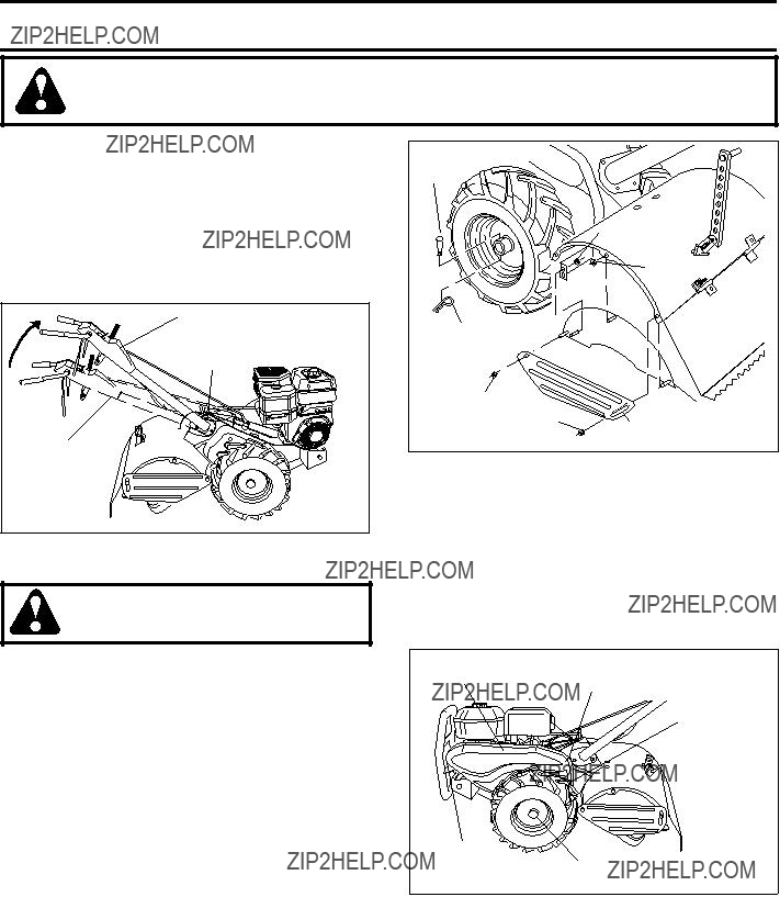
???Swing the handle in the opposite direction you wish to turn, being careful to keep feet and legs away from tines.
???When you have completed your turn-around, release the drive control bar and lower handle. Place shift lever in till position and move throttle control to desired speed. To begin tilling, hold drive control bar against the handle.
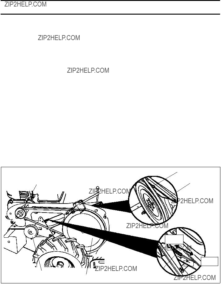
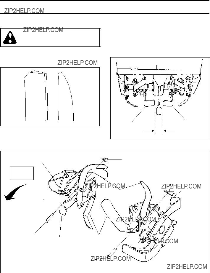
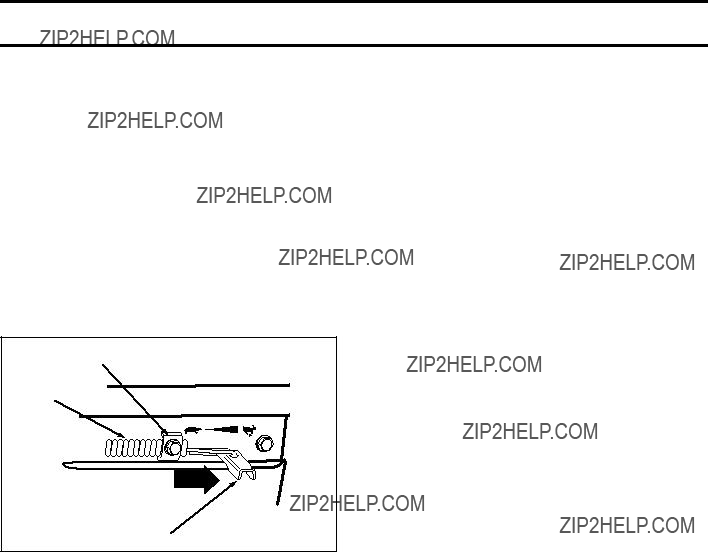
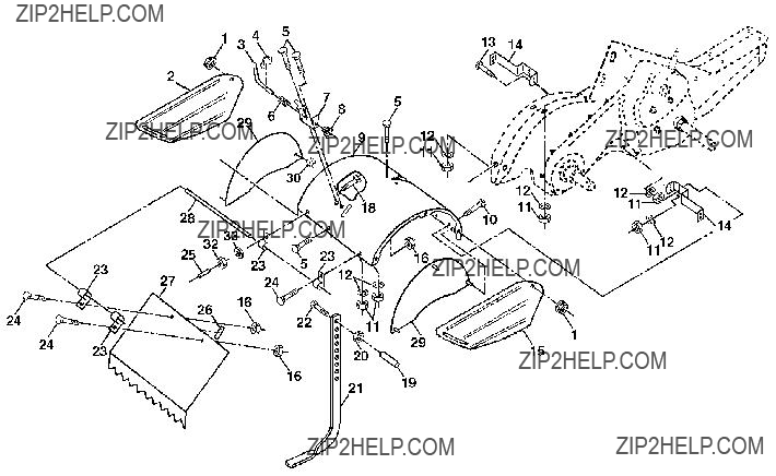
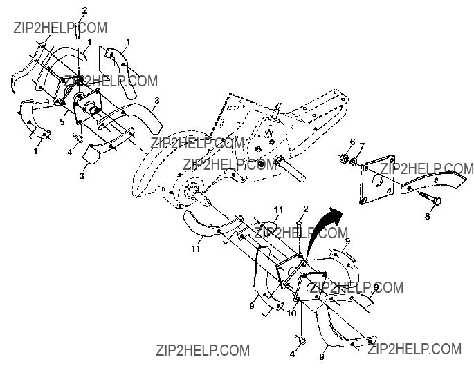
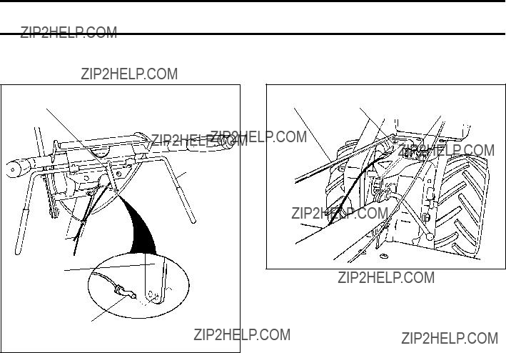
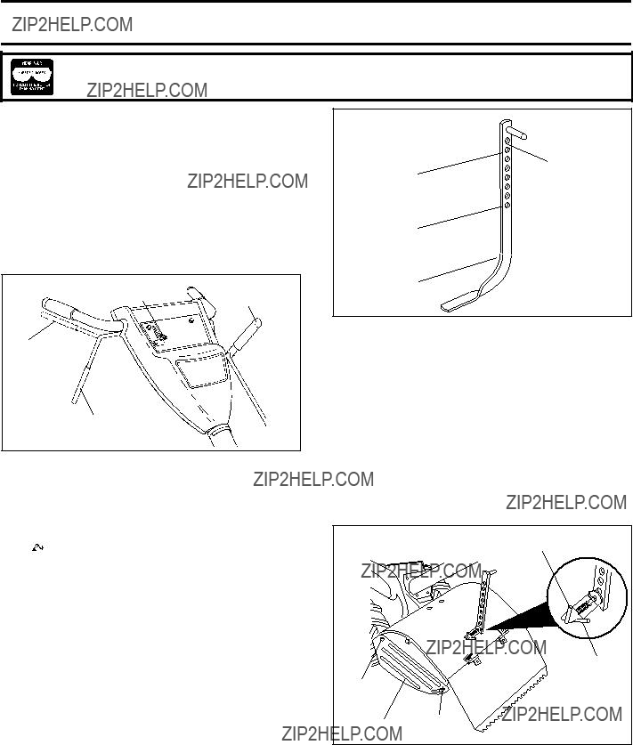
OUTER SIDE SHIELDS (See Fig. 11)
The back edges of the outer side shields are slotted so that the shields can be raised for deep tilling and lowered for shallow tilling to protect small plants from being buried. Loosen nut ???A??? in slot and nut ???B???. Move shield to desired position (both sides). Retighten nuts.
TO TRANSPORT
CAUTION: Before lifting or transporting, allow tiller engine and muf???er to cool. Disconnect spark plug wire. Drain gasoline from fuel tank.
AROUND THE YARD
???Release the depth stake pin. Move the depth stake down to the top hole for transporting the tiller. Place depth stake pin in hole of depth stake to lock in posi- tion. This prevents tines from scuf???ng the ground.
???Place shift lever indicator in ???F??? (forward) position for transporting.
???Hold the drive control bar against the handle to start tiller movement. Tines will not turn.
???Move throttle control to desired speed.
AROUND TOWN
???Disconnect spark plug wire.
???Drain fuel tank.
???Transport in upright position to prevent oil leakage.
BEFORE STARTING ENGINE
IMPORTANT: BE VERY CAREFUL NOT TO ALLOW DIRT
TO ENTER THE ENGINE WHEN CHECKING OR ADDING
OIL OR FUEL. USE CLEAN OIL AND FUEL AND STORE IN
APPROVED, CLEAN, COVERED CONTAINERS. USE CLEAN
FILL FUNNELS.
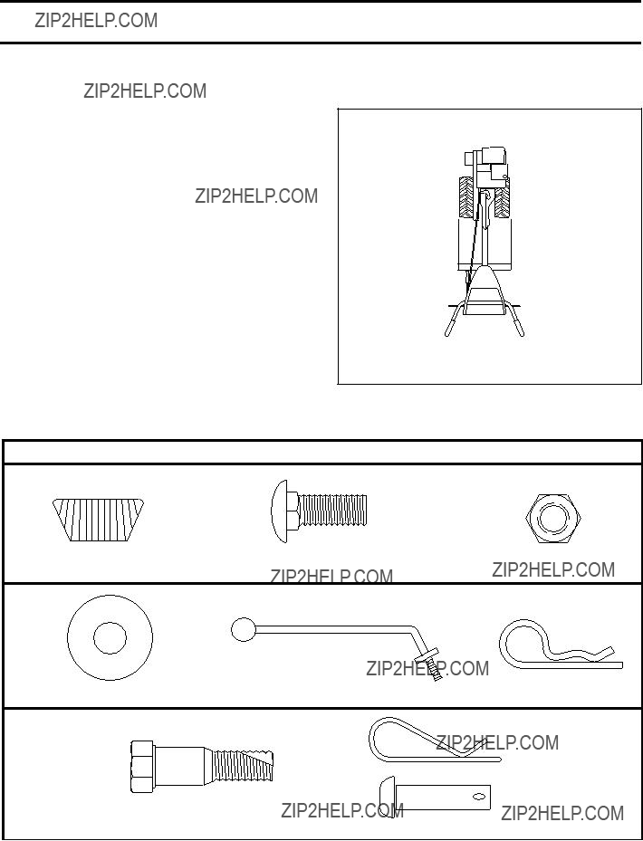
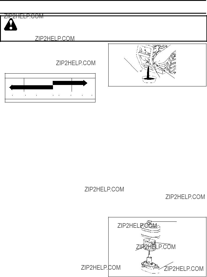
CHECK ENGINE OIL LEVEL (See Fig. 12)
???The engine in your unit has been shipped, from the factory, already ???lled with SAE 30 summer weight oil.
???With engine level, clean area around oil ???ller plug and remove plug.
???Engine oil should be to point of over???owing when engine is level. For approximate capacity see ???PRODUCT SPECIFICATIONS??? on page 3 of this manual. All oil must meet A.P.I. Service Classi???cation SF-SJ.
???Reinstall engine oil cap and tighten.
???For cold weather operation you should change oil for easier starting (See oil viscosity chart in the Mainte- nance section of this manual).
???To change engine oil, see the Maintenance section in this manual.
OIL
LEVEL 
FIG. 12
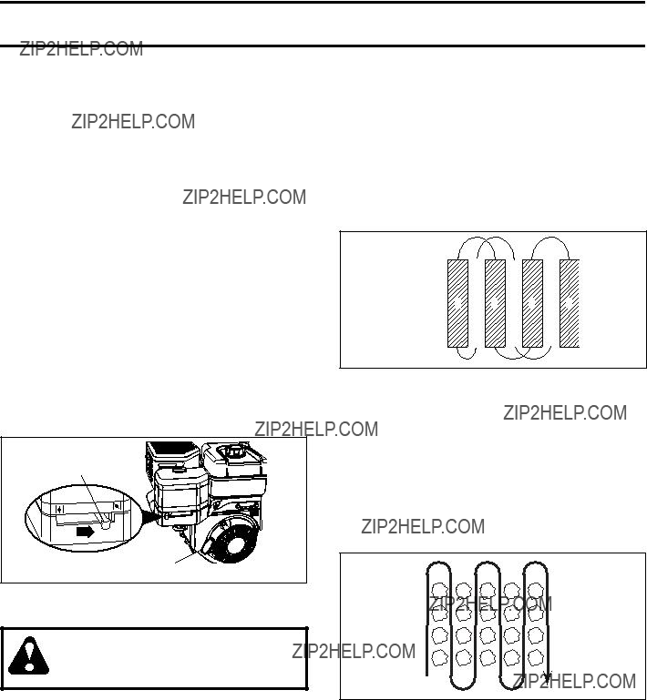
ADD GASOLINE
???Fill fuel tank to bottom of ???ller neck. Do not over???ll. Use fresh, clean, regular unleaded gasoline with a minimum of 87 octane. (Use of leaded gasoline will increase carbon and lead oxide deposits and reduce valve life). Do not mix oil with gasoline. Purchase fuel in quantities that can be used within 30 days to assure fuel freshness.
CAUTION: Fill to within 1/2 inch of top of fuel tank to prevent spills and to allow for fuel expansion. If gasoline is ac- cidentally spilled, move machine away from area of spill. Avoid creating any source of ignition until gasoline vapors have disappeared.
Wipe off any spilled oil or fuel. Do not store, spill or use gasoline near an open ???ame.
IMPORTANT: WHEN OPERATING IN TEMPERATURES BELOW32??F(0??C), USE FRESH, CLEAN WINTER GRADE
GASOLINE TO HELP INSURE GOOD COLD WEATHER
STARTING.
CAUTION: Alcohol blended fuels (called gasohol or using ethanol or methanol) can at- tract moisture which leads to separation and formation of acids during storage. Acidic gas can damage the fuel system of an engine while in storage. To avoid engine problems, the fuel system should be emptied before storage of 30 days or longer. Drain the gas tank, start the engine and let it run until the fuel lines and carburetor are empty. Use fresh fuel next season. See Storage Instructions for additional information. Never use engine or carburetor cleaner products in the fuel tank or permanent damage may occur.
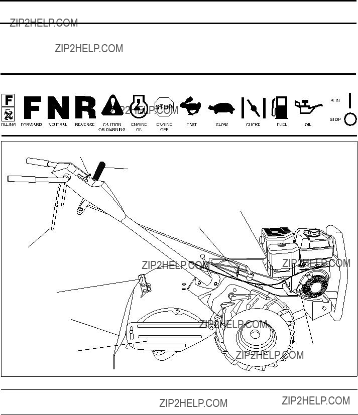
TO START ENGINE (See Fig. 13)
CAUTION: Keep drive control bar in ???DISENGAGED??? position when start- ing engine.
When starting engine for the ???rst time or if engine has run out of fuel, it will take extra pulls of the recoil starter to move fuel from the tank to the engine.
 WARNING:
 WARNING

 RIGHT
RIGHT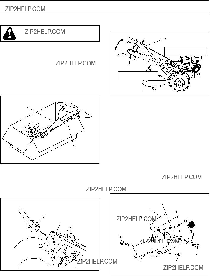
 ) till position and engaging drive control bar.
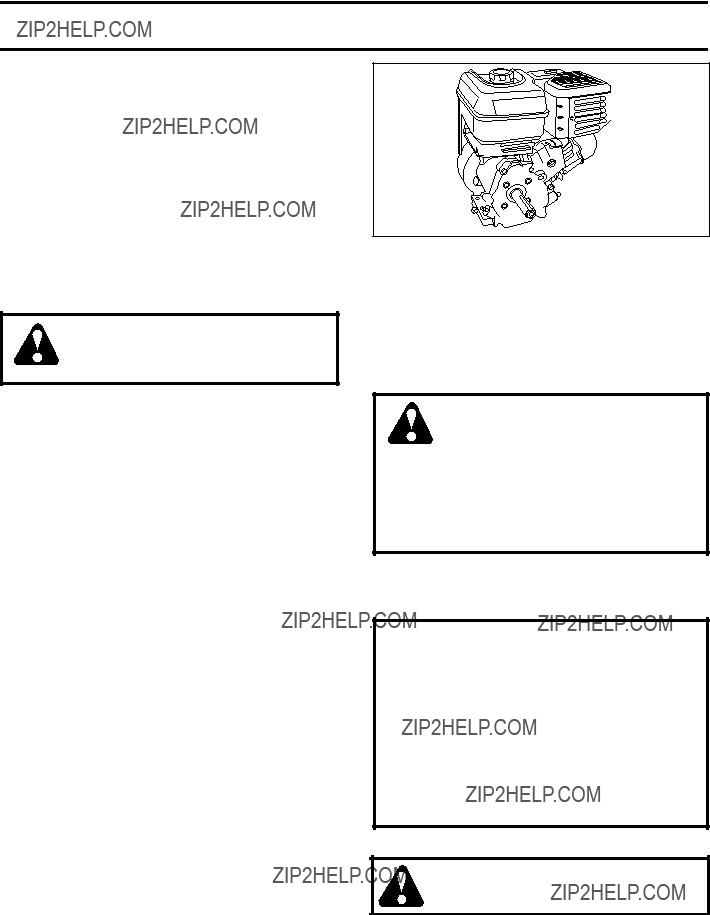
 COVER
COVER