SAFETY RULES
Safe Operation Practices for Snow Throwers
IMPORTANT: This machine is capable of amputating hands and feet and throwing objects. Failure to observe the following safety instructions could result in serious injury or death.
Look for this symbol to point out im- portant safety precautions. It means CAUTION!!! BECOME ALERT!!! YOUR
SAFETY IS INVOLVED.
WARNING: Always disconnect spark plug wire and place it where it cannot contact plug in order to prevent acci- dental starting when setting up, trans- porting, adjusting or making repairs.
WARNING: This snow thrower is for use on sidewalks, driveways and other ground level surfaces. Caution should be exercised while using on sloping surfaces. Do not use snow thrower on surfaces above ground level such as roofs of residences, garages, porches or other such structures or buildings.
WARNING: Snow throwers have ex- posed rotating parts, which can cause severe injury from contact, or from ma- terial thrown from the discharge chute. Keep the area of operation clear of all persons, small children and pets at all times including startup.
CAUTION: Muf???er and other engine parts become extremely hot during operation and remain hot after engine has stopped.To avoid severe burns on contact, stay away from these areas.
WARNING: Engine exhaust, some of its constituents, and certain vehicle components contain or emit chemi- cals known to the State of California to cause cancer and birth defects or other reproductive harm.
TRAINING
???Read the operating and service instruction manual carefully. Be thoroughly familiar with the controls and the proper use of the equipment. Know how to stop the unit and disengage the controls quickly.
???Never allow children to operate the equipment. Never allow adults to operate the equipment without proper instruction.
???Keep the area of operation clear of all persons, par- ticularly small children and pets.
???Exercise caution to avoid slipping or falling especially when operating in reverse.
PREPARATION
???Remove foreign objects. Thoroughly inspect the area where the equipment is to be used and remove all doormats, sleds, boards, wires, rocks & landscaping.
???Disengage all clutches before starting engine (mo- tor).
???Do not operate the equipment without wearing ade- quate winter outer garments. Avoid loose, dangling clothing, such as scarves, which can get caught in rotating parts. Wear footwear that will improve footing on slippery surfaces.
???Handle fuel with care; it is highly ??? ammable.
-Never smoke while refueling.
-Use an approved fuel container.
-Never remove fuel tank cap or add fuel to a running engine (motor) or hot engine (motor).
-Fill fuel tank outdoors with extreme care. Never ??? ll fuel tank indoors.
-Replace fuel cap securely and wipe up spilled fuel.
-Never store fuel or snow thrower with fuel in the tank inside of a building where fumes may reach an open ??? ame or spark.
-Check fuel supply before each use, allowing space for expansion as the heat of the engine (motor) and/or sun cause fuel to expand.
STATIC ELECTRICITY HAZARD -
-Never ??? ll containers inside a vehicle or on a truck or trailer bed with a plastic liner. Always place containers on the ground, away from your vehicle before ??? lling.
-When practical, remove gas-powered equipment from the truck or trailer and refuel it on the ground. If this is not possible, then refuel such equipment on a trailer with a portable container, rather than from a gasoline dispenser nozzle.
-Keep the nozzle in contact with the rim of the fuel tankopening at all times, until refueling is complete. Do not use a nozzle lock-open device.
-If fuel is spilled on clothing, change clothing im- mediately.
???For all units with electric starting motors use electric starting extension cords certi??? ed CSA/UL. Use only with a receptacle that has been installed in accordance with local inspection authorities.
???If snow thrower must be operated over gravel surface, use extra caution and be sure skid plates are adjusted to lowest (highest scraper clearance) position.
???Never attempt to make any adjustments while the engine (motor) is running (except when speci??? cally recommended by manufacturer).
???Let engine (motor) and snow thrower adjust to outdoor temperatures before starting to clear snow.
???Always wear safety glasses or eye shields during op- eration or while performing an adjustment or repair to protect eyes from foreign objects that may be thrown from the snow thrower.
OPERATION
???Do not operate this machine if you are under the in??? u- ence of alcohol or taking drugs or other medication which can cause drowsiness or affect your ability to operate this machine.
???Do not use this machine if you are mentally or physically unable to operate this machine safely.
PARTS PACKED SEPARATELY IN CARTON
ASSEMBLY / PRE-OPERATION
Read these instructions and this manual in its entirety before you attempt to assemble or operate your new snow thrower.
Your new snow thrower has been assembled at the factory with the exception of those parts left unassembled for shipping purposes. All parts such as nuts, washers, bolts, etc., necessary to complete the assembly have been placed in the parts bag. To ensure safe and proper operation of your snow thrower, all parts and hardware you assemble must be tightened securely. Use the correct tools as necessary to ensure proper tightness.
REMOVE SNOW THROWER FROM CARTON
1.Remove all accessible loose parts and parts boxes from carton.
2.Cut down all four corners of carton and lay panels ??? at.
3.Remove all packing materials except plastic tie holding speed control rod to lower handle.
4.Remove snow thrower from carton and check carton thoroughly for additional loose parts.
HOW TO SET UP YOUR SNOW THROWER
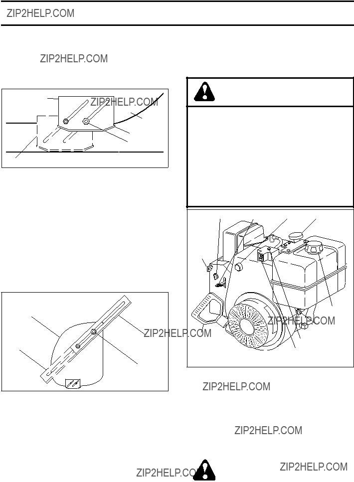
TOOL BOX (See Fig. 10)
A toolbox is provided on your snow thrower. The toolbox is located on top of the belt cover. Store the extra shear bolts, nuts and multi-wrench provided in parts bag in the toolbox.
NOTE: The multi-wrench may be used for assembly of the chute rotator head to snow thrower and making adjustments to the skid plates.
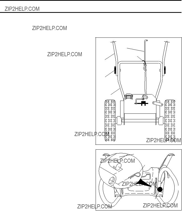
UNFOLD UPPER HANDLE
1.Raise upper handle to the operating position and tighten handle knobs securely.
INSTALL SPEED CONTROL ROD (See Figs. 1 and 2)
1.Remove plastic tie securing rod to lower handle.
2.Insert rod into speed control bracket and secure with retainer spring.
FIG. 1
SPEED CONTROL ROD
RETAINER
SPRING
SPEEDSPEED
CONTROL CONTROL
BRACKET LEVER
FIG. 2
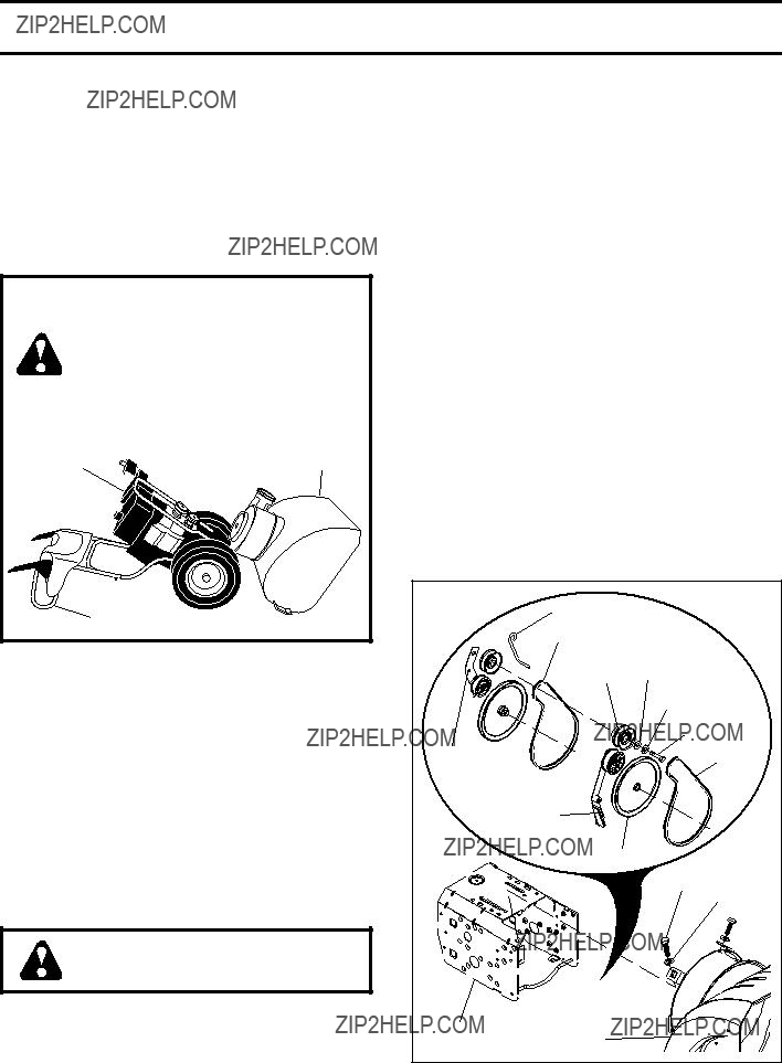
OPERATION
KNOW YOUR SNOW THROWER
READ THIS OWNER'S MANUAL AND ALL SAFETY RULES BEFORE OPERATING YOUR SNOW THROWER. Compare the illustrations with your snow thrower to familiarize yourself with the location of various controls and adjustments. Save this manual for future reference.
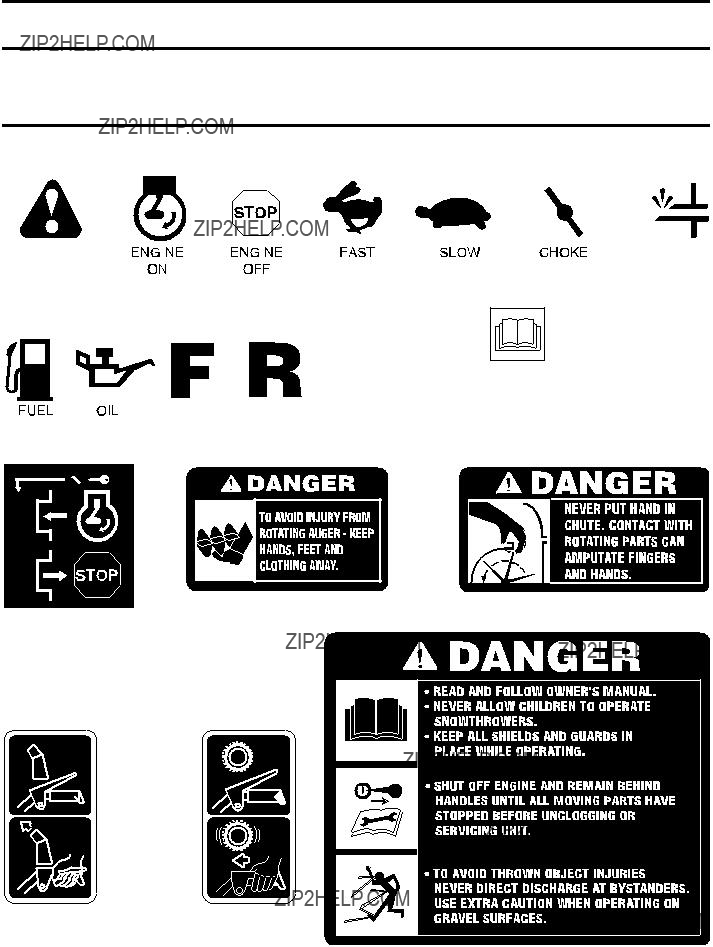
These symbols may appear on your snow thrower or in literature supplied with the product. Learn and understand their meaning.
OR WARNING
READ AND FOLLOW ALL SAFETY INFORMATION
AND INSTRUCTIONS BEFORE USE OF THIS PRODUCT.
FORWARD REVERSE KEEP THESE INSTRUCTIONS FOR FUTURE REFERENCE.
SPARK
PLUG
SAFETY
IGNITION
KEY
CHOKE
CON-
TROL
NOTE: ITEMS ABOVE
ARE SHOWN IN
THEIR TYPICAL
LOCATION ON THE
ENGINE. ACTUAL
LOCATION MAY VARY
WITH THE ENGINE
ON YOUR UNIT.
AUGERS
GASOLINE
FILLER
CAP
CHUTE
DEFLECTOR
OIL DRAIN
PLUG
FUEL SHUT-OFF VALVE
DISCHARGE
CHUTE
FIG. 10
TRACTION
DRIVE
CONTROL
LEVER
LH TURN
TRIGGER
LIGHT
HANDLE
KNOB
MUFFLER
TOOLBOX
DRIFT
CUTTER
SKID PLATE
MEETS A.N.S.I. SAFETY REQUIREMENTS
Our snow throwers conform to the standards of the American National Standards Institute.
Toolbox - to store spare shear bolts, locknuts & wrench.
Safety ignition key - must be inserted for the engine to start and run. Remove when snow thrower is not in use.
Electric start button - used for starting the engine.
Recoil (auxiliary) starter handle - used for starting the engine.
Primer - pumps additional fuel from the carburetor to the cylinder for use when starting a cold engine.
Choke Control - used for starting a cold engine.
Throttle/engine control - used to select either FAST or SLOW engine speed and to STOP the engine.
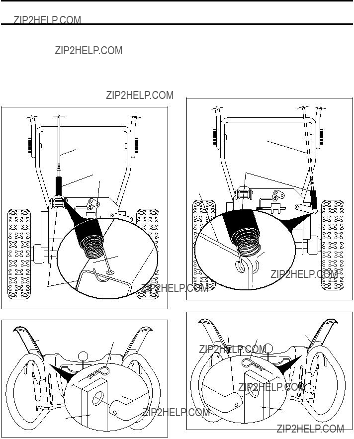
LH and RH turn triggers - used to steer the snow thrower.
Drive speed control lever - used to select forward or reverse motion and speed of snow thrower.
Traction drive control lever - used to engage power-pro- pelled forward or reverse motion of snow thrower.
Auger control lever - used to engage auger motion (throw snow).
Discharge chute control lever - used to change the di- rection the snow is thrown.
De???ector remote control lever - used to change the distance the snow is thrown.
Skid plate - used to adjust height of scraper bar from the ground.
9 Drift cutter - used to cut through deep snowdrifts.
TROUBLESHOOTING
See appropriate section in manual unless directed to a quali???ed service center.
LIMITED WARRANTY
The Manufacturer warrants to the original consumer purchaser that this product as manufactured is free from de- fects in materials and workmanship. For a period of two (2) years from date of purchase by the original consumer purchaser, we will repair or replace, at our option, without charge for parts or labor incurred in replacing parts, any part which we ??? nd to be defective due to materials or workmanship. This Warranty is subject to the following limita- tions and exclusions.
1.This warranty does not apply to the engine or components parts thereof. Please refer to the applicable manu- facturer's warranty on these items.
2.Transportation charges for the movement of any power equipment unit or attachment are the responsibility of the purchaser. Transportation charges for any parts submitted for replacement under this warranty must be paid by the purchaser unless such return is requested by Electrolux Home Products.
3.The Warranty period for any products used for rental or commercial purposes is limited to 90 days from the date of original purchase.
4.This Warranty applies only to products which have been properly assembled, adjusted, operated, and maintained in accordance with the instructions furnished. This Warranty does not apply to any product which has been subjected to alteration, misuse, abuse, improper assembly or installation, delivery damage, or to normal wear of the product.
5.Exclusions: Excluded from this Warranty are belts, shear pins, normal wear, normal adjustments, standard hardware and normal maintenance.
6.In the event you have a claim under this Warranty, you must return the product to an authorized service dealer. Should you have any unanswered questions concerning this Warranty, please contact:
giving the complete mfg. ID#, serial number and date of purchase of your product and the name and address of the authorized dealer from whom it was purchased.
THIS WARRANTY DOES NOT APPLY TO INCIDENTAL OR CONSEQUENTIAL DAMAGES AND ANY IMPLIED
WARRANTIES ARE LIMITED TO THE SAME TIME PERIODS STATED HEREIN FOR OUR EXPRESSED WAR- RANTIES. Some areas do not allow the limitation of consequential damages or limitations of how long an implied Warranty may last, so the above limitations or exclusions may not apply to you.This Warranty gives you speci??? c legal rights, and you may have other rights which vary from locale to locale.
This is a limited Warranty within the meaning of that term as de??? ned in the Magnuson-Moss Act of 1975.
 WARNING:


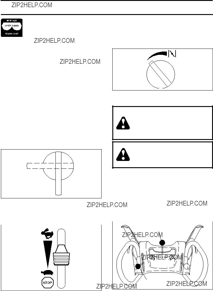


 safety glasses or eye shields while operating