R

Instruction Manual Manual de Instrucciones Manuel d???Instructions

PP446T

ENGLISH

For Occasional Use Only

WARNING:

Read and follow all Safety Rules and Operating Instructions before using this product. Failure to do so can result in serious injury.

ADVERTENCIA:

Lea el manual de instrucciones y siga todas las advertencias e instrucciones de seguridad. El no hacerlo puede resultar en le- siones graves.

AVERTISSEMENT:

Lire le manuel d???instructions et bien respecter tous les avertisse- ments et toutes les instructions de s??curit??. Tout d??faut de le faire pourrait entra??ner des blessures graves.

Electrolux Home Products, Inc.

104 Warren Road

Augusta, GA 30907

ESPA??OL

FRAN??AIS

IDENTIFICATION OF SYMBOLS

serious or even fatal injury.

Always wear appropriate ear protection, eye protection and head protection.

DANGER! Falling objects can cause severe head injury. Wear head protection when operating this unit. Do not stand beneath branch being cut.

SAFETY RULES

WARNING: Always disconnect spark plug wire and place wire where it cannot contact spark plug to prevent accidental starting when setting up, transporting, adjusting or making re- pairs except carburetor adjustments.

Because a pruner is a high-speed wood-cutting tool, special safety precautions must be ob- served to reduce the risk of accidents. Careless or improper use of this tool can cause serious or even fatal injury.

PLAN AHEAD

S Read this manual carefully until you completely understand and can follow all safety rules, precautions, and operating instructions before attempting to use the unit.

SRestrict the use of your pruner to adult users who understand and can follow safety rules, precautions, and operating instructions found on the unit and in this manual.

PRUNER SAFETY

S Wear protective gear. Always use steel-toed safety footwear with non-slip soles; snug-fitting clothing; heavy, long

pants, and long sleeves; heavy-duty, non-slip gloves; eye protection such as non-fogging, vented goggles or face screen; an approved safety hard hat; and sound barriers (ear plugs or mufflers) to protect your hearing. Regular users should have hearing checked regularly as engine noise can damage hearing. Secure hair above shoulder length. Secure or remove loose clothing and jewelry or clothing with loosely hanging ties, straps, tassels, etc.

SKeep all parts of your body away from the chain when the engine is running.

SKeep children, bystanders, and animals a minimum of 50 feet (15 meters) away from the work area. Do not allow other people or animals to be near when starting or operating the pruner.

HAZARD ZONE

50 feet

(15 meters)

DANGER: Do not

use near electrical wires or power lines.

Keep pruner at least 30 feet (10 meters) away from all power lines.

2

SDo not handle or operate a pruner when you are fatigued, ill, or upset, or if you have taken alcohol, drugs, or medication. You must be in good physical condition and mentally alert. If you have any condition that might be aggravated by strenuous work, check with doctor before operating a pruner.

SDo not operate the pruner with one hand. Serious injury to the operator, helpers, bystanders or any combination of these persons may result from one-handed operation. A pruner is intended for

two-handed use.

S Operate pruner only in a well-ventilated outdoor area.

SDo not operate pruner from a ladder or in a tree.

SDo not use a pruner to cut down trees or any portion of the tree trunk.

S Only use for pruning limbs or branches overhead not greater than 4 inches (10 cm) in diameter.

SNever stand under the limb you are pruning. Always position yourself out of the path of

falling debris.

SDo not cut small brush and saplings with the pruner. Slender matter may catch in the chain and be whipped toward you, pulling you off balance.

SMake sure the chain will not make contact with any object while starting the engine.

Never try to start the unit when the guide bar is in a cut.

SDo not put pressure on the pruner at the end of the cut. Applying pressure can cause you to lose control when the cut is completed.

S Do not run the unit at high speed when not pruning.

S If you strike or become entangled with a foreign object, stop the engine immediately

and check for damage. Have any damage repaired by an authorized service dealer before attempting further operations.

SDo not operate a pruner that is damaged, improperly adjusted, or not completely and securely assembled. Always replace bar

and chain immediately if it becomes damaged, broken or is otherwise removed.

SAlways stop the unit when work is delayed or when walking from one cutting location to another. Stop the engine before setting the

unit down.

S Carefully plan your pruning operation in advance. Do not start cutting until you have a clear work area, secure footing, and a planned retreat path.

S Use only in daylight or good artificial light.

SUse only for jobs explained in this manual (or manuals for optional attachments).

LINE TRIMMER SAFETY

DANGER: Never use blades with line trimmer attachment. Never use flailing de- vices with any attachment. This unit (when used with supplied line trimmer attachment) is

designed for line trimmer use only. Use of any other accessories with line trimmer attach- ment will increase the risk of injury.

WARNING: Trimmer line throws ob- jects violently. You and others can be blinded/in- jured. Wear eye and leg protection. Keep body parts clear of rotating line.

Eye Protection

Keep children, bystanders, and animals 50 feet (15 meters) away. Stop unit immediately if ap- proached.

S Dress properly. Always wear safety glasses or similar eye protection when operating, or performing maintenance, on your unit (safety glasses are available). Eye protection should be marked Z87.

SAlways wear face or dust mask if operation is dusty.

S Always wear heavy, long pants, long sleeves, boots, and gloves. Wearing safety leg guards is recommended.

S Always wear foot protection. Do not go barefoot or wear sandals. Stay clear of spinning line.

SSecure hair above shoulder length. Secure or remove loose clothing or clothing with

loosely hanging ties, straps, tassels, etc. They can be caught in moving parts.

SBeing fully covered also helps protect you from debris and pieces of toxic plants

thrown by spinning line.

SStay Alert. Do not operate this unit when you are tired, ill, upset or under the influence of alcohol, drugs, or medication. Watch what you are doing; use common

sense.

S Wear hearing protection.

S Never start or run inside a closed room or building. Breathing exhaust fumes can kill.

S Keep handles free of oil and fuel.

SAlways keep engine on the right hand side of your body.

S Hold the unit firmly with both hands.

S Keep trimmer head (or other optional attachment) below waist level and away

from all parts of your body. Do not raise engine above your waist.

S Keep all parts of your body away from muffler and spinning line (or other optional attachment). Keep engine below waist level. A hot muffler can cause serious burns.

S Keep firm footing and balance. Do not overreach or use from unstable surfaces

such as ladders, trees, steep slopes, rooftops, etc.

S Use only in daylight or good artificial light.

SUse only for jobs explained in this manual (or manuals for optional attachments).

3

MAINTAIN YOUR UNIT IN GOOD

WORKING ORDER

S Disconnect the spark plug before performing maintenance except carburetor adjustments.

S Look for and replace damaged or loose parts before each use. Look for and repair fuel leaks before use. Keep in good working condition.

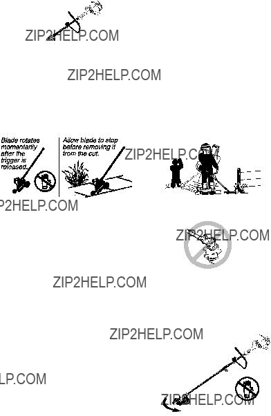
SMake certain the chain stops moving when the throttle trigger is released. For

correction, refer to CARBURETOR

ADJUSTMENTS.

S Replace trimmer head parts that are chipped, cracked, broken, or damaged in

any other way before using the unit. S Never modify your unit in any way.

SKeep the handles dry, clean, and free of oil or fuel mixture.

S Keep fuel and oil caps, screws, and fasteners securely tightened.

S Maintain unit according to recommended procedures. Keep cutting line at proper length.

S Use only 0.080??? (2 mm) diameter Poulan

PRO??? brand line. Never use wire, rope, string, etc.

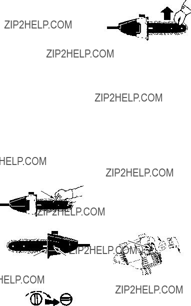
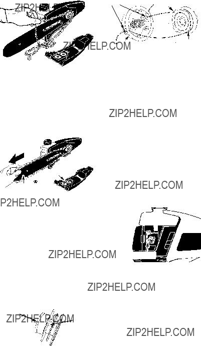
SInstall required shield properly before using the unit. Use only specified trimmer head;

make sure it is properly installed and securely fastened.

S Make sure unit is assembled correctly as shown in this manual.

S Make carburetor adjustments with lower end supported to prevent line from contacting any object.

SKeep others away when making carburetor adjustments.

S Use only recommended Poulan PRO??? accessories and replacement parts.

SHave all service performed by a qualified service dealer with the exception of the items listed in the maintenance section of this manual.

HANDLE FUEL WITH CAUTION

S Do not smoke while handling fuel or while operating the unit.

SEliminate all sources of sparks or flame in the areas where fuel is mixed or poured. There should be no smoking, open flames,

or work that could cause sparks. Allow engine to cool before refueling.

S Mix and pour fuel in an outdoor area on bare

ground; store fuel in a cool, dry, well ventilated place; and use an approved, marked container for all fuel purposes. Wipe up all fuel spills before starting engine.

S Move at least 10 feet (3 meters) from fueling site before starting engine.

S Turn the engine off and let unit cool in a non-combustible area, not on dry leaves, straw, paper, etc. Slowly remove fuel cap and refuel unit.

SStore the unit and fuel in an area where fuel vapors cannot reach sparks or open flames from water heaters, electric motors or switches, furnaces, etc.

S Stop engine and allow to cool before removing fuel cap.

S Always store gasoline in a container approved for flammable liquids.
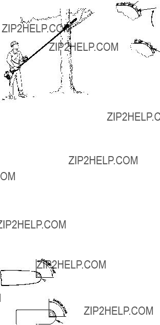
KICKBACK

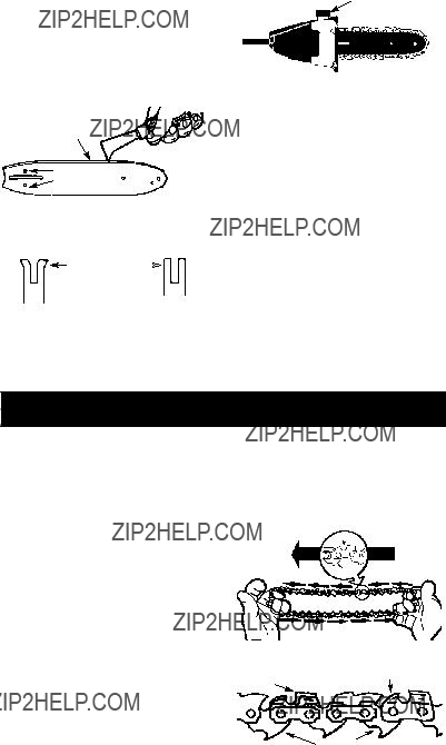
WARNING: Avoid kickback which can result in serious injury. Kickback is the backward, upward or sudden forward motion of the guide bar occurring when the chain near the upper tip of the guide bar contacts any object such as a log or branch, or when the wood closes in and pinches the chain in the cut. Contacting a foreign object in the wood can also result in loss of control.

S Rotational Kickback can occur when the moving chain contacts an object at the upper tip of the guide bar. This contact can cause the chain to dig into the object, which stops

the chain for an instant. The result is a lightning fast, reverse reaction which kicks the guide bar up and back toward the operator.

SPinch-Kickback can occur when the wood closes in and pinches the moving chain in the cut along the top of the guide bar and the chain is suddenly stopped. This sudden stopping of the chain results in a reversal of the chain force used to cut wood and causes the pruner to move in the opposite direction of the chain rotation. The pruner is

driven straight back toward the operator. S Pull-In can occur when the moving chain

contacts a foreign object in the wood in the cut along the bottom of the guide bar and the

chain is suddenly stopped. This sudden stopping pulls the pruner forward and away from the operator and could easily cause the operator to lose control of the pruner.

REDUCE THE CHANCE OF

KICKBACK

SRecognize that kickback can happen. With a basic understanding of kickback, you can reduce the element of surprise which contributes to accidents.

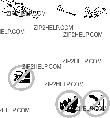
S Never let the moving chain contact any object at the tip of the guide bar.

S Keep the working area free from obstructions such as other trees, branches, rocks, stumps, etc. Eliminate or avoid any obstruction that your chain could hit while you are cutting. When cutting a branch, do not let the guide bar contact branch or other objects around it.

S Keep your chain sharp and properly

tensioned. A loose or dull chain can increase the chance of kickback occurring. Follow manufacturer???s chain sharpening and maintenance instructions. Check tension at regular intervals with the engine stopped, never with the engine running. Make sure the bar clamp nut is securely tightened after tensioning the chain.

S Begin and continue cutting at full speed. If the chain is moving at a slower speed, there is greater chance of kickback occurring.

S Cut one branch at a time.

S Use extreme caution when re-entering a previous cut.

SDo not attempt cuts starting with the tip of the bar (plunge cuts).

4

SWatch for shifting of wood or other forces that could close a cut and pinch or fall into chain.

SUse the Reduced--Kickback Guide Bar and Low--Kickback Chain specified for your unit.

MAINTAIN CONTROL

SKeep a good, firm grip on the pruner with both hands when the engine is running and don???t let go. A firm grip will help you reduce kickback and maintain control. Keep the fingers of your left hand encircling and your left thumb under the assist handle. Keep your right hand completely around the throttle handle whether your are right handed or left handed.

S Stand with your weight evenly balanced on both feet.

SStand slightly to the left side of the pruner to keep your body from being in a direct line with the cutting chain.

KICKBACK SAFETY FEATURES

The following features are included on your pruner to help reduce the hazard of kickback; however, such features will not totally elimi- nate this danger. As a pruner user, do not rely

only on safety devices. You must follow all safety precautions, instructions, and mainte- nance in this manual to help avoid kickback and other forces which can result in serious injury.

SReduced--Kickback Guide Bar, designed with a small radius tip which reduces the size of the kickback danger zone on the bar tip.

Reduced Kickback Symmetrical Guide Bar

Small Radius Tip

Symmetrical Guide Bar

Large Radius Tip

S Low--Kickback Chain, designed with a contoured depth gauge and guard link which deflect kickback force and allow wood to gradually ride into the cutter.

Contoured Depth Gauge

Not a Low--- Kickback Chain

SAFETY NOTICE: Exposure to vibrations through prolonged use of gasoline powered hand tools could cause blood vessel or nerve damage in the fingers, hands, and joints of people prone to circulation disorders or ab- normal swellings. Prolonged use in cold weather has been linked to blood vessel dam- age in otherwise healthy people. If symptoms

occur such as numbness, pain, loss of strength, change in skin color or texture, or loss of feeling in the fingers, hands, or joints, discontinue the use of this tool and seek med- ical attention. An anti--vibration system does not guarantee the avoidance of these prob- lems. Users who operate power tools on a continual and regular basis must monitor closely their physical condition and the condi-

tion of this tool.

SPECIAL NOTICE: This unit is equipped with a temperature limiting muffler and spark arresting screen which meets the require- ments of California Codes 4442 and 4443. All U.S. forest land and the states of California, Idaho, Maine, Minnesota, New Jersey, Ore- gon, and Washington require by law that many internal combustion engines be equipped with a spark arresting screen. If you

operate in a locale where such regulations ex- ist, you are legally responsible for maintaining the operating condition of these parts. Failure to do so is a violation of the law. For normal homeowner use, the muffler and spark arrest- ing screen will not require any service. After 50 hours of use, we recommend that your muffler be serviced or replaced by an autho- rized service dealer.

ADDITIONAL SAFETY RULES

FOR OPTIONAL ATTACHMENTS

WARNING: For each optional at- tachment used, read entire instruction manu- al before use and follow all warnings and in- structions in manual and on attachment.

WARNING: Ensure handlebar is

installed when using edger or brushcutter at- tachments. Attach handlebar above arrow on safety label on the upper shaft (engine end of unit). If your edger or brushcutter attachment does not include a handlebar, a handlebar ac- cessory kit (#530071451) is available from your authorized service dealer.

5

Handlebar

EDGER SAFETY

WARNING: Inspect the area to be edged before each use. Remove objects (rocks, broken glass, nails, wire, etc.) which

can be thrown by the blade or can wrap around the shaft.

SBlade rotates momentarily after the trigger is released. The blade can seriously cut you or others.

SAllow blade to stop before removing it from the cut.

SThrow away blades that are bent, warped, cracked, broken or damaged in any other

way. Replace parts that are cracked, chipped, or damaged before using the unit.

S Do not attempt to remove cut material nor hold material to be cut when the engine is running or when cutting blade is moving.

SAlways keep the wheel and depth adjusting skid in contact with the ground.

S Always push the unit slowly over the

ground. Stay alert for uneven sidewalks, holes in the terrain, large roots, etc.

SAlways use the handlebar when using edg- er attachment.

BLOWER/VACUUM SAFETY

WARNING: Inspect area before starting unit. Remove all debris and hard ob- jects such as rocks, glass, wire, etc. that can ricochet, be thrown, or otherwise cause injury or damage during operation.

S Do not set unit on any surface except a clean, hard area while engine is running.

Debris such as gravel, sand, dust, grass, etc., could be picked up by the air intake and thrown out through discharge opening, damaging unit, property, or causing serious injury to bystanders or operator.

S Never place objects inside the blower tubes, vacuum tubes or blower outlet. Al- ways direct the blowing debris away from people, animals, glass, and solid objects such as trees, automobiles, walls, etc. The

force of air can cause rocks, dirt, or sticks to be thrown or to ricochet which can hurt people or animals, break glass, or cause other damage.

S Never run unit without the proper equip- ment attached. When using your unit as a blower, always install blower tubes.

SCheck air intake opening, blower tubes or vacuum tubes frequently, always with en- gine stopped and spark plug disconnected. Keep vents and discharge tubes free of de-

bris which can accumulate and restrict proper air flow.

S Never place any object in air intake opening

as this could restrict proper air flow and cause damage to the unit.

SNever use for spreading chemicals, fertiliz- ers, or other substances which may contain toxic materials.

STo avoid spreading fire, do not use near leaf or brush fires, fireplaces, barbecue pits, ashtrays, etc.

BRUSHCUTTER SAFETY

DANGER: Blade can thrust violently

away from material it does not cut. Blade thrust can cause amputation of arms or legs.

WARNING: Do not use trimmer head as a fastening device for the blade.

WARNING: The blade continues to spin after the throttle is released or engine is turned off. The coasting blade can throw ob- jects or seriously cut you if accidentally

touched. Stop the blade by contacting the right hand side of the coasting blade with ma- terial already cut.

Stop coasting blade by contact with cut material.

WARNING: Inspect the area to be cut before each use. Remove objects (rocks, broken glass, nails, wire, etc.) which can be

thrown or become entangled in the blade or trimmer line.

S Throw away and replace blades that are bent, warped, cracked, broken or damaged in any other way.

6

SInstall required shield properly before using the unit. Use the metal shield for all metal blade use.

WARNING: Only use brushcutter at- tachments that provide a metal shield with proboscis nose.

Proboscis

nose

S Use only specified blade and make sure it is properly installed and securely fastened.

SCut from your left to your right. Cutting on the right side of the shield will throw debris

away from the operator.

SAlways use the handlebar and a properly adjusted shoulder strap with blade (see AS- SEMBLY instructions in brushcutter attach- ment instruction manual).

CULTIVATOR SAFETY

WARNING: Rotating tines can cause serious injury. Keep away from rotating tines.

Stop the engine and disconnect the spark plug before unclogging tines or making repairs.

terial when the blade is in motion. Make sure the switch is in the OFF position, the spark plug wire is disconnected, and the blade has stopped moving before removing jammed material from the cutting blade. Do not grab or hold the unit by the cutting blade.

WARNING: Inspect the area before starting the unit. Remove all debris and hard objects such as rocks, glass, wire, etc. that can ricochet, be thrown, or otherwise cause injury or damage during operation.

S Do not use a cutting blade that is bent, warped, cracked, broken or damaged in any other way. Have worn or damaged parts re- placed by your authorized service dealer.

S Always keep unit in front of your body.

Keep all parts of your body away from the cutting blade.

SKeep the cutting blade and air vents clear of debris.

SNOW THROWER SAFETY

WARNING: Keep hands and feet away from the rotor when starting or running the engine. Never attempt to clear the rotor with the engine/motor running. Stop engine

and disconnect spark plug before unclogging snow or debris from discharge chute or when adjusting vanes.

WARNING: Inspect the area to be cultivated before starting the unit. Remove all debris and hard and sharp objects such as rocks, vines, branches, rope, string, etc.

SAvoid heavy contact with solid objects that might stop the tines. If heavy contact oc- curs, stop the engine and inspect the unit

for damage.

S Never operate the cultivator without the tine

cover in place and properly secured.

S Keep the tines and guard clear of debris.

SAfter striking a foreign object, stop the engine, disconnect the spark plug and inspect the cul-

tivator for damage. Repair before restarting.

SDisconnect attachment from the drive en- gine before cleaning the tines with a hose and water to remove any build--up. Oil the tines to prevent rust.

S Always wear gloves when servicing or cleaning the tines. The tines become very sharp from use.

SDo not run unit at high speed unless culti- vating.

HEDGE TRIMMER SAFETY

DANGER: RISK OF CUT; KEEP HANDS AWAY FROM BLADE -- Blade moves momentarily after the trigger is re- leased. Do not attempt to clear away cut ma-

WARNING: Never lean over dis- charge chute. Rocks or debris could be

thrown into the eyes and face and cause seri- ous injury or blindness.

WARNING: Inspect the area where the unit is to be used. Remove objects that could be thrown or damage the unit. Some

objects may be hidden by fallen snow -- be alert for the possibility.

SDirect material discharge away from glass enclosures, automobiles, etc.

S Do not run engine at high speed while not removing snow.

SBe attentive when using the snowthrower, and stay alert for holes in the terrain and other hidden hazards.

SMake sure the rotor will spin freely before attaching the snowthrower to the power- head.

7

SIf the rotor will not rotate freely due to frozen ice, thaw the unit before thoroughly before

attempting to operate under power. S Keep the rotor clear of debris.

SDo not throw snow near other people. The snow thrower could propel small objects at high speed causing injury.

SAfter striking a foreign object, stop the en- gine, disconnect spark plug and inspect the snowthrower for damage and repair if nec- essary before restarting unit.

S Never operate the snowthrower near glass enclosures, automobiles and trucks.

SNever attempt to use the snowthrower on a roof.

SNever operate the snowthrower near win- dow wells, dropoffs, etc.

SNever discharge snow onto public roads or near moving traffic.

SClear snow from slopes by going up and down; never across. Use caution when changing directions. Never clear snow

from steep slopes.

S Let snowthrower run for a few minutes after clearing snow so moving parts do not freeze.

S Look behind and use care when backing up. Exercise caution to avoid slipping or fal- ling, especially when operating in reverse.

S Know how to stop quickly.

ASSEMBLY

WARNING: If received assembled, repeat all steps to ensure your unit is properly assembled and all fasteners are secure.

Examine parts for damage. Do not use dam- aged parts.

NOTE: If you need assistance or find parts missing or damaged, call 1-800-554-6723.

It is normal for the fuel filter to rattle in the empty fuel tank.

Finding fuel or oil residue on muffler is normal due to carburetor adjustments and testing done by the manufacturer.

TOOLS REQUIRED

S Hex wrench (provided)

INSTALLING PRUNER OR LINE

TRIMMER ATTACHMENTS CAUTION: When removing or installing at- tachments, place the unit on a flat surface for stability.

1.Loosen the coupler by turning the knob counterclockwise.

Coupler

LOOSEN

WARNING: Make sure the locking/ release button is locked in the primary hole and the knob is securely tightened before op- erating the unit. All attachments are designed

to be used in the primary hole.

For optional attachments, see the AS- SEMBLY section of the applicable attach- ment instruction manual.

SHOULDER STRAP ASSEMBLY

WARNING: Proper shoulder strap adjustments must be made with the engine completely stopped before using unit.

Shipping protector

TIGHTEN

Knob

NOTE: A one-half twist is built in the shoul- der strap to allow the strap to rest flat on the shoulder.

2.Remove shipping protector from coupler.

3.Remove the shaft cap from the attach- ment (if present).

4.Position locking/release button of attach- ment into guide recess of coupler.

5.Push the attachment into the coupler until the locking/release button snaps into the primary hole.

6.Before using the unit, tighten the knob se- curely by turning clockwise.

NOTE: It may be necessary to relocate the

shoulder strap clamp on the shaft for proper balancing of unit.

TO RELOCATE SHOULDER STRAP

CLAMP:

1.Loosen and remove both clamp screws.

2.Place the upper shoulder strap clamp over the upper shaft.

8

3.Position the lower shoulder strap clamp under the upper shaft and align the upper and lower clamp screw holes.

Upper Shoulder

Strap Clamp

POWERHEAD

END

4.Insert two screws into the screw holes.

5.Secure shoulder strap clamp by tighten- ing screws with a hex wrench.

ADJUSTING THE ASSIST HANDLE

WARNING: When adjusting the as- sist handle, be sure it remains between the

coupler) on the safety label to ensure proper

1.Loosen wing nut on handle.

2.Rotate the handle on the shaft to an up- right position; retighten wing nut.

ATTACHING SHIELD (FOR LINE

TRIMMER ATTACHMENT)

WARNING: The shield must be prop- erly installed. The shield provides partial protec- tion from the risk of thrown objects to the opera- tor and others and is equipped with a line limiter blade which cuts excess line to the proper length. The line limiter blade (on underside of shield) is sharp and can cut you. For proper orientation of shield, see KNOW YOUR TRIM- MER illustration in OPERATION section.

1.Remove wing nut from shield.

2.Insert bracket into slot as shown.

3.Pivot shield until bolt passes through hole in bracket.

4.Securely tighten wing nut onto bolt.

Slot

Shield

Bracket

balancing of unit. When adjusting the assist handle or handlebar during use of optional at- tachments, it must be repositioned between

the throttle trigger and the upper arrow (closest to engine) on the safety label.
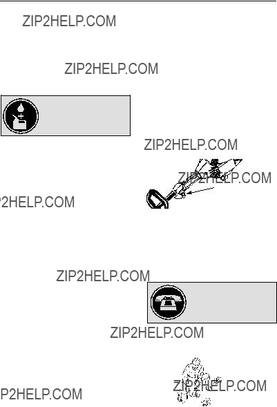
Line Limiter Blade

Wing

Nut

OPERATION

KNOW YOUR PRUNER

READ THIS INSTRUCTION MANUAL AND SAFETY RULES BEFORE OPERATING YOUR UNIT. Compare the illustrations with your unit to familiarize yourself with the location of the various controls

and adjustments. Save this manual for future reference.

ON/OFF SWITCH

The ON/OFF switch is located on the trigger handle and is used to stop the engine. Move the switch to the OFF position to stop the engine.

PRIMER BULB

The PRIMER BULB removes air from the car- buretor and fuel lines and fills them with fuel. This allows you to start the engine with fewer pulls on the starter rope. Activate the primer bulb by pressing it and allowing it to return to its origi-

nal form.

9

CHOKE

The CHOKE helps to supply fuel to the engine to aid in cold starting. Activate the choke by moving the choke lever to the FULL CHOKE position. After the engine attempts to start, move the choke lever to the HALF CHOKE position.

Once engine has started, move the choke lever to the OFF CHOKE position.

COUPLER

The COUPLER enables optional attach- ments to be installed on the unit.

CHAIN TENSION

It is normal for a new chain to stretch during first 15 minutes of operation. You should check your chain tension frequently. See CHAIN TENSION in the SERVICE AND AD-

JUSTMENTS section.

BEFORE STARTING ENGINE

WARNING: Be sure to read the fuel information in the safety rules before you be-

gin. If you do not understand the safety rules, do not attempt to fuel your unit. Call 1-800-554-6723.

FUELING ENGINE

WARNING: Remove fuel cap slowly when refueling.

HELPFUL TIP

To obtain the correct oil mix ratio, pour 3.2 ounces of 2-cycle synthetic oil into one gallon of fresh gas.

This engine is certified to operate on unleaded gasoline. Before operation, gasoline must be mixed with a good quality synthetic 2-cycle air-cooled engine oil

designed to be mixed at a ratio of 40:1. Poulan/Weed Eater brand synthetic oil is recommended. Mix gasoline and oil at a ratio of 40:1. A 40:1 ratio is obtained by mixing 3.2 ounces (95 ml) of oil with 1 gallon (4 liters) of unleaded gasoline. DO NOT USE automotive oil or marine oil. These oils will cause engine damage. When mixing fuel, follow instructions printed on container. Once oil is added to gasoline, shake container momentarily to assure that the fuel is thoroughly mixed. Always read and follow the safety rules relating to fuel before fueling your unit.

BAR AND CHAIN LUBRICATION

The bar and chain require lubrication. The chain oiler provides continuous lubrication to the chain and guide bar. Be sure to fill the bar oil tank when you fill the fuel tank (Capacity = 4.6 fl. oz.). Lack of oil will quickly ruin the bar and chain. Too little oil will cause overheating shown by

smoke coming from the chain and/or discolor- ation of the bar. The oil output is automatically metered during operation. Always fill the bar oil tank when you fill the fuel tank.

Genuine PoulanR or Poulan PROR bar and chain oil is recommended to protect your unit against excessive wear from heat and fric- tion. PoulanR or Poulan PROR oil resists high temperature thinning. If PoulanR or Pou- lan PROR bar and chain oil is not available,

use a good grade SAE 30 oil.

S Never use waste oil for bar and chain lubrication.

S Always stop the engine before removing the oil cap.

IMPORTANT

Experience indicates that alcohol blended fuels (called gasohol or using ethanol or methanol) can attract moisture which leads to separation and formation of acids during stor- age. Acidic gas can damage the fuel system of an engine while in storage. To avoid engine problems, empty the fuel system before stor- age for 30 days or longer. Drain the gas tank, start the engine and let it run until the fuel lines and carburetor are empty. Use fresh fuel next season. Never use engine or carburetor cleaner products in the fuel tank or permanent damage may occur.

See the STORAGE section for additional in- formation.

HOW TO STOP YOUR UNIT

S To stop the engine, move the ON/OFF switch to the OFF position.

SIf engine does not stop, move choke lever to the FULL CHOKE position.

ON/OFF Switch

HOW TO START YOUR UNIT

WARNING: Make sure the chain will not make contact with any object while start- ing the engine. Never try to start the unit when the guide bar is in a cut. Avoid any contact with the muffler. A hot muffler can cause seri- ous burns.

HELPFUL TIP

If your engine still does not start after following these instructions, please call 1-800-554-6723.

STARTING A COLD ENGINE (or a warm engine after running out of

fuel)

Starting Position

10

Starter Handle

Choke

Lever

Primer Bulb

Muffler

1.Set unit on a flat surface.

2.Move ON/OFF switch to the ON position.

3.Slowly press the primer bulb 6 times.

4.Move choke lever to FULL CHOKE by aligning lever with position shown on de- cal (see illustration below).

Choke position

decal

5.Squeeze the throttle trigger fully and hold through all remaining steps.

6.Pull starter rope handle sharply until en- gine sounds as if it is trying to start, but do not pull rope more than 6 times.

7.As soon as engine sounds as if it is trying to start, move choke lever to HALF CHOKE by aligning lever with position shown on decal (see illustration below).

Choke position decal

8.Pull starter rope sharply until engine runs, but no more than 6 pulls. If the engine doesn???t start after 6 pulls (at the HALF CHOKE position), move the choke lever to the FULL CHOKE position and press the primer bulb 6 times. Squeeze and hold the throttle trigger and pull the starter rope 2 more times. Move the choke lever to the HALF CHOKE position and pull the starter rope until the engine runs, but no more than 6 pulls. If the engine doesn???t start, repeat procedure 2 additional times. NOTE: If

engine still doesn???t start, it is probably flooded. Proceed to STARTING A

FLOODED ENGINE.

9.Once the engine starts, allow it to run 10 se- conds, then move the choke lever to OFF CHOKE by aligning lever with position shown on decal (see illustration below). Al- low the unit to run for 30 more seconds at OFF CHOKE before releasing the throttle trigger.

NOTE: If engine dies with the choke lever

in the OFF CHOKE position, move the choke lever to the HALF CHOKE position and pull the rope until engine runs, but no more than 6 pulls.

Choke position decal

STARTING A WARM ENGINE

1.Move ON/OFF switch to the ON position.

2.Move the choke lever to the HALF CHOKE position.

3.Squeeze and hold the throttle trigger. Keep throttle trigger fully squeezed until the engine runs smoothly.

4.Pull starter rope sharply until engine runs, but no more than 5 pulls.

5.Allow engine to run 15 seconds, then move the choke lever to the OFF CHOKE position.

NOTE: If engine has not started, pull starter rope 5 more pulls. If engine still does not run, it is probably flooded.

STARTING A FLOODED ENGINE

Flooded engines can be started by placing the choke lever in the OFF CHOKE position; then, pull the rope to clear the engine of ex-

cess fuel. This could require pulling the starter handle many times depending on how badly the unit is flooded.

If the unit still doesn???t start, refer to TROUBLESHOOTING TABLE or call 1-800-554-6723.

OPERATING THE COUPLER

This model is equipped with a coupler which enables optional attachments to be installed. The optional attachments are:

MODEL:

Edger . . . . . . . . . . . . . . . . . . . . . . . PP1000E Cultivator . . . . . . . . . . . . . . . . . . . . PP2000T Blower . . . . . . . . . . . . . . . . . . . . . . PP3000B Brushcutter . . . . . . . . . . . . . . . . . . PP4000C

WARNING: Always stop unit and dis- connect spark plug before removing or instal- ling attachments.

REMOVING PRUNER ATTACH-

MENT, LINE TRIMMER ATTACH-

MENT, OR OTHER OPTIONAL AT-

TACHMENTS

CAUTION: When removing or installing at- tachments, place the unit on a flat surface for stability.

1.Loosen the coupler by turning the knob counterclockwise.

11

Upper Shaft

Coupler

OPERATING INSTRUCTIONS FOR

PRUNER ATTACHMENT

OPERATING POSITION

Lower

Attachment

LOOSEN

ALWAYS WEAR:

Head

Protection Eye

Protection

TIGHTEN Knob

2. Press and hold the locking/release button.

Locking/Release Button

3.While securely holding the engine and upper shaft, pull the attachment straight out of the coupler.

INSTALLING OPTIONAL ATTACH-

MENTS

1.Remove the shaft cap from the attach- ment (if present).

2.Position locking/release button of attach- ment into guide recess of coupler.

3.Push the attachment into the coupler until the locking/release button snaps into the primary hole.

4.Before using the unit, tighten the knob se- curely by turning clockwise.

Coupler Primary Hole

Guide Recess

Upper Locking/ Attachment

Shaft Release

Button

WARNING: Make sure the locking/ release button is locked in the primary hole and the knob is securely tightened before op- erating the unit.

INSTALLING ATTACHMENT

HANGER

An attachment hanger is provided for storage when attachment is not in use.

To install hanger on attachment:

1.Remove the shaft cap from the attach- ment (if present) and discard.

2.Press and hold the locking/release button.

3.Push hanger onto the attachment until the locking/release button snaps into the hole.

OPERATING INSTRUCTIONS

It is recommended that the engine not be operated for longer than 1 minute at full throttle.

Long Pants

Heavy Shoes

DANGER: Do not extend arms above shoulders while pruning. Do not stand be-

neath branch being cut.

WARNING: Always wear head, eye, hearing, foot and body protection to reduce the risk of injury when operating this unit.

When operating unit, clip shoulder strap onto clamp, stand as shown and check for the fol- lowing:

S Extend your left arm and hold assist handle with your left hand.

SHold throttle grip with your right hand with finger on throttle trigger.

S Keep engine end below waist level.

SKeep shoulder strap pad centered on your left shoulder and danger sign centered on

your back.

S Maintain full weight of tool on your left shoulder.

Always release the throttle trigger and allow the engine to return to idle speed when not pruning. To stop engine:

S Release the throttle trigger.

SMove the ON/OFF switch to the OFF posi- tion.

PRUNING

WARNING: Be alert for and guard against kickback. Do not allow the moving chain to contact any other branches or ob- jects at the nose of the guide bar when prun-

ing. Allowing such contact can result in seri- ous injury.

IMPORTANT POINTS

S Work slowly, keeping both hands firmly gripped on the pruner. Maintain secure footing and balance.

SPlan cut carefully. Check direction branch will fall.

S Watch out for springpoles. Springpoles are small size limbs which can catch the chain and whip toward you or pull you off balance. Use extreme caution when cutting small size limbs or slender material.

12

SWatch out for branches immediately behind the branch being pruned. If the chain hits the

rear branch, damage to the unit may occur. S Be alert for springback. Watch out for branches that are bent or under pressure. Avoid being struck by the branch or the pruner when the tension in the wood fibers

is released.

SKeep a clear work area. Frequently clear branches out of the way to avoid tripping over them.

S Long branches should be removed in several pieces.

PRUNING TECHNIQUE

When ready to cut, accelerate to full throttle

and apply a light cutting pressure. DO NOT use back and forth sawing action.

Second cut

Third cut

Collar

First cut

Pruning technique

1.Make the first cut 6 inches (15 cm) from the tree trunk on the bottom of the limb. Use top of guide bar to make this cut. Cut 1/3 through the diameter of the limb.

NOTE: When making the second and third

cuts, rest the foot of the pruner against the tree limb that is being cut to prevent whipping of the branch.

Foot

2.Next, move 2 -- 4 inches (5 -- 10 cm) far- ther out on the limb and make a second cut all the way through the limb.

3.Then, make a final cut leaving a 1 -- 2 inch (2.5 -- 5 cm) collar from the trunk of the tree to avoid damage to the tree.

OPERATING INSTRUCTIONS FOR

TRIMMER ATTACHMENT

OPERATING POSITION

ALWAYS WEAR:

Eye Protection

Long Pants

Heavy Shoes

Cut from your right to your left.

WARNING: Always wear eye protec- tion. Never lean over the trimmer head. Rocks or debris can ricochet or be thrown into

eyes and face and cause blindness or other serious injury.

Do not run the engine at a higher speed than necessary. The cutting line will cut efficiently when the engine is run at less than full throttle. At lower speeds, there is less engine noise

and vibration. The cutting line will last longer and will be less likely to ???weld??? onto the spool. Always release the throttle trigger and allow the engine to return to idle speed when not cutting.

To stop engine:

S Release the throttle trigger.

S Move the ON/OFF switch to the OFF position.

TRIMMER LINE ADVANCE

The trimmer line will advance approximately 2 inches (5 cm) each time the bottom of the trimmer head is tapped on the ground with the engine running at full throttle.

The most efficient line length is the maximum length allowed by the line limiter.

Always keep the shield in place when the tool is being operated.

To advance line:

S Operate the engine at full throttle.

S Hold the trimmer head parallel to and above

the grassy area.

S Tap the bottom of the trimmer head lightly on the ground one time. Approximately 2 inches (5 cm) of line will be advanced with each tap.

Always tap the trimmer head on a grassy area. Tapping on surfaces such as concrete or asphalt can cause excessive wear to the trimmer head.

If the line is worn down to 2 inches (5 cm) or less, more than one tap will be required to ob-

tain the most efficient line length.

WARNING: Use only 0.080??? (2 mm) diameter line. Other sizes of line will not ad- vance properly and can cause serious injury. Do not use other materials such as wire, string, rope, etc. Wire can break off during cutting and become a dangerous missile that can cause serious injury.

13

CUTTING METHODS

WARNING: Use minimum speed and do not crowd the line when cutting around hard objects (rock, gravel, fence posts, etc.), which can damage the trimmer head, become

entangled in the line, or be thrown causing a serious hazard.

SThe tip of the line does the cutting. You will achieve the best performance and minimum line wear by not crowding the line into the cutting area. The right and wrong

ways are shown below.

RightWrong

S The line will easily remove grass and weeds from around walls, fences, trees and flower beds, but it also can cut the tender bark of trees or shrubs and scar fences.

SFor trimming or scalping, use less than full throttle to increase line life and decrease head wear, especially:

S During light duty cutting.

S Near objects around which the line can

wrap such as small posts, trees or fence wire.

S For mowing or sweeping, use full throttle for a good clean job.

TRIMMING -- Hold the bottom of the trimmer

head about 3 inches (8 cm) above the ground and at an angle. Allow only the tip of the line to make contact. Do not force trimmer line into work area.

Trimming

3 inches (8 cm) above ground

SCALPING -- The scalping technique re- moves unwanted vegetation down to the ground. Hold the bottom of the trimmer head about 3 inches (8 cm) above the ground and at an angle. Allow the tip of the line to strike the ground around trees, posts, monuments, etc. This technique increases line

wear.

Scalping

MOWING -- Your trimmer is ideal for mowing in places conventional lawn mowers cannot reach. In the mowing position, keep the line parallel to the ground. Avoid pressing the

head into the ground as this can scalp the ground and damage the tool.

Mowing

SWEEPING -- The fanning action of the rotat- ing line can be used for a quick and easy clean up. Keep the line parallel to and above the surfaces being swept and move the tool fromsideto side.

Sweeping

MAINTENANCE

WARNING: Disconnect the spark plug before performing maintenance except for carburetor adjustments.

HELPFUL TIP

IMPORTANT: Have all

repairs other than the rec- ommended maintenance

described in the instruction manual performed by an authorized service dealer.

If any dealer other than an authorized

service dealer performs work on the product, Electrolux Home Products,

Inc., may not pay for repairs under war- ranty. It is your responsibility to maintain and perform general maintenance.

14

CHECK FOR LOOSE

FASTENERS AND PARTS

S Spark Plug Boot

S Air Filter

S Housing Screws

S Assist Handle Screw

S Debris Shield

CHECK FOR DAMAGED OR

WORN PARTS

Contact an authorized service dealer for re- placement of damaged or worn parts.

SON/OFF switch -- Ensure ON/OFF switch functions properly by moving the switch to the OFF position. Make sure engine stops;

then restart engine and continue.

S Fuel tank -- Discontinue use of unit if fuel tank shows signs of damage or leaks.

S Oil tank -- Discontinue use of unit if oil tank shows signs of damage or leaks.

SDebris shield -- Discontinue use of unit if de- bris shield is damaged.

INSPECT AND CLEAN UNIT AND LA-

BELS

S After each use, inspect complete unit for loose or damaged parts. Clean the unit and labels using a damp cloth with a mild deter- gent.

S Wipe off unit with a clean dry cloth.

CHECK CHAIN TENSION

WARNING: Wear protective gloves

when handling chain. The chain is sharp and can cut you even when it is not moving. Make chain adjustments with lower end supported.

Chain tension is very important. Chains stretch during use. This is especially true dur- ing the first few times you use your pruner. Al- ways check chain tension each time you use and refuel your unit.

1.Use the screwdriver end of the chain ad- justment tool (bar tool) to move chain around guide bar to ensure kinks do not exist. The chain should rotate freely.

Chain Adjustment Tool

Guide

Bar

2.Loosen bar clamp nut until it is finger tight against the bar clamp.

3.Turn adjusting screw clockwise until chain solidly contacts bottom of guide bar rail. Then, turn adjusting screw an addi- tional 1/4 turn.

Adjusting Screw -- 1/4 Turn

4.Using bar tool, roll chain around guide bar to ensure all links are in bar groove.

5.Lift up tip of guide bar to check for sag. Release tip of guide bar, then turn adjust- ing screw 1/4 turn clockwise. Repeat until sag does not exist.

6.While lifting tip of guide bar, tighten bar clamp nut securely with the bar tool.

7.Use the screwdriver end of the bar tool to move chain around guide bar.

8.If chain does not rotate, it is too tight. Slightly loosen bar clamp nut and loosen chain by turning the adjusting screw 1/4 turn counterclockwise. Retighten bar clamp nut.

9.If chain is too loose, it will sag below the guide bar and needs to be tightened fol- lowing above procedure.

WARNING: DO NOT operate the pruner if the chain is loose. If the pruner is oper- ated with a loose chain, the chain could jump off the guide bar and result in serious injury.

CHECK CHAIN SHARPNESS

A sharp chain makes wood chips. A dull chain

makes a sawdust powder and cuts slowly. See CHAIN SHARPENING in the SERVICE AND ADJUSTMENTS section.

CLEAN AIR FILTER

A dirty air filter decreases engine perform- ance and increases fuel consumption and harmful emissions. Always clean after every 5 hours of operation.

1. Clean the cover and the area around it to keep dirt from falling into the carburetor chamber when the cover is removed.

2. Remove parts by pressing button to re- lease air filter cover.

NOTE: To avoid creating a fire hazard or producing harmful evaporative emissions, do not clean filter in gasoline or other flammable solvent.

3.Wash the filter in soap and water.

4.Allow filter to dry.

5.Replace parts.

Air Filter

Cover

BAR MAINTENANCE

If your pruner cuts to one side, has to be forced through the cut, or been run with an im- proper amount of bar lubrication it may be necessary to service your bar. A worn bar will damage your chain and make cutting difficult.

15

After each use, ensure ON/OFF switch is in the OFF position, then clean all sawdust from the guide bar and sprocket hole.

To maintain guide bar:

SMove ON/OFF switch to the OFF position and disconnect spark plug.

S Loosen and remove bar clamp nut and

chain brake. Remove bar and chain from pruner.

S Clean the oil holes and bar groove after each 5 hours of operation.

Remove Sawdust From

Guide Bar Groove

Oil Holes

S Burring of guide bar rails is a normal process of rail wear. Remove these burrs with a flat file.

SWhen rail top is uneven, use a flat file to restore square edges and sides.

File Rail Edges

and Sides

Square

Replace guide bar when the groove is worn, the guide bar is bent or cracked, or when excess heating or burring of the rails occurs. If replacement is necessary, use only the guide bar specified for your pruner in the repair

parts list.

LUBRICATION

Bar Oil

Fill Cap

SSee GUIDE BAR AND CHAIN OIL under the OPERATION section.

MUFFLER AND SPARK ARREST-

ING SCREEN

WARNING: The muffler on this prod-

uct contains chemicals known to the State of California to cause cancer.

As your unit is used, carbon deposits build up on the muffler and spark arresting screen. For normal homeowner use, however, the muffler and spark arresting screen will not re-

quire any service. After 50 hours of use, we recommend that your muffler be serviced or replaced by your authorized service dealer.

REPLACE SPARK PLUG

Replace the spark plug each year to ensure the engine starts easier and runs better. Set spark plug gap at 0.025 inch (0.6 mm). Igni- tion timing is fixed and nonadjustable.

1.Twist, then pull off spark plug boot.

2.Remove spark plug from cylinder and discard.

3.Replace with Champion RCJ-6Y spark plug and tighten securely with a 3/4 inch (19 mm) socket wrench.

4.Reinstall the spark plug boot.

SERVICE AND ADJUSTMENTS

WARNING: Disconnect the spark plug before performing maintenance, service, or adjustments except for carburetor adjustments.

CHAIN SHARPENING

Chain sharpening is a complicated task that requires special tools. We recommended you refer chain sharpening to a professional chain sharpener.

CHAIN REPLACEMENT

WARNING: Wear protective gloves when handling chain. The chain is sharp and can cut you even when it is not moving.

It is normal for a new chain to stretch during the first 15 minutes of operation. You should re- check your chain tension frequently and adjust the chain tension as required. See CHAIN TEN- SION section.

Replace the old chain when it becomes worn or damaged. Use only the Low-Kickback replace-

ment chain specified in the repair parts list.

TO REPLACE CHAIN:

1.Move ON/OFF switch to the OFF position and disconnect spark plug.

2.Remove bar clamp nut.

3.Remove bar clamp.

4.Turn adjusting screw by hand counter- clockwise until adjusting pin just touches the stop.

5.Slide guide bar behind sprocket until guide bar stops against sprocket.

6.Remove the old chain.

7.Carefully remove new chain from pack- age. Hold chain with the drive links as

shown.

Cutter

Tip of

Bar

Drivelink

CUTTERS MUST FACE IN

DIRECTION OF ROTATION

Drive Links

16

8.Place chain over sprocket, fitting the drive links in the sprocket.

9.Fit bottom of drive links between the teeth in the sprocket in the nose of the guide bar.

10.Fit chain drive links into bar groove.

11.Pull guide bar forward until chain is snug in guide bar groove. Ensure all drive links are in the bar groove.

12.Now, install bar clamp making sure the adjusting pin is positioned in the lower hole in the guide bar.

Lower

Hole

Adjusting Pin

Guide Bar

13.Install bar clamp nut and finger tighten only. Do not tighten any further at this point. Proceed to the CHAIN ADJUST- MENT section.

CHAIN ADJUSTMENT

See CHECK CHAIN TENSION in MAINTE- NANCE section.

REPLACING THE LINE

1.Remove spool by firmly pulling on tap button.

2.Clean entire surface of hub and spool.

3.Replace with a pre-wound spool, or cut two lengths of 12-1/2 feet of 0.080??? (2 mm) di- ameter Poulan PROr brand line.

WARNING: Never use wire, rope, string, etc., which can break off and become a dangerous missile.

4.Insert ends of the lines about 1/2 inch (1 cm) into the small holes on the inside of spool.

Spool

Small

Holes

5.Wind the line evenly and tightly onto the spool. Wind in the direction of the arrows found on the spool.

6.Push the lines into the notches, leaving 3 to 5 inches (7 -- 12 cm) unwound.

7.Insert the lines into the the exit holes in the hub as shown in the illustration.

8.Align the notches with the line exit holes.

9.Push spool into hub until it snaps into place.

10.Pull the lines extending outside of the hub to release the lines from the notches.

CARBURETOR ADJUSTMENT

WARNING: Keep others away when making idle speed adjustments. The chain will be moving during most of this procedure. Wear your protective equipment and observe all safety precautions. After making adjust- ments, the chain must not move at idle speed. The carburetor has been carefully set at the factory. Adjustment to the idle speed may be necessary if you notice any of the following

conditions:

SEngine will not idle when the throttle is re- leased.

S The chain moves at idle.

Make adjustments with the unit supported so the pruner is off the ground and the chain will not make contact with any object. Hold the unit by hand while running and making adjust- ments. Keep all parts of your body away from the chain and muffler.

Idle Speed Screw

IDLE SPEED ADJUSTMENT

Allow engine to idle. Adjust idle speed until en- gine runs without chain moving (idle too fast) or stalling (idle speed too slow).

S Turn idle speed screw clockwise to in- crease engine speed if engine stalls or dies.

S Turn idle speed screw counterclockwise to decrease engine speed if chain moves at idle.

WARNING: Recheck the idle speed

after each adjustment. The chain must not move at idle speed to avoid serious injury to the operator or others.

If you require further assistance or are unsure about performing this procedure, contact your authorized service dealer or call 1--800--554--6723.

17

STORAGE

WARNING: Perform the following steps after each use:

SAllow engine to cool before storing or trans- porting.

SStore unit and fuel in a well ventilated area where fuel vapors cannot reach sparks or open flames from water heaters, electric

motors or switches, furnaces, etc.

SStore unit with all guards in place. Position unit so that any sharp object cannot acci-

dentally cause injury.

SStore unit and fuel well out of the reach of children.

SEASONAL STORAGE

Prepare unit for storage at end of season or if it will not be used for 30 days or more.

If your unit is to be stored for a period of time: S Clean the entire unit before lengthy

storage.

S Store in a clean dry area.

S Lightly oil external metal surfaces.

FUEL SYSTEM

Under FUELING ENGINE in the OPERA-

TION section of this manual, see message la- beled IMPORTANT regarding the use of ga- sohol in your engine.

Fuel stabilizer is an acceptable alternative in minimizing the formation of fuel gum deposits during storage. Add stabilizer to the gasoline in the fuel tank or fuel storage container. Fol- low the mix instructions found on stabilizer container. Run engine at least 5 minutes after adding stabilizer.

HELPFUL TIP

During storage of your gas/

oil mixture, the oil will sepa- rate from the gas.

We recommend that you shake the gas can weekly to insure proper blending of the gas and oil.

ENGINE

SRemove spark plug and pour 1 teaspoon of 40:1, 2-cycle engine oil (air cooled) through

the spark plug opening. Slowly pull the starter rope 8 to 10 times to distribute oil.

S Replace spark plug with new one of recom- mended type and heat range.

S Clean air filter.

S Check entire unit for loose screws, nuts, and bolts. Replace any damaged, broken, or worn parts.

SAt the beginning of the next season, use only fresh fuel having the proper gasoline to oil ratio.

OTHER

SDo not store gasoline from one season to another.

S Replace your gasoline can if it starts to rust.

18

TROUBLESHOOTING TABLE

WARNING: Always stop unit and disconnect spark plug before performing all of the recommended remedies below except remedies that require operation of the unit.

19

LIMITED WARRANTY

ELECTROLUX HOME PRODUCTS, INC., warrants to the original purchaser that each new Poulan PROr brand gasoline tool or at- tachment is free from defects in material and workmanship and agrees to repair or replace under this warranty any defective gasoline product or attachment as follows from the

original date of purchase.

2 YEARS -- Parts and Labor, when used for household purposes.

90 DAYS -- Parts and Labor, when used for commercial, professional, or income produc- ing purposes.

30 DAYS -- Parts and Labor, if used for rental purposes.

This warranty is not transferable and does not cover damage or liability caused by improper

handling, improper maintenance, or the use of accessories and/or attachments not spe- cifically recommended by ELECTROLUX HOME PRODUCTS, INC., for this tool. Addi-

tionally, this warranty does not cover tune- ups, spark plugs, filters, cutting line, or rotat- ing head parts that will wear and require replacement with reasonable use during the warranty period. This warranty does not cov- er predelivery setup or normal adjustments explained in the instruction manual.

THIS WARRANTY GIVES YOU SPECIFIC

LEGAL RIGHTS, AND YOU MAY HAVE

OTHER RIGHTS WHICH VARY FROM

STATE TO STATE.

NO CLAIMS FOR CONSEQUENTIAL OR

OTHER DAMAGES WILL BE ALLOWED,

AND THERE ARE NO OTHER EXPRESS

WARRANTIES EXCEPT THOSE EX-

PRESSLY STIPULATED HEREIN.

SOME STATES DO NOT ALLOW LIMITA-

TIONS ON HOW LONG AN IMPLIED WAR-

RANTY LASTS OR THE EXCLUSION OR

LIMITATIONS OF INCIDENTAL OR CON-

SEQUENTIAL DAMAGES, SO THE ABOVE

LIMITATIONS OR EXCLUSION MAY NOT

APPLY TO YOU.

The policy of ELECTROLUX HOME PROD-

UCTS, INC., is to continuously improve its products. Therefore, ELECTROLUX HOME PRODUCTS, INC., reserves the right to change, modify, or discontinue models, de-

signs, specifications, and accessories of all products at any time without notice or obliga- tion to any purchaser.

U.S. EPA/CALIFORNIA/ENVIRONMENT CANADA

EMISSION CONTROL WARRANTY STATEMENT

YOUR WARRANTY RIGHTS AND OBLIGA-

TIONS: The U.S. Environmental Protection

Agency, California Air Resources Board, Envi- ronment Canada and ELECTROLUX HOME PRODUCTS, INC., are pleased to explain the emissions control system warranty on your year 2002--2004 small off--road engine. In California, all small off--road engines must be designed, built, and equipped to meet the State???s stringent anti--smog standards. ELECTROLUX HOME PRODUCTS, INC., must warrant the emission control system on your small off--road engine for

the periods of time listed below provided there has been no abuse, neglect, or improper main- tenance of your small off--road engine. Your emission control system includes parts such as the carburetor and the ignition system. Where a warrantable condition exists, ELECTROLUX HOME PRODUCTS, INC., will repair your small off--road engine engine at no cost to you. Ex- penses covered under warranty include diagno- sis, parts and labor. MANUFACTURER???S WARRANTY COVERAGE: If any emissions related part on your engine (as listed under Emissions Control Warranty Parts List) is defec- tive or a defect in the materials or workmanship

of the engine causes the failure of such an emis- sion related part, the part will be repaired or re- placed by ELECTROLUX HOME PROD-

UCTS, INC. OWNER???S WARRANTY RESPONSIBILITIES: As the small off--road en-

gine engine owner, you are responsible for the performance of the required maintenance listed in your instruction manual. ELECTROLUX

HOME PRODUCTS, INC., recommends that you retain all receipts covering maintenance on

your small off--road engine, but ELECTROLUX HOME PRODUCTS, INC., cannot deny war- ranty solely for the lack of receipts or for your failure to ensure the performance of all sched- uled maintenance. As the small off--road en- gine engine owner, you should be aware that

ELECTROLUX HOME PRODUCTS, INC., may deny you warranty coverage if your small off--road engine engine or a part of it has failed due to abuse, neglect, improper maintenance,

unapproved modifications, or the use of parts not made or approved by the original equipment manufacturer. You are responsible for present- ing your small off--road engine to an ELECTRO- LUX HOME PRODUCTS, INC., authorized re- pair center as soon as a problem exists. Warranty repairs should be completed in a rea- sonable amount of time, not to exceed 30 days. If you have any questions regarding your war- ranty rights and responsibilities, you should con- tact your nearest authorized service center or call ELECTROLUX HOME PRODUCTS, INC., at 1--800--554--6723. WARRANTY COM- MENCEMENT DATE: The warranty period be-

gins on the date the small off--road engine is purchased. LENGTH OF COVERAGE: This warranty shall be for a period of two years from the initial date of purchase. WHAT IS COV-

ERED: REPAIR OR REPLACEMENT OF

PARTS. Repair or replacement of any war- ranted part will be performed at no charge to the owner at an approved ELECTROLUX HOME

20

PRODUCTS, INC., servicing center. If you have any questions regarding your warranty rights and responsibilities, you should contact your nearest authorized service center or call ELECTROLUX HOME PRODUCTS, INC., at 1--800--554--6723. WARRANTY PERIOD: Any warranted part which is not scheduled for re-

placement as required maintenance, or which is scheduled only for regular inspection to the ef- fect of ???repair or replace as necessary??? shall be warranted for 2 years. Any warranted part which is scheduled for replacement as required main- tenance shall be warranted for the period of time up to the first scheduled replacement point for that part. DIAGNOSIS: The owner shall not be charged for diagnostic labor which leads to the determination that a warranted part is defective

if the diagnostic work is performed at an ap- proved ELECTROLUX HOME PRODUCTS, INC., servicing center. CONSEQUENTIAL

DAMAGES: ELECTROLUX HOME PROD- UCTS, INC., may be liable for damages to other engine components caused by the failure of a warranted part still under warranty. WHAT IS NOT COVERED: All failures caused by abuse, neglect, or improper maintenance are not cov-

ered. ADD-ON OR MODIFIED PARTS: The use of add--on or modified parts can be grounds

for disallowing a warranty claim. ELECTRO- LUX HOME PRODUCTS, INC., is not liable to cover failures of warranted parts caused by the use of add--on or modified parts. HOW TO FILE A CLAIM: If you have any questions regarding your warranty rights and responsibilities, you should contact your nearest authorized service

center or call ELECTROLUX HOME PROD- UCTS, INC., at 1--800--554--6723. WHERE TO GET WARRANTY SERVICE: Warranty ser- vices or repairs shall be provided at all ELEC- TROLUX HOME PRODUCTS, INC., service centers. Call: 1--800--554--6723. MAINTE-

NANCE, REPLACEMENT AND REPAIR OF EMISSION RELATED PARTS: Any ELEC- TROLUX HOME PRODUCTS, INC., approved replacement part used in the performance of

any warranty maintenance or repair on emis- sion related parts will be provided without charge to the owner if the part is under warranty.

EMISSION CONTROL WARRANTY PARTS

LIST: Carburetor, Ignition System: Spark Plug (covered up to maintenance schedule), Ignition Module, Muffler including catalyst. MAINTE- NANCE STATEMENT: The owner is responsi- ble for the performance of all required mainte-

nance as defined in the instruction manual.

The information on the product label indicates to which standard your engine is certified. Example: (Year) EPA Phase I or Phase II and/or CALIFORNIA.

This engine is certified to be emissions compliant for the following use: Moderate (50 hours)

Intermediate (125 hours) Extended (300 hours)

21