R

Please do not return product to retailer.

Por favor, no devuelva el producto al lugar de compra. Veuillez ne pas retourner le produit au d??taillant.

1-800-554-6723

Register your product online at:

Registre su producto en l??nea en:

Enregistrez votre produit en ligne ?? l???adresse :

www.poulanpro.com

Instruction Manual

Manual de Instrucciones

Manuel d???Instructions

PP5500P

WARNING:

Read and follow all Safety Rules and Operating Instructions before using this product. Failure to do so can result in serious injury. Refer to your original manual for additional Warnings and Operating Instructions.

ADVERTENCIA:

Lea el manual de instrucciones y siga todas las advertencias e instrucciones de seguridad. El no hacerlo puede resultar en le- siones graves. Refiera a su manual original para las Instrucciones de Funcioniamiento y las Advertencias adicionales.

AVERTISSEMENT:

Lire le manuel d???instructions et bien respecter tous les avertisse- ments et toutes les instructions de s??curit??. Tout d??faut de le faire pourrait entra??ner des blessures graves. R??f??rez--vous ?? votre manuel original pour des Avertissements et des Instruc- tions d???Utilisation additionnels.

ENGLISH

ESPA??OL

FRAN??AIS

IDENTIFICATION OF SAFETY SYMBOLS

DANGER: To prevent electrocution, do

not use near electrical wires or power lines. Keep pruner at least 30 feet (10 meters) away from all power lines.

DANGER: Falling objects can cause severe

head injury. Wear head protection when operating this unit. Do not stand beneath branch being cut.

WARNING: Avoid kickback which can result in serious injury. Kickback is the back-

ward, upward or sudden forward motion of the guide bar occurring when the chain near the upper tip of the guide bar contacts any object such as a log or branch, or when the wood closes in and pinches the chain in the cut. Contacting a foreign object in the wood can also result in loss of control.

WARNING: Do not operate pruner from a ladder

or unstable support. Always cut with both feet on solid ground to prevent being pulled off balance.

WARNING: This unit can be dangerous! Careless or improper use can cause serious injury.

Read the operator???s manual before use. Failure to follow instructions could result in serious injury. Save operator???s manual.

Wear protective gear. Always use steel-toed safety footwear with non-slip soles; snug-fit- ting clothing; heavy, long pants, and long sleeves; heavy-duty, non-slip gloves; eye protec- tion marked Z87 such as non-fogging, vented goggles or face screen; an approved safety hard hat; and sound barriers (ear plugs or mufflers) to protect your hearing. Regular users should have hearing checked regularly as engine noise can damage hearing. Always use shoulder strap when operating unit.

2

IDENTIFICATION OF SAFETY SYMBOLS

Hazard zone. Keep children, bystanders, and animals a minimum of 50 feet (15 meters) away from the work

area. Do not allow other people or animals to be near when starting or operating the pruner.

Carefully plan your pruning operation in advance. Do not start cutting until you have a clear work area, secure footing, and a planned retreat path.

Do not operate a pruner with one hand. Serious injury to the operator, helpers, bystanders or any combination of these

persons may result from one-handed operation. A pruner is intended for two-handed use.

SAFETY RULES

WARNING: When using an electric pruner or any other electric gardening ap- pliance, basic safety precautions must al-

ways be followed to reduce the risk of fire, electric shock, and serious injury. Read and follow all instructions.

WARNING: Always disconnect spark plug wire and place wire where it cannot contact spark plug (or disconnect unit from power source) to prevent accidental starting when set- ting up, transporting, adjusting or making repairs except carburetor adjustments.

Because a pruner is a high-speed wood-cutting

tool, special safety precautions must be ob- served to reduce the risk of accidents. Careless or improper use of this tool can cause serious or even fatal injury.

PLAN AHEAD

S Read this manual carefully until you com- pletely understand and can follow all safety rules, precautions, and operating instructions before attempting to use the unit.

SRestrict the use of your pruner to adult users who understand and can follow safety rules, precautions, and operating instructions found on the unit and in this manual.

SKeep all parts of your body away from the chain when the engine is running.

SDo not handle or operate a pruner when you are fatigued, ill, or upset, or if you have taken alcohol, drugs, or medication. You must be in good physical condition and mentally alert. If you have any condition that might be aggra- vated by strenuous work, check with doctor before operating a pruner.

FUEL SAFETY (for gas engines)

S Mix and pour fuel outdoors.

S Keep away from sparks or flames. S Use a container approved for fuel.

SDo not smoke or allow smoking near fuel or the unit.

S Avoid spilling fuel or oil. Wipe up all fuel spills

before starting the unit.

S Move at least 10 feet (3 meters) away from

fueling site before starting engine.

S Stop engine and allow to cool before remov- ing fuel cap.

S Remove fuel cap slowly.

ELECTRICAL SAFETY (for electric units)

WARNING: Avoid a dangerous envi- ronment. To reduce the risk of electrical shock,

do not use in rain, in damp or wet locations, or around swimming pools, hot tubs, etc. Do not expose to snow, rain, or water to avoid the pos- sibility of electrical shock. Do not use on wet surfaces. Do not handle extension cord plug or unit with wet hands.

SUse only a voltage supply as shown on the nameplate of the unit.

3

SAvoid dangerous situations. Do not use in presence of flammable liquids or gases to avoid creating a fire or explosion and/or

causing damage to unit.

S Avoid dangerous environments. Do not use

in unventilated areas or where dust or ex- plosive vapors can build up.

STo reduce the risk of electric shock, the unit may have a polarized plug (one blade is wider than the other); if so, it will require the use of a polarized extension cord. The ap- pliance plug will fit into a polarized exten- sion cord only one way. If the plug does not fit fully into the extension cord, reverse the plug. If the plug still does not fit, obtain a correct polarized extension cord. A polar- ized extension cord will require the use of a polarized wall outlet. This plug will fit into the polarized wall outlet only one way. If plug does not fit fully into the wall outlet, re- verse the plug. If it still does not fit, contact a qualified electrician to install the proper wall outlet. Do not change the equipment plug,

extension cord receptacle, or extension cord plug in any way.

STo reduce risk of electrical shock, use exten- sion cords specifically marked as suitable for outdoor appliances having electrical rating not less than the rating of unit. Cord must be marked with suffix ???W--A??? (in Canada ???W???). Make sure your extension cord is in good condition. Inspect extension cord before use and replace if damaged. Do not use a dam- aged cord. Cord insulation must be intact with no cracks or deterioration. Plug connectors must be undamaged. The extension cord used to reach the power source must be heavy enough to carry current from the power source the full length of the extension cord to the unit. An undersized extension cord will cause a drop in line voltage resulting in loss of power and overheating. If in doubt, use the next heavier gauge. The lower the gauge number, the heavier the cord.

S Do not use multiple cords.

SDo not abuse cord. Never carry the unit by the extension cord or yank extension cord to disconnect unit. To unplug, grasp the plug, not the cord. Do not use cord as a han- dle, close a door on cord, or pull cord around sharp edges or corners. Do not ex-

pose cords to heat, oil, or water.

S Keep the extension cord clear of operator and obstacles at all times.

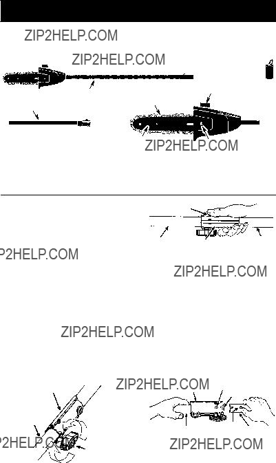
STie cord to cord retainer and connect to re- cessed plug as shown in this manual to pre- vent damage to unit and/or extension cord and to reduce the possibility of the exten-

sion cord disconnecting from the unit during operation.

SDo not attempt to repair unit. Inspect the insu- lation and connectors on the unit and exten- sion cord before each use. If there is any damage, do not use until damage is repaired

by your authorized service dealer.

SDo not use the unit if the switch does not turn the unit on and off properly. Have the unit repaired by your authorized service dealer.

SDo not use with damaged cord or plug. If unit is not working as it should, has been dropped, damaged, left outdoors, or

dropped into water, return it to your autho- rized service dealer for repair.

SAvoid unintentional starting of the unit. Nev- er carry unit with your finger on the switch. Be sure the switch is in the off position and never touch the switch when connecting extension cord.

SUnplug the unit from the power source when not in use, before servicing, and when chang-

ing accessories and/or attachments.

S Avoid any body contact with any grounded conductor, such as metal fences, or pipes, to avoid the possibility of electric shock.

S Ground Fault Circuit Interrupter (GFCI) protection should be provided on the circuit

or outlet to be used for the unit. Receptacles are available having built-in GFCI protec-

tion and may be used for this measure of safety.

UNIT/MAINTENANCE SAFETY

WARNING: Always stop unit and dis- connect spark plug wire (or disconnect unit

from power source) before performing mainte- nance.

SInspect entire unit before each use. Replace damaged parts. Check for fuel leaks. Make sure all fasteners are in place and securely

fastened.

S Maintain unit according to recommended pro- cedures.

S Use only recommended Poulan PRO parts

and accessories.

S Be sure chain stops moving when engine

idles (see CARBURETOR ADJUST- MENTS section of original manual).

S Keep others away when making carburetor

adjustments.

S Never start the unit with the clutch housing re-

moved. The clutch can fly off and cause seri- ous injury.

SKeep the handles driy, clean, and free of oil or fuel mixture.

SKeep fuel and oil caps, screws, and fasteners securely tightened.

SHave all maintenance and service not ex- plained in this manual performed by an autho- rized service dealer.

OPERATE YOUR PRUNER SAFELY

SOperate the pruner only in a well-ventilated outdoor area.

S Do not use a pruner to cut down trees or any portion of the tree trunk.

S Only use for pruning limbs or branches overhead not greater than 6 inches (15 cm) in diameter.

SDo not cut small brush and saplings with the pruner. Slender matter may catch in the chain and be whipped toward you, pulling you off

balance.

SMake sure the chain will not make contact with any object while starting the engine. Never try to start the unit when the guide bar is in a cut.

4

SDo not put pressure on the pruner at the end of the cut. Applying pressure can cause you to lose control when the cut is completed.

SDo not run the unit at high speed when not pruning.

SIf you strike or become entangled with a for- eign object, stop the engine immediately and check for damage. Have any damage re- paired by an authorized service dealer before attempting further operations.

SDo not operate a pruner that is damaged, im- properly adjusted, or not completely and se- curely assembled. Always replace bar and chain immediately if it becomes damaged,

broken or is otherwise removed.

SAlways stop the unit when work is delayed or when walking from one cutting location to another. Stop the engine before setting the

unit down.

S Use only in daylight or good artificial light. S Use only for jobs explained in this manual.

KICKBACK

WARNING: Avoid kickback which

can result in serious injury. Kickback is the backward, upward or sudden forward motion of the guide bar occurring when the chain near the upper tip of the guide bar contacts any object such as a log or branch, or when the wood closes in and pinches the chain in the cut. Contacting a foreign object in the wood can also result in loss of control.

S Rotational Kickback can occur when the moving chain contacts an object at the upper

tip of the guide bar. This contact can cause the chain to dig into the object, which stops the chain for an instant. The result is a light- ning fast, reverse reaction which kicks the guide bar up and back toward the operator.

SPinch-Kickback can occur when the wood closes in and pinches the moving chain in the cut along the top of the guide bar and the chain is suddenly stopped. This sudden stopping of the chain results in a reversal of the chain force used to cut wood and causes the pruner to move in the opposite direction of the chain rotation. The pruner is driven straight back toward the operator.

S Pull-In can occur when the moving chain contacts a foreign object in the wood in the cut along the bottom of the guide bar and the chain is suddenly stopped. This sudden stop- ping pulls the pruner forward and away from the operator and could easily cause the oper- ator to lose control of the pruner.

REDUCE THE CHANCE OF

KICKBACK

SRecognize that kickback can happen. With a basic understanding of kickback, you can reduce the element of surprise which con- tributes to accidents.

SNever let the moving chain contact any ob- ject at the tip of the guide bar.

SKeep the working area free from obstruc- tions such as other trees, branches, rocks, stumps, etc. Eliminate or avoid any obstruction that your chain could hit while you are cutting. When cutting a branch, do

not let the guide bar contact branch or other objects around it.

SKeep your chain sharp and properly ten- sioned. A loose or dull chain can increase the chance of kickback occurring. Follow manufacturer???s chain sharpening and maintenance instructions. Check tension

at regular intervals with the engine stopped, never with the engine running. Make sure the bar clamp nut is securely tightened after tensioning the chain.

SBegin and continue cutting at full speed. If the chain is moving at a slower speed, there

is greater chance of kickback occurring. S Cut one branch at a time.

S Use extreme caution when re-entering a previous cut.

SDo not attempt cuts starting with the tip of the bar (plunge cuts).

SWatch for shifting of wood or other forces that could close a cut and pinch or fall into chain.

SUse the Reduced--Kickback Guide Bar and Low--Kickback Chain specified for your unit.

MAINTAIN CONTROL

SKeep a good, firm grip on the pruner with both hands when the engine is running and don???t let go. A firm grip will help you reduce kick- back and maintain control. Keep the fingers of your left hand encircling and your left thumb under the assist handle. Keep your right hand completely around the throttle handle whether your are right handed or left handed.

S Stand with your weight evenly balanced on both feet.

SStand slightly to the left side of the pruner to keep your body from being in a direct line with the cutting chain.

KICKBACK SAFETY FEATURES

The following features are included on your pruner to help reduce the hazard of kickback; however, such features will not totally eliminate this danger. As a pruner user, do not rely only on safety devices. You must follow all safety

precautions, instructions, and maintenance in this manual to help avoid kickback and other forces which can result in serious injury.

SReduced--Kickback Guide Bar, designed with a small radius tip which reduces the size of the kickback danger zone on the bar tip.

5

Reduced Kickback Symmetrical Guide Bar

Small Radius Tip

Symmetrical Guide Bar

Large Radius Tip

SLow--Kickback Chain, designed with a con- toured depth gauge and guard link which deflect kickback force and allow wood to gradually ride into the cutter.

Contoured Depth Gauge

Not a Low--- Kickback Chain

TRANSPORTING AND STORAGE

S Do not grasp or hold exposed blade. S Stop unit before leaving work area.

S Allow unit and gearbox to cool before storing or transporting it in a vehicle.

SStore unit and fuel in area where fuel vapors cannot reach sparks or open flames from wa- ter heaters, electric motors or switches, fur-

naces, etc.

S Store attachment so blade cannot accidental- ly cause injury.

SStore attachment indoors, out of reach of chil- dren.

If situations occur which are not covered in this manual, use care and good judgment. If you need assistance, call 1-800-554-6723.

SPECIAL NOTICE: Exposure to vibrations through prolonged use of gasoline powered hand tools could cause blood vessel or nerve damage in the fingers, hands, and joints of

people prone to circulation disorders or abnor- mal swellings. Prolonged use in cold weather has been linked to blood vessel damage in otherwise healthy people. If symptoms occur such as numbness, pain, loss of strength, change in skin color or texture, or loss of feeling in the fingers, hands, or joints, discontinue the use of this tool and seek medical attention. An anti-vibration system does not guarantee the avoidance of these problems. Users who oper-

ate power tools on a continual and regular basis must monitor closely their physical condition and the condition of this unit.

SAVE THESE INSTRUCTIONS

ASSEMBLY

WARNING: If received assembled, repeat all steps to ensure your unit is properly assembled and all fasteners are secure.

Examine parts for damage. Do not use dam- aged parts.

NOTE: If you need assistance or find parts missing or damaged, call 1-800-554-6723.

TOOLS REQUIRED

S Hex wrench (provided)

INSTALLING PRUNER ATTACH-

MENT

CAUTION: When removing or installing at- tachments, place the unit on a flat surface for stability.

NOTE: The pruner attachment connects to the engine end shaft through use of a coupler system. For extra reach, the extension shaft (included) can be used.

1.Loosen the couplers on the extension shaft and on the engine end shaft by turn- ing the knobs counterclockwise.

Coupler

AttachmentLOOSEN

Knob

TIGHTEN

2.Remove the shaft cap from the pruner at- tachment (if present).

3.Position locking/release button of attach- ment into guide recess of coupler on extension shaft.

4.Push the attachment into the coupler until the locking/release button snaps into the primary hole.

Coupler Primary Hole

Guide Recess

5.Repeat steps to attach extension shaft to coupler on engine end shaft.

6

6.Before using the unit, tighten both knobs securely by turning clockwise.

WARNING: Make sure the locking/ release button is locked in the primary hole of both couplers and the knobs are securely tightened before operating the unit. Using the wrong holes could lead to serious injury or dam- age to the unit.

Locking/Release

Button in Primary Hole

SHOULDER STRAP ASSEMBLY

WARNING: Proper shoulder strap and handle adjustments are required before use. The shoulder strap clamp must be installed as shown above the assist handle on the engine

end shaft.

NOTE: The lower shoulder strap clamp has two spacer tabs attached. These tabs are provided to adapt this attachment for use with units that have a 1 inch (2,5 cm) diameter shaft (the shoulder strap clamp will not tighten down securely on the 1 inch (2,5 cm) diameter shaft without using these spacer tabs). The tabs must be broken off completely before use and placed over the screw holes on the

lower shoulder strap clamp. These tabs are not needed for units with a 7/8??? (2,2 cm) shaft.

LOWER SHOULDER STRAP

CLAMP

Spacer Tabs

Spacer Tabs positioned for use

on 1 inch (2,5 cm) diameter shaft

1.Place the upper shoulder strap clamp over the shaft above the handlebar.

2.Position the lower shoulder strap clamp under the upper shaft and align the upper and lower clamp screw holes (use spacer tabs between upper and lower clamps if necessary to secure clamp, i.e. for 1??? di- ameter upper shaft).

Upper Shoulder

Strap Clamp

ENGINE/MOTOR

END

3.Insert two screws into the screw holes.

4.Secure shoulder strap clamp by tighten- ing screws with the hex wrench.

5.Try on shoulder strap and adjust for fit and balance before starting the engine or begin- ning a cutting operation.

6.Insert your right arm and head through the shoulder strap and allow it to rest on your left shoulder. Make sure the danger sign

is on your back and the hook is to the right side of your waist.

NOTE: A one-half twist is built in the shoul-

der strap to allow the strap to rest flat on the shoulder.

7.Adjust the strap, allowing the hook to be about 3 -- 6 inches (8 -- 15 cm) below the waist.

8.Fasten the strap hook to the upper clamp and lift the tool to the operating position.

Shoulder Strap

Shoulder

Strap

Clamp

ADJUSTING THE ASSIST HANDLE

WARNING: When adjusting the as- sist handle, be sure it remains directly above the coupler on the engine end shaft to ensure proper balancing of unit.

Assist Handle

Coupler

7

OPERATION

KNOW YOUR PRUNER ATTACHMENT

READ THIS INSTRUCTION MANUAL AND SAFETY RULES BEFORE OPERATING YOUR PRUNER ATTACHMENT. Compare the illustrations with your attachment to familiarize yourself with the location of the various controls and adjustments. Save this manual for future reference.

Pruner

Shaft

Extension Shaft

PRUNER

The PRUNER is designed for removal of limbs and branches overhead not greater than 6 inches (15 cm) in diameter.

Hanger

Bar Oil Fill Cap

Chain

CHAIN TENSION

It is normal for a new chain to stretch during first 15 minutes of operation. You should check your chain tension frequently. See CHAIN TENSION in the SERVICE AND AD- JUSTMENTS section.

OPERATING THE COUPLER

Your unit is equipped with a coupler which en- ables optional attachments to be installed. The optional attachments are:

MODEL:

Edger . . . . . . . . . . . . . . . . . . . . . . . PP1000E

Cultivator . . . . . . . . . . . . . . . . . . . . PP2000T Blower . . . . . . . . . . . . . . . . . . . . . . PP3000B Pruner . . . . . . . . . . . . . . . . . . . . . . PP5000P Brushcutter* . . . . . . . . . . . . . . . . . PP4000C *not designed for use with electric-powered motors.

WARNING: Always stop unit and dis- connect spark plug wire (or disconnect unit from power source) before removing or instal- ling attachments.

REMOVING PRUNER ATTACHMENT

(OR OTHER OPTIONAL ATTACH-

MENTS)

CAUTION: When removing or installing at- tachments, place the unit and attachment on a flat surface for stability.

1.Loosen the coupler by turning the knob counterclockwise.

Coupler

Locking/Release

Button

3.While securely holding the engine end shaft and extension shaft, pull the attachment straight out of the extension shaft coupler.

4.Repeat steps to remove extension shaft from coupler on engine end shaft.

INSTALLING OPTIONAL ATTACH-

MENTS

CAUTION: DO NOT use extension shaft with other optional attachments.

1.Remove the shaft cap from the attachment (if present) and discard.

2.Position locking/release button of attach- ment into guide recess of coupler on engine end shaft.

3.Push the attachment into the coupler until the locking/release button snaps into the primary hole.

4.Before using the unit, tighten the knob se- curely by turning clockwise.

Coupler Primary Hole

Guide Recess

AttachmentLOOSEN

Locking/

Upper Release Attachment

Shaft Button

Knob

TIGHTEN

2. Press and hold the locking/release button.

8

WARNING: Make sure the locking/ release button is locked in the primary hole and the knob is securely tightened before op- erating the unit. Using the wrong hole could lead to serious injury or damage to the unit.

Locking/Release

Button in Primary Hole

BAR AND CHAIN LUBRICATION

The bar and chain require lubrication. The chain oiler provides continuous lubrication to the chain and guide bar. Be sure to fill the bar oil tank before use (Capacity = 4.6 fl. oz.). Lack of oil will quickly ruin the bar and chain. Too little oil will cause overheating shown by smoke coming from the chain and/or discolor- ation of the bar. The oil output is automatically metered during operation.

Genuine Poulan or Poulan PRO bar and chain oil is recommended to protect your unit against excessive wear from heat and fric- tion. Poulan or Poulan PRO oil resists high

temperature thinning. If Poulan or Poulan PRO bar and chain oil is not available, use a good grade SAE 30 oil.

SNever use waste oil for bar and chain lubri- cation.

S Always stop the engine before removing the oil cap.

INSTALLING ATTACHMENT

HANGER

An attachment hanger is provided for storage when attachment is not in use.

To install hanger on attachment:

1.Remove the shaft cap from the attachment (if present) and discard.

2.Press and hold the locking/release button.

3.Push hanger onto the attachment until the locking/release button snaps into the hole.

OPERATING POSITION

ALWAYS WEAR:

Head

Protection Eye

Protection

Long Pants

Heavy Shoes

DANGER: Do not extend arms above shoulders while pruning. Do not stand be- neath branch being cut.

WARNING: Always wear head, eye, hearing, foot and body protection to reduce the risk of injury when operating this unit.

When operating unit, clip shoulder strap onto clamp, stand as shown and check for the fol-

lowing:

SExtend your left arm and hold assist handle with your left hand.

SHold throttle grip with your right hand with finger on throttle trigger.

S Keep engine end below waist level.

SKeep shoulder strap pad centered on your left shoulder and danger sign centered on

your back.

S Maintain full weight of tool on your left shoulder.

PRUNING

WARNING: Be alert for and guard against kickback. Do not allow the moving chain to contact any other branches or objects at the

nose of the guide bar when pruning. Allowing such contact can result in serious injury.

IMPORTANT POINTS

S Work slowly, keeping both hands firmly

gripped on the pruner. Maintain secure foot- ing and balance.

S Plan cut carefully. Check direction branch will fall.

S Watch out for springpoles. Springpoles are small size limbs which can catch the chain and whip toward you or pull you off balance. Use extreme caution when cutting small size limbs or slender material.

S Watch out for branches immediately behind the branch being pruned. If the chain hits the rear branch, damage to the unit may occur.

S Be alert for springback. Watch out for branches that are bent or under pressure. Avoid being struck by the branch or the pruner when the tension in the wood fibers is released.

SKeep a clear work area. Frequently clear branches out of the way to avoid tripping

over them.

SLong branches should be removed in sev- eral pieces.

PRUNING TECHNIQUE

When ready to cut, accelerate to full throttle and apply a light cutting pressure. DO NOT use back and forth sawing action.

9

Second cut

Third cut

Collar

First cut

Pruning technique

1.Make the first cut 6 inches from the tree trunk on the bottom of the limb. Use top of guide bar to make this cut. Cut 1/3 through the diameter of the limb.

NOTE: When making the second and third cuts, rest the foot of the pruner against the tree limb that is being cut to prevent whipping of the branch.

Foot

2.Next, move 2 -- 4 inches farther out on the limb and make a second cut all the way through the limb.

3.Then, make a final cut leaving a 1 -- 2 inch collar from the trunk of the tree to avoid damage to the tree.

MAINTENANCE

WARNING: Always stop unit and dis- connect spark plug wire (or disconnect unit from power source) before performing main-

tenance.

CHECK FOR DAMAGED OR

WORN PARTS

Contact an authorized service dealer for re- placement of damaged or worn parts.

SOil tank -- Discontinue use of pruner attach- ment if oil tank shows signs of damage or leaks.

CHECK FOR LOOSE

FASTENERS AND PARTS

S Bar clamp nut

S Fasteners

INSPECT AND CLEAN UNIT AND

DECALS

S After each use, inspect complete unit for loose or damaged parts. Clean the unit and decals using a damp cloth with a mild deter- gent.

S Wipe off unit with a clean dry cloth.

CHECK CHAIN TENSION

WARNING: Wear protective gloves when handling chain. The chain is sharp and can cut you even when it is not moving. Make chain adjustments with lower end supported. Chain tension is very important. Chains

stretch during use. This is especially true dur- ing the first few times you use your pruner. Al- ways check chain tension each time you use and refuel your unit.

1.Use a screwdriver to move chain around guide bar to ensure kinks do not exist. The chain should rotate freely.

Chain Adjustment Tool

Guide

Bar

2.Loosen bar clamp nut until it is finger tight against the bar clamp.

3.Turn adjusting screw clockwise until chain solidly contacts bottom of guide bar rail. Then, turn adjusting screw an addi- tional 1/4 turn.

Adjusting Screw -- 1/4 Turn

4.Using a screwdriver, roll chain around guide bar to ensure all links are in bar groove.

5.Lift up tip of guide bar to check for sag. Release tip of guide bar, then turn adjust- ing screw 1/4 turn clockwise. Repeat until sag does not exist.

6.While lifting tip of guide bar, tighten bar clamp nut securely with a wrench.

10

7.Use a screwdriver to move chain around guide bar.

8.If chain does not rotate, it is too tight. Slightly loosen bar clamp nut and loosen chain by turning the adjusting screw 1/4 turn counterclockwise. Retighten bar clamp nut.

9.If chain is too loose, it will sag below the guide bar and needs to be tightened fol- lowing above procedure.

WARNING: DO NOT operate the pruner if the chain is loose. If the pruner is op-

erated with a loose chain, the chain could jump off the guide bar and result in serious in- jury.

CHECK CHAIN SHARPNESS

A sharp chain makes wood chips. A dull chain makes a sawdust powder and cuts slowly. See CHAIN SHARPENING in the SERVICE AND ADJUSTMENTS section.

BAR MAINTENANCE

If your pruner cuts to one side, has to be forced through the cut, or been run with an im- proper amount of bar lubrication it may be necessary to service your bar. A worn bar will damage your chain and make cutting difficult.

After each use, ensure ON/STOP switch is in the STOP position, then clean all sawdust from the guide bar and sprocket hole.

To maintain guide bar:

SMove ON/STOP switch to the STOP posi- tion and disconnect spark plug (or discon- nect unit from power source).

SLoosen and remove bar clamp nut and chain brake. Remove bar and chain from pruner.

S Clean the oil holes and bar groove after each 5 hours of operation.

Remove Sawdust From

Guide Bar Groove

Oil Holes

S Burring of guide bar rails is a normal process of rail wear. Remove these burrs with a flat file.

SWhen rail top is uneven, use a flat file to re- store square edges and sides.

File Rail Edges

and Sides

Square

Replace guide bar when the groove is worn, the

guide bar is bent or cracked, or when excess heating or burring of the rails occurs. If replace- ment is necessary, use only the guide bar speci- fied for your pruner in the repair parts list.

LUBRICATION

Bar Oil

Fill Cap

SSee GUIDE BAR AND CHAIN OIL under the OPERATION section.

SERVICE AND ADJUSTMENTS

WARNING: Always stop unit and dis- connect spark plug wire (or disconnect unit from power source) before performing main- tenance, service, or adjustments except for carburetor adjustments.

CHAIN SHARPENING

WARNING: Improper chain sharpen- ing techniques and/or depth gauge mainte-

nance will increase the chance of kickback which can result in serious injury.

WARNING: Wear protective gloves when handling chain. The chain is sharp and can cut you even when it is not moving.

Conditions which indicate the need for chain sharpening:

SReduction in size of wood chips. The size of the wood chip will decrease as the chain gets duller until it becomes more like a pow- der than a chip. Note that dead or rotted wood will not produce a good chip.

S Saw cuts to one side or at an angle. S Saw has to be forced through the cut.

Tools required:

S 3/16 inch (4,5 mm) diameter round file and file holder

S Flat file

S Depth gauge tool

TO SHARPEN CHAIN:

1.Move ON/STOP switch to the STOP posi- tion and disconnect spark plug (or discon- nect powerhead from power source).

2.Check chain for proper tension. Adjust chain tension if necessary. See CHECK CHAIN TENSION section.

3.Sharpen cutters.

STo sharpen the cutters, position the file holder level (90??) so that it rests on the top edges of the cutter and depth gauge. NOTE: The chain has both left and right hand cutters.

11

File Holder

File

4. Check and lower depth gauges.

Cutter

90??

Depth Gauge

Depth Gauge

SAlign the 30?? file holder marks parallel with the bar and to the center of the chain.

Cutter

SSharpen cutters on one side of the chain first. File from the inside of each cutter to the outside. Then, turn the chain saw around and repeat the process for the other side of the chain.

SFile on the forward stroke only. Use 2 or 3 strokes per cutting edge.

SKeep all cutters the same length when filing.

SFile enough to remove any damage to cutting edges (side plate and top plate of cutter).

SFile chain to meet the specifications as shown.

75??60??

30??

Hook Angle

S Place gauge tool on cutter.

SIf the depth gauge is higher than the depth gauge tool, file it level to the top of the depth gauge tool.

SMaintain rounded front corner of depth gauge with a flat file.

NOTE: The very top of the depth

gauge should be flat with the front half rounded off with a flat file.

If you require further assistance or are unsure

about performing this procedure, contact your authorized service dealer or call our customer assistance help line at 1--800--554--6723.

CHAIN REPLACEMENT

WARNING: Wear protective gloves when handling chain. The chain is sharp and can cut you even when it is not moving.

It is normal for a new chain to stretch during the first 15 minutes of operation. You should re- check your chain tension frequently and adjust the chain tension as required. See CHAIN TEN-

SION section.

Replace the old chain when it becomes worn or damaged. Use only the Low-Kickback replace- ment chain specified in the repair parts list.

TO REPLACE CHAIN:

1.Move ON/STOP switch to the STOP posi- tion and disconnect spark plug (or discon- nect unit from power source).

2.Remove bar clamp nut.

3.Remove bar clamp.

4.Turn adjusting screw by hand counter- clockwise until adjusting pin just touches the stop.

5.Slide guide bar behind sprocket until guide bar stops against sprocket.

6.Remove the old chain.

7.Carefully remove new chain from pack- age. Hold chain with the drive links as shown.

Cutter

Tip of

Bar

Drivelink

CUTTERS MUST FACE IN

DIRECTION OF ROTATION

Wrong

WARNING: Maintain the proper hook angle according to the manufacturer???s specifica- tions for the chain you are using. Improper hook angle will increase the chance of kickback which can result in serious injury.

Drive Links

12

8.Place chain over sprocket, fitting the drive links in the sprocket.

9.Fit bottom of drive links between the teeth in the sprocket in the nose of the guide bar.

10.Fit chain drive links into bar groove.

11.Pull guide bar forward until chain is snug in guide bar groove. Ensure all drive links are in the bar groove.

12.Now, install bar clamp making sure the adjusting pin is positioned in the lower hole in the guide bar.

Lower Hole

Adjusting Pin

Guide Bar

13.Install bar clamp nut and finger tighten only. Do not tighten any further at this point. Proceed to the CHAIN ADJUST- MENT section.

CHAIN ADJUSTMENT

See CHECK CHAIN TENSION in MAINTE- NANCE section.

USER REPLACEABLE SERVICE PARTS

Use only recommended user replaceable service parts as listed below:

STORAGE

WARNING: Perform the following steps after each use:

S Allow attachment to cool before storing or transporting.

SStore attachment with all guards in place. Position attachment so that any sharp ob-

ject cannot accidentally cause injury.

SStore the attachment in a dry, well venti- lated area out of the reach of children.

SEASONAL STORAGE

Prepare attachment for storage at end of sea- son or if it will not be used for 30 days or more.

If your pruner attachment is to be stored for a period of time:

S Clean the entire attachment.

S Lightly oil external metal surfaces and guide bar.

SOil the chain and wrap it in heavy paper or cloth.

SCheck entire attachment for loose screws or nuts. Replace any damaged, worn or broken parts.

SAt the beginning of the next season, use only fresh fuel having the proper gasoline to oil ratio.

13

LIMITED WARRANTY

Poulan PRO, a division of Husqvarna Consum- er Outdoor Products N.A., Inc., warrants to the

original consumer purchaser that each new Poulan PRO brand gasoline tool or attachment is free from defects in material and workman- ship and agrees to repair or replace under this warranty any defective gasoline product or at- tachment as follows from the original date of purchase.

2 YEARS - Parts and Labor, when used for household purposes.

90 DAYS - Parts and Labor, when used for

commercial, professional, or income producing purposes.

30 DAYS - Parts and Labor, if used for rental purposes.

This warranty is not transferable and does not cover damage or liability caused by improper handling, improper maintenance or alteration, or the use of accessories and/or attachments not specifically recommended by Poulan PRO for this tool. This warranty does not cover bars, chains or parts that will wear and require re- placement with reasonable use during the war- ranty period. This warranty does not cover pre-- delivery setup or normal adjustments explained

in the instruction manual. This warranty does not cover transportation costs.

In the event you have a claim under this warran- ty, you must return the product to an authorized service dealer.

Should you have any unanswered questions concerning this warranty, please contact: Poulan PRO, a division of Husqvarna Consumer Outdoor Products N.A., Inc.

7349 Statesville Road

Charlotte, NC 28269 1--800--554--6723

In Canada, contact:

Poulan PRO

850 Matheson Blvd. West Mississauga, Ontario L5V 0B4

Giving the model number, serial number and date of purchase of your product and the name and address of the authorized dealer from whom it was purchased.

THIS WARRANTY GIVES YOU SPECIFIC

LEGAL RIGHTS, AND YOU MAY HAVE OTH-

ER RIGHTS WHICH VARY FROM STATE TO

STATE.

NO CLAIMS FOR CONSEQUENTIAL OR

OTHER DAMAGES WILL BE ALLOWED,

AND THERE ARE NO OTHER EXPRESS

WARRANTIES EXCEPT THOSE EX-

PRESSLY STIPULATED HEREIN.

SOME STATES DO NOT ALLOW LIMITA-

TIONS ON HOW LONG AN IMPLIED WAR-

RANTY LASTS OR THE EXCLUSION OR

LIMITATIONS OF INCIDENTAL OR CONSE-

QUENTIAL DAMAGES, SO THE ABOVE LIM-

ITATIONS OR EXCLUSION MAY NOT APPLY

TO YOU.

This is a limited warranty within the meaning of that term as defined in the Magnuson--Moss Act

of 1975.

The policy of Poulan PRO is to continuously improve its products. Therefore, Poulan PRO reserves the right to change, modify, or discontinue models, designs, specifications, and accessories of all products at any time without notice or obligation to any purchaser.

14