hard hat; and sound barriers (ear plugs or mufflers) to protect your hearing. Regular users should have hearing checked regular- ly as chain saw noise can damage hearing. Secure hair above shoulder length.
SKeep all parts of your body away from the chain when the engine is running.
SKeep children, bystanders, and animals a minimum of 30 feet (10 meters) away from the work area. Do not allow other people or animals to be near the chain saw when starting or operating the chain saw.
S Do not handle or operate a chain saw when you are fatigued, ill, or upset, or if you have taken alcohol, drugs, or medication. You must be in good physical condition and mentally alert. Chain saw work is strenuous. If you have any condition that might be aggravated by strenuous work, check with your doctor before operating a chain saw.
SCarefully plan your sawing operation in ad- vance. Do not start cutting until you have a clear work area, secure footing, and, if you are felling trees, a planned retreat path.
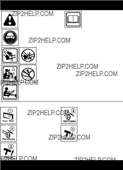
OPERATE YOUR SAW SAFELY
SDo not operate a chain saw with one hand. Serious injury to the operator, helpers, by- standers or any combination of these per- sons may result from one-handed opera- tion. A chain saw is intended for
two-handed use.
SOperate the chain saw only in a well-venti- lated outdoor area.
S Do not operate saw from a ladder or in a tree.
SMake sure the chain will not make contact with any object while starting the engine. Never try to start the saw when the guide bar is in a cut.
SDo not put pressure on the saw at the end of the cut. Applying pressure can cause you to lose control when the cut is com- pleted.
S Stop the engine before setting the saw down.
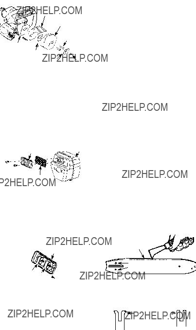
SDo not operate a chain saw that is dam- aged, improperly adjusted, or not com- pletely and securely assembled. Always replace bar, chain, hand guard, or chain brake immediately if it becomes damaged, broken or is otherwise removed.
SWith the engine stopped, hand carry the chain saw with the muffler away from your body, and the guide bar and chain to the rear, preferably covered with a scabbard.
MAINTAIN YOUR SAW IN GOOD
WORKING ORDER
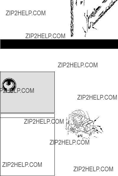
SHave all chain saw service performed by a qualified service dealer with the exception of the items listed in the maintenance sec- tion of this manual. For example, if improp- er tools are used to remove or hold the fly- wheel when servicing the clutch, structural damage to the flywheel can occur and
cause the flywheel to burst.
SMake certain the saw chain stops moving when the throttle trigger is released. For
correction, refer to CARBURETOR AD-
JUSTMENTS.
S Never modify your saw in any way.
S Keep the handles dry, clean, and free of oil or fuel mixture.
SKeep fuel and oil caps, screws, and fas- teners securely tightened.
S Use only Poulan accessories and re- placement parts as recommended.
HANDLE FUEL WITH CAUTION
SDo not smoke while handling fuel or while operating the saw.
SEliminate all sources of sparks or flame in the areas where fuel is mixed or poured. There should be no smoking, open flames, or work that could cause sparks. Allow en- gine to cool before refueling.
S Always have fire extinguishing tools avail- able if you should need them.
SMix and pour fuel in an outdoor area on bare ground; store fuel in a cool, dry, well ventilated place; and use an approved, marked container for all fuel purposes. Wipe up all fuel spills before starting saw.
SMove at least 10 feet (3 meters) from fuel- ing site before starting engine.
STurn the engine off and let saw cool in a non-combustible area, not on dry leaves, straw, paper, etc. Slowly remove fuel cap and refuel unit.
SStore the unit and fuel in an area where fuel vapors cannot reach sparks or open flames from water heaters, electric motors or switches, furnaces, etc.
KICKBACK
 WARNING: Avoid kickback which
can result in serious injury. Kickback is the backward, upward or sudden forward motion of the guide bar occurring when the saw chain near the upper tip of the guide bar contacts any object such as a log or branch, or when the wood closes in and pinches the saw chain in the cut. Contacting a foreign object in the wood can also result in loss of chain saw control.
SRotational Kickback can occur when the
moving chain contacts an object at the up- per tip of the guide bar. This contact can cause the chain to dig into the object, which stops the chain for an instant. The result is a lightning fast, reverse reaction which kicks the guide bar up and back to- ward the operator.
3


 Small Radius Tip


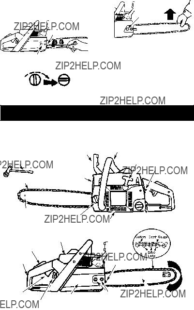
 Adjusting screw


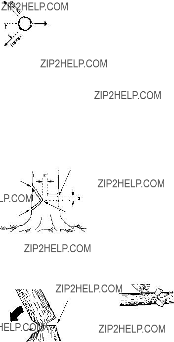


 of notch

 2
2


 Depth Gauge


 Moderate (50 hours)