SThis saw is equipped with a chain brake. The brake is designed to stop the chain if
kickback occurs.
S The inertia--activated chain brake is activated if the front hand guard is pushed forward, either manually (by hand) or automatically (by sudden movement).
S If the brake is already activated, it is disengaged by pulling the front hand guard back toward the front handle as far as possible.
SWhen cutting with the saw, the chain brake must be disengaged.
Disengaged
Engaged
Braking function control CAUTION: The chain brake must be
checked several times daily. The engine must be running when performing this proce- dure. This is the only instance when the saw should be placed on the ground with the en- gine running.
Place the saw on firm ground. Grip the rear handle with your right hand and the front han- dle with your left hand. Apply full throttle by fully depressing the throttle trigger. Activate the chain brake by turning your left wrist against the hand guard without releasing
your grip around the front handle. The chain should stop immediately.
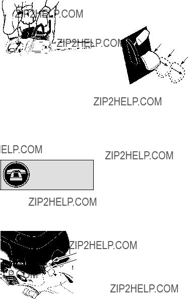
Inertia activating function control
 WARNING: When performing the
following procedure, the engine must be turned off.
Grip the rear handle with your right hand and
the front handle with your left hand. Hold the chain saw approximately 14??? (35 cm) above a stump or other wooden surface. Release your grip on the front handle and use the weight of the saw to let the tip of the guide bar fall forward and contact the stump. When the tip of the bar hits the stump, the brake should activate.
OPERATING TIPS
SCheck chain tension before first use, after 1 minute of operation, and each time be- fore you start the chain saw. See CHAIN TENSION in the ASSEMBLY section.
S Cut wood only. Do not cut metal, plastics, masonry, non-wood building materials, etc.
SStop the saw if the chain strikes a foreign object. Inspect the saw and repair or re- place parts as necessary. If the chain jumps off the guide bar, inspect the chain for damaged drive links before reinstalling. Burrs on drive links, which prevent them from entering the groove of the guide bar, can be removed with a flat file.
SKeep the chain out of dirt and sand. Even a small amount of dirt will dull a chain, increase the possibility of kickback, and require chain sharpening or replacement.
SPractice cutting a few small logs using the following techniques to get the ???feel??? of us- ing your saw before you begin a major sawing operation.
S Squeeze the throttle trigger and allow the engine to reach full speed before cutting.
S Begin cutting with the saw frame
against the log.
SKeep the engine at full speed the entire time you are cutting.
SAllow the chain to cut for you. Exert only light downward pressure. If you force the cut, damage to the bar, chain, or en-
gine can result.
SRelease the throttle trigger as soon as the cut is completed, allowing the en- gine to idle. If you run the saw at full throttle without a cutting load, unneces- sary wear can occur to the chain, bar, and engine. It is recommended that the engine not be operated for lon-
ger than 30 seconds at full throttle.
STo avoid losing control when cut is com- plete, do not put pressure on saw at end
of cut.
S Stop the engine before setting the saw down after cutting.
TREE FELLING TECHNIQUES
 WARNING: Check for broken or
dead branches which can fall while cutting causing serious injury. Do not cut near build- ings or electrical wires if you do not know the
direction of tree fall, nor cut at night since you will not be ale to see well, nor during bad weather such as rain, snow, or strong winds, etc. If the tree makes contact with any utility line, the utility company should be notified immediately.
SCarefully plan your sawing operation in ad- vance.
S Clear the work area. You need a clear area all around the tree so you can have secure footing.
SThe chain saw operator should keep on the uphill side of the terrain as the tree is likely to roll or slide downhill after it is felled.
SStudy the natural conditions that can cause the tree to fall in a particular direction.
Natural conditions that can cause a tree to fall in a particular direction include:
S The wind direction and speed.
S The lean of the tree. The lean of a tree might not be apparent due to uneven or sloping terrain. Use a plumb or level to de- termine the direction of tree lean.
S Weight and branches on one side.
S Surrounding trees and obstacles.
Look for decay and rot. If the trunk is rotted, it can snap and fall toward the operator. Check for broken or dead branches which can fall on you while cutting.
Make sure there is enough room for the tree to fall. Maintain a distance of 2-1/2 tree lengths from the nearest person or other objects. En- gine noise can drown out a warning call.
Remove dirt, stones, loose bark, nails, sta- ples, and wire from the tree where cuts are to be made.


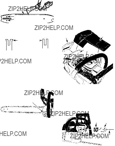
 Small Radius Tip


 Chain Adjustment
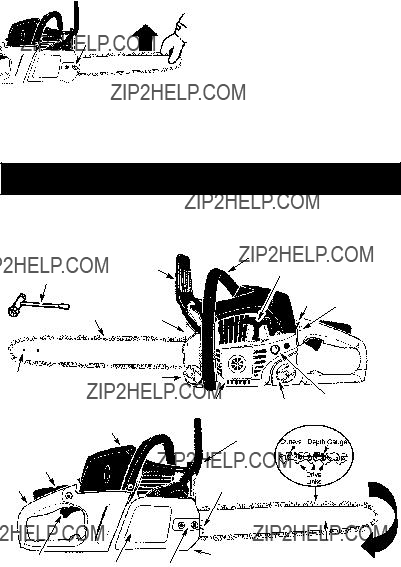


 Choke
Choke


 2
2


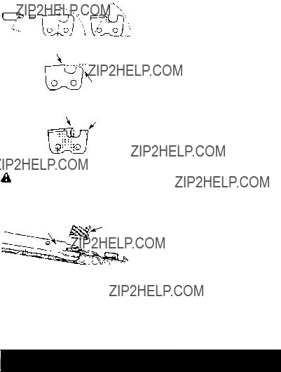
 Depth Gauge


 Intermediate (125 hours)