Gripper
&
Experimenter???s Module
Manual
version 1.2
Gripper
&
Experimenter???s Module
Manual
version 1.2

Gripper & Experimenter???s Module
Copyright 1997, ActivMedia, Inc. All rights reserved.
Under international copyright laws, this manual or any portion of it may not be copied or in any way duplicated without the expressed written consent of ActivMedia, Inc.
The Saphira libraries and Pioneer software on disk and on the Pioneer server EPROM that accompany the robot and accessories and which are available for network download by Pioneer 1 customers are solely owned and copyrighted by Kurt Konolidge and SRI International. Pioneer 1 developers and users are authorized by revocable license to develop and operate custom software for personal, research, and educational use only. Duplication, distribution,
Real World Interface (RWI), Inc. manufactures the Pioneer 1 Mobile Robot and Gripper/Experimenter???s Module accessories. The various names and logos for products used in this manual are registered trademarks or trademarks of their respective companies. Mention of any
ii
Pioneer Gripper & Experimenter???s Module Manual version 1.2, August 1997.
iii
iv
Gripper & Experimenter???s Module
1.Introduction
Congratulations on your purchase and welcome to the rapidly growing community of researchers, developers, and enthusiasts of the Pioneer 1 Mobile Robot.
This Pioneer 1 Gripper & Experimenter???s Module Manual provides the general and technical details you will need to install and operate your new Gripper and to develop your own
attachments and enhancements for the Pioneer 1 Mobile Robot with the integrated Experimenter???s Module.
We also encourage you to use these companion resources that come with your Pioneer:
'Pioneer Operation Manual
'Saphira Software Manual
'Pioneer Registration & Account Sheet
'Personal account for the http://css.activmedia.com Internet server
'Pioneer- and
2.1Gripper and Experimenter???s Package
Our experienced robotics manufacturing staff put your Pioneer 1 Gripper and Experimenter???s Module through a
Even though we???ve made every effort to make your package complete, please check the components once again after you unpack it from the shipping crate.
2.1.1Package Components
'Pioneer 1 Gripper & Experimenter???s Module Assembly
'32K EPROM containing latest PSOS
'Gripper & Experimenter???s Module Manual
2.1.2User Supplied Components
'Pioneer 1 Mobile Robot
'Set of hex wrenches that accompanied original robot
'Small,
'Optional
1

Overview
2.2 Basic Pioneer Platform
Pioneer 1 is a small, mobile robot developed by Kurt Konolige of SRI International and Grinnell More of Real World Interface, Inc., and is available exclusively through ActivMedia, Inc.
The basic Pioneer 1 Mobile platform contains all of the components for sensing and navigation in a
Figure
The Pioneer 1 also comes with the Pioneer Server Operating System (PSOS) software on EPROM for easy access and control of the robot???s systems, an RS232 serial port for communication between the robot and other computers, as well as a variety of expansion I/O ports for optional and custom attachments.
2.3 The Gripper & Experimenter???s Module
The Pioneer 1 Experimenter???s Module essentially is a circuit board and accessory electronics that extend the capabilities of the Pioneer 1 microcontroller???s standard I/O ports, including electrical support for the Pioneer Gripper. The Experimenter???s Module is part of the Pioneer Gripper assembly, which together replace the nose the of basic robot (see Figures
2.3.1 Gripper Description
The Pioneer Gripper is a simple, yet powerful
2
Gripper & Experimenter???s Module
Figure
Figure
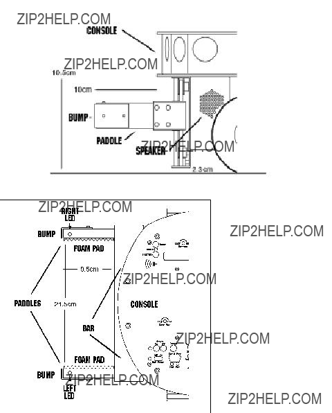
In its fully down/open state, the two 2.5 inch (5cm) tall by 3.5 inch (9.5cm) deep Gripper paddles (each with 0.5cm foam pads on the inside) are 8.5 inches (21.5cm) apart and ride 1 inch (2.3cm) off the floor. The paddles extend out from the front robot???s main body 3 inches (10cm) beyond the console edge.
3
Overview
In transition from the fully down/open position to their up/closed state, the Gripper paddles close together horizontally until they pinch an object or close on themselves. At that point, the entire Bar and Gripper Assembly rises up
The reverse cycle lowers the Gripper Bar and paddles to the bottom of the assembly, whereupon the paddles separate, dropping any contents, and open to their fully down/open position.
Two ???bump???
Three other switches sense the Gripper???s paddle positions. One switch inside the Bar is on when the Gripper paddles are in their fully open position. Another at the top of the Bar toggles on when the Gripper reaches its fully up position. A third ???carry??? switch, located behind the Bar, indicates when the Gripper is between 1.5 and 2 inches
2.3.2 Experimenter???s Module Description
The Experimenter???s Module includes several additional features that users may enable through the Pioneer I/O controls: There are green ???directional??? LEDs embedded in the tip of each paddle and at the top of each side, facing front on the Gripper???s back plate. On the left side of the Gripper, there is a speaker, an SPST
Figure
Inside and on the Experimenter???s Module is a bank of eight
4

Gripper & Experimenter???s Module
digital ports. There also is circuitry and a connector for an
A complete list of available I/O ports and connections can be found in Chapter 4,
Experiment???s Module.
2.4 Additional Resources
Every Pioneer 1 customer gets three additional and valuable resources: a private account on ActivMedia???s Internet server for downloading Pioneer software, updates, and manuals, access to RWI???s private robotics newsgroups, and
2.4.1 Pioneer Web Software Archive
We have a World Wide Web server connected continuously to the Internet where customers may obtain Pioneer 1 software and support materials. Point your favorite Web browser to:
http://css.activmedia.com
Some access areas are restricted to licensed customers, including Pioneer owners. To gain restricted access, use the username and password that are written on the Pioneer 1
Registration & Account Sheet that accompanied your robot.
2.4.2 Pioneer and Saphira Newsgroups
RWI also maintains a special
To: majordomo@rwii.com
From: <your return
Subject: help (Subject: always ignored)
(body of
5
Overview
2.4.3 Support
Have a problem? Can???t find the answer in this or any of the accompanying manuals? Know a way that we might improve Pioneer 1? Share your thoughts and questions directly with us:
Your message goes to our team of Pioneer developers who will help you directly or point you to where you may find help. Because this is a support option, not a general- interest newsgroup like
6
Gripper & Experimenter???s Module
3.Installation
Please read through this chapter carefully before you attempt to attach the Gripper & Experimenter???s Module to your Pioneer 1 Mobile Robot. If for any reason you do not wish to perform the work yourself, contact RWI and make arrangements to
have the assembly installed at the factory.
On the other hand, skip this chapter altogether if your Pioneer 1 Mobile Robot came with the Gripper & Experimenter???s Module Assembly already attached.
Turn OFF the Pioneer robot???s Main Power before installing the Gripper & Experimenter???s Module.
3.1.1 Step 1: Remove the Console
The Gripper & Experimenter???s Module Assembly???s various ports and accessories connect to the Pioneer microcontroller???s power and expansion I/O. Also, software support is provided through a special Pioneer Server Operating System (PSOS), which is stored on a 32K EPROM mounted on the microcontroller. Accordingly, to install the Gripper/Experimenter???s Module and new PSOS, you must first disassemble the Pioneer Console.
With one of the hex wrenches that came with your robot, remove the six outermost screws that secure the top plate to the
If one is attached, carefully unplug and remove the Pioneer camera from the Console and back panel. Also unscrew and remove the radio modem antenna, if attached.
Twist
Gently lift the Console top plate to expose the microcontroller board, which is mounted to its underside, and the various wire harnesses attached to it. Being careful to not handle the attached microcontroller card, remove the wire connectors on both sides of the card from their sockets, freeing the Console top plate with the microcontroller card attached.
3.1.2 Step 2: Remove Microcontroller from Console
Lay the Console top plate face up, with the Pioneer 1 microcontroller card down, onto a clean, soft surface (first section of the Sunday Times is a great pad). Locate and remove the six hex
7

Installation
Figure
3.1.3 Step 3: Replace the
PSOS EPROM
Locate the EPROM/SRAM socket (Figure
EPROM.
Pry or pull out the socketed EPROM chip. We???d prefer that you use a special
if one isn???t handy, use a thin, flat-
bladed screwdriver and gently pry Figure
out of the socket freely.
EPROM chips are sensitive to static electricity. Be careful to handle them by their case and store them on conductive foam. Don???t touch the pins with your fingers, and be particularly careful not to bend any of their 28 delicate connector pins.
Now carefully remove the new PSOS EPROM that came with the Gripper/ Experimenter???s Module from its protective foam and insert it into the EPROM socket. Be sure to line up the Pin 1 notch and insert the pins in their respective socket holes. Then
8

Gripper & Experimenter???s Module
press carefully, but firmly down on the chip with your thumb or forefinger to seat it tightly in the socket.
3.1.4 Step 4 Reattach Microcontroller to Console
By reversing the procedures you took in Step 2 and using the same tools and screws, reattach the Pioneer microcontroller to the Console top plate. Set the entire assembly aside for the moment in a safe place.
3.1.5 Step 5 Remove Nose
The Gripper/Experimenter???s Module replaces the Pioneer???s nose. Use the hex wrenches that came with your robot to remove the six screws that secure the Nose to the Pioneer Deck and Body: four on top of the Deck and one on each side at the bottom. Store the Nose away.
3.1.6 Step 6 Connect Cables
Place the Gripper/Experimenter???s assembly on top of a table close to and in front of the Pioneer, with the Module card and attached flat ribbon cables facing the robot???s Nose. Push those three cables??? free connector ends through the opening in the nose and up into the Console. Similarly, push the Pioneer???s power cable through and out the Nose.
Plug the power cable attached to the Pioneer robot into its new
CAUTION: HOT POWER CABLE!
The Pioneer power cable is connected, unswitched, directly to the battery. Be careful to align the connector with its socket.
Misalignment may cause damage to the Pioneer microcontroller or to the Experimenter???s Module.
You may find that first unplugging the new power cable connector from its socket on the Module will expose the lower socket for easier attachment of the robot???s power connector. Do
3.1.7 Step 7 Attach Gripper/Experimenter???s Module to Pioneer
Use the hex wrenches that came with your robot and the screws you removed from the robot???s Nose to attach the Gripper/Experimenter???s Module to the Deck (4 screws; no screws attach to the Pioneer Body, as they do for the Nose).
9
Installation
3.1.8 Step 8
Carefully handling the Console top plate with attached microcontroller by its edges, reattach the various cables, front and back. Although the order is not critical, for convenience we recommend attaching the front cables first???the sonar and drive (left and right) cables.
Then, to the sockets on the rear of the microcontroller, attach the
3.1.9 Step 9
Align the Console
3.1.10 Step 10 Test the Assembly
Time to switch on the Pioneer???s Main Power and sniff for blue smoke. If sparks don???t fly and smoke is absent, the Pioneer will automatically exercise it???s new Gripper and finish with three loud and firm beeps through the newly attached
You???ve completed assembly and now are ready to run your Pioneer???s brand new gadgets. And for your troubles, you get two loose screws left over (they are the two round headed ones that came out of the bottom of the Nose).
10

Gripper & Experimenter???s Module
4.Gripper Operation and Programming
The Pioneer Gripper comes fully integrated with the robot???s systems and software. The latest versions of PSOS (4.2+) contains support for direct control of the Pioneer???s onboard I/O that run the Gripper functions, as well as
software control routines that manage the Gripper functions for you. In turn, these PSOS functions are supported in Saphira (version 5.3+), the Pioneer Application Interface (PAI), and
4.1 Gripper Self Test
Make sure the Pioneer motors are disengaged, if you perform the Gripper
The Gripper
Always place Pioneer 1 on the floor and have everyone step back before engaging the motors.
You may also test the Gripper???s open, up, and carry state switches. See the Experimenter???s Module, Digin I/O test mode section in Chapter 4 for details.
4.2 PSOS Server Information Packet
PSOS regularly sends Pioneer server information to a connected client over the serial communication line. Included in that Server Information Packet are the various states and readings from the Gripper and the Experimenter???s Module I/O. A summary of the PSOS Server Information Packet is in the Appendix B. These various readings may be captured and individually read by the client, or you may use the various Saphira, PAI, or
11

Gripper Operation and Programming
4.3 Gripper I/O
The Gripper???s single drive motor is controlled through two digital output lines and under control of the microcontroller CPU: Output port OD0 controls the direction of rotation and OD1 enables/disables the motor.
The act of gripping and raising objects is mechanical and dependent on the Gripper???s
Switches on top (???up???), inside at one end of the Bar (???open???), and behind the Bar (???carry???) indicate the various Gripper (G) positions (Table
Table
4.4 Gripper Programming
You can directly control the Gripper motor through the PSOS sfCOMDIGOUT command and byte parameters. PSOS also will accept a new state command, sfCOMGRIPPER, to achieve a gripper state, and sets the gripper motor bits appropriately. There also are some Saphira convenience functions defined for getting and setting the gripper state. For details on programming PSOS directly and through Saphira, consult the Saphira Software and Pioneer Operations and Software Manuals.
sfCOMDIGOUT control of Pioneer digital output ports has been changed in PSOS version 4.2 and later.
4.4.1 Direct Control via Digital Ports
12
Gripper & Experimenter???s Module
The revised PSOS 4.2 (and later) sfCOMDIGOUT command has a
The Saphira function, sfRobotCom2Bytes, packages the sfCOMDIGOUT command and values for you. For example:
sfRobotCom2Bytes(sfCOMDIGOUT, 0x20, 0x00)
resets bit 5 (OD0=0), and leaves everything else alone.
Accordingly, make the Gripper go up:
sfRobotCom2Bytes(sfCOMDIGOUT, 0x3, 0x3)
Go down:
sfRobotCom2Bytes(sfCOMDIGOUT, 0x3, 0x2)
And stop:
sfRobotCom2Bytes(sfCOMDIGOUT, 0x2, 0x00)
You have to monitor the various Gripper state switches to determine if and when it achieves a particular
4.4.2 State Commands
A more intelligent means of controlling the Gripper is through PSOS sfCOMGRIPPER command and state parameters. These automatically manage the Gripper so to achieve some
To operate the Gripper this way, you simply issue a state command to the robot. You don???t need to, but you may monitor the Gripper???s progress towards the state via bits 0 and 2 of the digout part of the server information packet (???sfROBOT.digoutput???). During transitions, the state returned by the robot is set to sfGRIPMOVING. After successfully achieving a state, the state returned is that state. If there is a
The various states and values are included in the script at the end of this chapter and that you may including in your own C programs.
There also are several Saphira convenience functions defined for gripper states:
int sfGripperGetState (void)
Returns the robot gripper state setpoint
void sfGripperSetState (int state)
Sets the robot gripper state setpoint
13

Gripper Operation and Programming
Table
/*************************************************************
*Gripper functions
*States are sfGRIPUP, sfGRIPDOWN, sfGRIPMIDDLE, sfGRIPOFF,
*and sfGRIPMOVING
*sfGRIPMOVING occurs only during transitions between states
*sfGRIPOFF can be set by the user, which means no state control
*sfGRIPOFF is set by the robot to indicate a timeout (6
*seconds) if a state is not achieved
*
**************************************************************/
/* states */
#define sfGRIPOFF 0 #define sfGRIPUP 1 #define sfGRIPMOVING 2 #define sfGRIPMIDDLE 4 #define sfGRIPDOWN 5 #define sfCOMGRIPPER 33
/* gripper control bits (DIGOUTPUT) */
#define sfGRIPSTATEMASK 0x05 /* picks out state bits in DIGOUTPUT */ #define sfGRIPMOTORBIT 0x02 /* motor bit, 0 is off, 1 is on */
14
Gripper & Experimenter???s Module
5.Experimenter???s Module
Besides hosting the Gripper, the Experimenter???s Module brings several new features to the Pioneer 1 Mobile Robot, and provides you with a platform for adding your own robotics options and features (Figure
'Easy access to Pioneer digital I/O, A/D, and timer functions
'Speaker with new PSOS ???say??? command
'
'8
'8
'
Figure
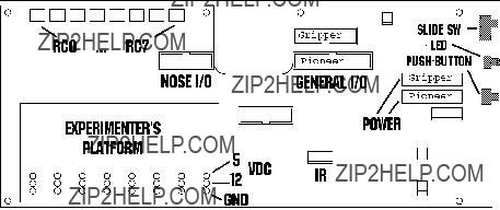
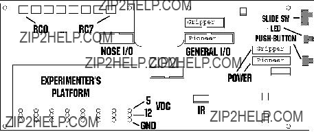
5.1 I/O Ports
By cables connected to the Pioneer microcontroller, the Experimenter???s Module brings both the Nose and General I/O expansion ports onto a single, open platform. All of ports now appear as solderable connections alongside a components pad, complete with power connections (Figure
The I/O ports and their uses are summarized in Table
15
Experimenter???s Module
Note also that the Nose (N)
16
Gripper & Experimenter???s Module
5.1.1 Digin:
You may investigate the operation of the digital input and output ports through their PSOS
After starting up your Pioneer, press the black Function button once to enable
BREAK, Boot to r eturn vv.vV*
indicating that Pioneer has entered
Skip to the digital input test by pressing the Function button 3 more times. The LCD should now read:
The E6 may
For example, if you press the user
Table
5.1.2 Digout:
Press the black Function button on the Console once more to set the Pioneer into a
17
Experimenter???s Module
5.2 Programming the Digital I/O Ports
Use the sfCOMDIGOUT PSOS command and the related Saphira convenience command to manage the various digital output ports. They are described in detail in the previous chapter. (PAI and
For example, to turn the right LED on, use:
sfRobotCom2Bytes(sfCOMDIGOUT, sfRIGHTLEDBIT, sfRIGHTLEDBIT)
Or alternatively, specify the state of an LED:
void sfGripperSetLed(int which, int state)
for which=sfLEFT or sfRIGHT, and state=sfON or sfOFF.
5.3 Programming the A/D Ports
The eight
Each AN port accepts a
For example, the following Saphira command addresses the AN4 port by masking the
sfRobotCom2Bytes(sfCOMDIGOUT, 0xE0, 0x80)
5.4 Programming the Speaker
The latest PSOS implements a new command called SAY, which plays a sequence of up to 20 notes through the Experimenter???s Module speaker. Now your Pioneer will be humming a different tune!
The SAY command (number 15) has two arguments: a string up to 40 bytes long, and the integer number of actual bytes in the string:
sfRobotComStrn(sfCOMSAY, str, n)
The string is comprised of duration and tone pairs; the duration byte is the number of 20 millisecond increments the following tone value
For example, to play two short, high beeps using the Saphira equivalent command:
void sfPlayToneString ("\010\002\010\000\010\002", 6)
18

Gripper & Experimenter???s Module
6.Maintenance & Repair
The Pioneer Gripper is built to last a lifetime and requires little maintenance.
6.1 Drive Lubrication
An occasional drop or two of oil on the guide rails is a very good idea. Place some thin, household oil on a
6.2 Gripper Belt Adjustments
The Gripper???s drive belts will stretch with use and may need to be tightened occasionally. We designed them to make that process easy.
Put the Gripper into its fully up
Do not remove the screw, but loosen it enough so that it will slide in that slot. (You may need to hold the fastening bolt behind the slot with pliers or a
6.3 Factory Repairs
If you are having hardware problems with your Pioneer 1 and, after reading this manual, you are satisfied that it needs repair, here???s who to contact:
In the body of your
We will try and resolve the problem through communication. If the robot must be returned to the factory for repair, obtain a shipping and repair authorization code and shipping details from us first. We are not responsible for shipping damage or loss.
19
7.Appendix A
Example C Program Demonstrates Gripper
and Speaker Functions
/* ################################################################
*gripper.c
**Copyright 1997 by Kurt Konolige
**
**The author hereby grants to SRI permission to use this software.
**The author also grants to SRI permission to distribute this software
**to schools for
**
**The author hereby grants to other individuals or organizations
**permission to use this software for
**educational use only. This software may not be distributed to others
**except by SRI, under the conditions above.
**
**Other than these cases, no part of this software may be used or
**distributed without written permission of the author.
**
**Neither the author nor SRI make any representations about the
**suitability of this software for any purpose. It is provided
**"as is" without express or implied warranty.
**
**Kurt Konolige
**Senior Computer Scientist
**SRI International
**333 Ravenswood Avenue
**Menlo Park, CA 94025
**
**/
#include "saphira.h" /*
* New comm function
(continued)
20
Gripper & Experimenter???s Module
void
sfRobotCom2Bytes(int com, int high, int low)
{
sfRobotComInt(com, ((high & 0xff)<<8) + (low & 0xff));
}
/*************************************************************
*Speaker functions
*Format of string is L1 T1 L2 T2 .... Ln Tn
*where Li is length of tone i in 20ms increments
*Max length of string is 40 bytes (20 tones)
**************************************************************/
void
sfPlayToneString(char *str, int n)
{
if (n > 40) n = 40; sfRobotComStrn(sfCOMSAY, str, n);
}
/*************************************************************
*Gripper functions
*
*States are sfUP, sfDOWN, sfMIDDLE, sfOFF, and sfMOVING
*sfMOVING occurs only during transitions between states
*sfOFF can be set by the user, which means no state control
*sfOFF can be set by the robot to indicate a timeout
*
**************************************************************/
#define sfGRIPMOVING 2 #define sfGRIPMIDDLE 4 #define sfGRIPDOWN 5 #define sfCOMGRIPPER 33
(continued)
21
/* gripper control bits (DIGOUTPUT) */
#define sfGRIPSTATEMASK 0x05 /* picks out state bits in DIGOUTPUT */ #define sfGRIPMOTORBIT 0x02 /* motor bit, 0 is off, 1 is on */
sfGripperGetState(void)
{
if (flakey.digoutput & sfGRIPMOTORBIT) return sfMOVING;
else
return flakey.digoutput & sfGRIPSTATEMASK;
sfGripperSetState(int state)
{
sfRobotComInt(sfCOMGRIPPER, state & sfGRIPSTATEMASK);
}
void/* sfLEFT, sfRIGHT, sfON, sfOFF */ sfGripperSetLed(int which, int state)
{
switch(which)
{
case sfLEFT:
which = sfLEFTLEDBIT;
break;
(continued)
22

Gripper & Experimenter???s Module
case sfRIGHT:
which = sfRIGHTLEDBIT;
break;
default:
which = 0;
}
switch(state)
{
case sfOFF:
sfRobotCom2Bytes(sfCOMDIGOUT, which, 0);
break;
case sfON:
sfRobotCom2Bytes(sfCOMDIGOUT, which, which);
break;
}
}
23
8.Appendix B
Pioneer Server Information Packet
24
9.Index
A
A/D, 18 A/D port, 15
ActivMedia, Inc., 2 Additional Resources, 5
B
break beams, 4
C
carry switch, 4 COMDIGOUT, 12, 13 COMGRIPPER, 12 components
package, 1
Pioneer 1, 2
COMSAY, 18
D
Digin, 17
E
EPROM location, 7 Experimenter???s Module
Description, 4 speaker, 18
Experimenter's Module, 15 components, 15
I/O ports, 15
F
FTP archives, 5
Gripper & Experimenter???s Module
G
General I/O, 16 GRIPMOVING, 13 GRIPOFF, 13 Gripper
Bar, 4
belt adjustments, 19 carry switch, 4 Description, 2 direct control, 13 I/O, 12
installation. See installation lubrication, 19 maintenance, 19
motor controls, 12 OD0, 12
OD1, 12 operating range, 3 operation, 11 paddles, 3
state commands, 13 state switches, 12 states, 2
switches, 4 transition cycle, 4
Gripper Bar, 4
Gripper I/O, 12
Gripper maintenance, 19 Gripper motor controls, 12 Gripper switches, 12 GripperGetState, 13
I
I/O
General, 16 Nose, 16
ports and connections, 16 programming, 18
I/O ports, 15 installation, 7 cables, 9
25
console removal, 7 EPROM location, 7 EPROM replacement, 7 microcontroller removal, 7
K
Konolige, Kurt, 2
L
LEDs, 18
M
majordomo, 5 microcontroller, 8
More, Grinnell, 2
N
newsgroups, 5 Nose I/O, 16
pinouts, 16
O
OD0, 12
OD1, 12
P
paddles
break beams, 4 positions, 4
paddles positions, 4 PAI, 11
Pioneer 1, 2
Pioneer Application Interface, 11
Pioneer Operations and Software Manual, 1 Pioneer Server Operating System. See
PSOS
PSOS, 11. See PSOS EPROM, 7
PSOS EPROM, 7
26
R
RWI, ii. See Real World Interface, Inc.
S
Saphira, 11 sfCOMDIGOUT, 12, 13 sfCOMGRIPPER, 12 sfCOMSAY, 18 sfGRIPMOVING, 13 sfGRIPOFF, 13 sfGripperGetState, 13 sfGripperSetState, 13 sfPlayToneString, 18 sfROBOT.digoutput, 13 sfRobotCom2Bytes, 13
Saphira Software Manual, 1 SAY, 18
Server Information Packet, 11 sfGripperSetState, 13 speaker, 18
SRI International, 2 state commands, 13 state switches, 12 support, 6
W
warranty, 28
Gripper & Experimenter???s Module
27
Warranty & Liabilities
Your Pioneer 1 Mobile Robot and its accessories are fully warranted against defective parts or assembly for 90 days after it is shipped to you from the factory. This warranty explicitly does not include damage from shipping or from abuse or inappropriate operation, such as if the robot is allowed to tumble or fall off a ledge, or if it is overloaded with heavy objects.
The developers, marketers, and manufacturers of Pioneer 1 shall bear no liabilities for operation and use of the robot or any accompanying software except that covered by the warranty and period. The developers, marketers, or manufacturers shall not be held responsible for any injury to persons or property involving the Pioneer 1 Mobile Robot in any way. They shall bear no responsibilities or liabilities for any operation or application of the robot, or for support of any of those activities. And under no circumstances will the developers, marketers, or manufacturers of Pioneer 1 take responsibility for or support any special or custom modification to Pioneer 1.
Pioneer 1 Gripper & Experimenter???s Manual version 1.2, August 1997.
28