Pioneer 3???
&
Pioneer 2???
Operations Manual
Pioneer 3???
&
Pioneer 2???
Operations Manual
Copyright ?? 2003, ActivMedia Robotics, LLC. All rights reserved.
Under international copyright laws, this manual or any portion of it may not be copied or in any way duplicated without the expressed written consent of ActivMedia Robotics.
The software on disk,
Developers and users are authorized by revocable license to develop and operate custom software for personal research and educational use only. Duplication, distribution,
The various names and logos for products used in this manual are often registered trademarks or trademarks of their respective companies. Mention of any
Pioneer 3 & Pioneer 2
ii
ActivMedia Robotics
Important Safety Instructions
Read the installation and operations instructions before using the equipment. Avoid using power extension cords.
To prevent fire or shock hazard, do not expose the equipment to rain or moisture. Refrain from opening the unit or any of its accessories.
Keep wheels away from long hair or fur.
Never access the interior of the robot with charger attached or batteries inserted.
Inappropriate Operation
Inappropriate operation voids your warranty! Inappropriate operation includes, but is not limited to:
Dropping the robot, running it off a ledge, or otherwise operating it in an irresponsible manner
Overloading the robot above its payload capacity Getting the robot wet
Continuing to run the robot after hair, yarn, string, or any other items have become wound around the robot???s axles or wheels
Opening the robot with charger attached and/or batteries inserted All other forms of inappropriate operation or care
iii
iv
v
vi

ActivMedia Robotics
Chapter 1 Introduction
Congratulations on your purchase and welcome to the rapidly growing community of developers and enthusiasts of ActivMedia Robotics??? intelligent mobile robots.
This Pioneer 3 & Pioneer 2
operate your new Pioneer
For operation of previous versions of Pioneer 2 which use the Siemens
ROBOT PACKAGE
Our experienced manufacturing staff put your mobile robot and accessories through a ???burn in??? period and carefully tested them before shipping the products to you. In addition to the companion resources listed above, we warranty your ActivMedia robot and our manufactured accessories against mechanical, electronic, and labor defects for one year.
Even though we???ve made every effort to make your ActivMedia Robotics package complete, please check the components carefully after you unpack them from the shipping crate.
Basic Components (all shipments)
One fully assembled mobile robot with battery
Replacement fuse Set of manuals
Registration and Account Sheet
Optional Components and Attachments (partial list)
Battery charger (some contain power receptacle and 220VAC adapters) Automated dock and recharge station
Onboard PC computer and accessories Radio Ethernet
Supplementary and replacement batteries
ActivMedia Color Tracking System (ACTS) Stereo Vision Systems
1

Congratulations
Global Positioning System
Compass
Bumper rings
Serial cables for external connections
Many more???
Client PC:
Four megabytes of available
ADDITIONAL RESOURCES
New ActivMedia Robotics customers get three additional and valuable resources:
A private account on our support Internet website for downloading software, updates, and manuals
Access to private newsgroups
Direct access to the ActivMedia Robotics technical support team
Support Website
We maintain a
Some areas of the website are restricted to licensed customers. To gain access, enter the username and password written on the Registration & Account Sheet that accompanied your robot.
Newsgroups
We maintain several
To:
From: <your return
Subject: <choose one command:> help (returns instructions) lists (returns list of newsgroups) subscribe
unsubscribe
Our
To:
From: <your return
Subject: <something of interest to pioneer users>
1 Note: Leave out the
2

ActivMedia Robotics
Access to the
Support
Have a problem? Can???t find the answer in this or any of the accompanying manuals? Or do you know a way that we might improve our robots? Share your thoughts and questions with us from the online form at the support website:
http://robots.activmedia.com/techsupport
or by email:
Please include your robot's serial number (look for it beside the Main Power switch)???we often need to understand your robot's configuration to best answer your question.
Tell us your robot???s SERIAL NUMBER.
Your message goes directly to the ActivMedia Robotics technical support team. There a staff member will help you or point you to a place where you can find help.
Because this is a support option, not a
See Chapter 8, Maintenance & Repair, for more details.
3

What is Pioneer?
Chapter 2 What Is Pioneer?
Figure 2. ActivMedia Robots
PIONEER REFERENCE PLATFORM
Pioneer is a family of mobile robots, both
ActivMedia robots set the standards for intelligent mobile platforms by containing all of the basic components for sensing and navigation in a
Every ActivMedia robot comes complete with a sturdy aluminum body, balanced drive system
Besides the
Every ActivMedia robot also comes with a plethora of expansion options, including built- in hardware support for sonar and bump sensors and lift/gripper effectors, as well as
PIONEER FAMILY OF MICROCONTROLLERS AND OPERATING SYSTEM SOFTWARE
The original Pioneer 1 mobile robot had a microcontroller based on the Motorola 68HC11 microprocessor and powered by Pioneer Server Operating System (PSOS) software. The first generation of Pioneer 2 and PeopleBot robots use a Siemens
4
ActivMedia Robotics
ActivMedia robots, including Pioneer 3, Performance PeopleBot, and PowerBot, use a multifunctional Hitachi
Although differing in some power and interfacing features, processing power, support for various sensors, and I/O, all ActivMedia Robotics???
HITACHI
Your
18 MHz Hitachi H8S/2357 with 32K RAM and 128K FLASH Optional 512K FLASH or SRAM expansion
3
2
1 P2 Gripper/User I/O connector with
5 Analog input
2 Analog output
User Control Panel
Controller HOST serial connector
Main power and
AUX and RADIO power switches with related LED indicators RESET and MOTORS pushbutton controls
Piezo buzzer
Motor/Power Board (drive system) interface with PWM and
With the onboard PC option, your ActivMedia robot becomes an autonomous agent. With
PLUS
The new Pioneer 3 and previous Pioneer
Besides expanded
2AmigoBot has an
5

What is Pioneer?
AT8 Plus now come with a lower
CLIENT SOFTWARE
All ActivMedia robots operate as the server in a
An important benefit of ActivMedia Robotics???
Currently available client software and development environments for the Microsoft Windows or Red Hat??
ActivMedia Robotics Interface for Applications (ARIA) SRIsim ActivMedia robot simulator
SRI???s Saphira
Versions and updates for supported computing platforms are available to password- registered customers for download from our software website:
ARIA
The ActivMedia Robotics Interface for Applications (ARIA) is a
ARIA is the ideal platform for integration of your own
scanning
3Some software may come bundled with your robot. Other packages require purchase for licensing. Some software is also available for alternative operating systems, such as Macintosh, SunOS, Solaris, and BSD Unix.
6

ActivMedia Robotics
What???s more, it comes with source code so that you may examine the software and modify it for your own sensors and applications.
Saphira
Saphira, including the Colbert language, is a
Laser Navigation and Localization
Figure 4. ActivMedia???s robot servers require a computer, typically a Windows??- or RedHat??
A separate Laser Navigation and Localization package is available as a Saphira
SUPPORTING SOFTWARE
Simulator
The SRIsim Simulator is a connection option that provides a virtual replacement for your ActivMedia robot. By connecting to the simulator instead of a real robot, you can test your client programs, maps, and so on, when the real robot isn???t practical or available.
Mapper
Mapper provides the tools you need to construct a map of your robot???s real operating space (???world???).
THE PIONEER LEGACY
Commercially introduced in Summer 1995, Pioneer 1 is the original platform. It came with a
7
What is Pioneer?
Pioneer 1 and AT
Intended mostly for indoor use on hard, flat surfaces, the Pioneer 1 had solid rubber tires and a two- wheel differential, reversible drive system with a rear caster for balance. The Pioneer 1 came standard with seven
sonar range finders (twoFigure 5. The original Pioneer 1s
Many developers created software that interfaced directly with PSOS. Others extended the capabilities of Saphira (PAI and
Functionally and programmatically identical to the Pioneer 1, the
Except for the drive system, there are virtually no operational differences between the Pioneer AT and the Pioneer 1: The integrated sonar arrays and microcontrollers are the same. The accessories available for the Pioneer 1 also work with the Pioneer AT. Further, applications developed for the Pioneer 1 work with little or no porting to the Pioneer 2s and 3s.
Pioneer 2 and PeopleBot
The next generation of Pioneer Mobile Robots??? including the Pioneer
The ActivMedia Robotics Pioneer 2 models
Figure 6. The Performance PeopleBot sports an attractive body design and bundled systems, including voice synthesis and recognition for
4Price/performance ratio included! The much more capable and expandable Pioneer 2 was introduced four years later for just a few hundred dollars (US) more than the original Pioneer 1.
8

ActivMedia Robotics
performance 20 MHz Siemens
Sporting a more holonomic body, larger wheels and stronger motors for better indoor performance, Pioneer
The
Other Pioneer
Pioneer 2 robots, but with stronger motors and integrated
New Pioneer 3 and Recent Pioneer
Two new models of Pioneer 2 appeared in the Summer of 2002, two more at the beginning of 2003, and the Pioneer 3 debuted in the Summer of 2003. They are the topics of this manual: the Pioneer
To the relief of those who have invested years in developing software for Pioneer 1 and 2, Pioneer 3 truly does combine the best of the new mobile robot technologies with ActivMedia???s
5The interim Pioneer
6The
9
What is Pioneer?
MODES OF OPERATION
You may operate your Pioneer 2 and 3 robots in one of five modes:
Server
Joydrive
Maintenance
Standalone
Server Mode
The Pioneer H8S microcontroller comes with fully programmable 128K FLASH and 32K dynamic RAM included in its Hitachi 18 MHz H8S/2357 microprocessor. An additional 512K of dynamic RAM or
In conjunction with client software, such as ARIA or Saphira, running on an onboard or other
Most users run their ActivMedia robot in server mode, because it gives them quick, easy access to its robotics functionality while working with
Maintenance and Standalone Modes
For experiments in
The utilities we provide for you to reprogram the
We typically provide the maintenance utilities and AROS upgrades free for download from our website, so be sure to sign up for the
Joydrive and Self Test Modes
Finally, we provide onboard software and controller hardware that lets you drive the robot from a tethered joystick when not otherwise connected with a controlling client. And we provide some
10
ActivMedia Robotics
Chapter 3 Specifications & Controls
ActivMedia???s Pioneer robots may be smaller than most, but they pack an impressive array of intelligent mobile robot capabilities that rival bigger and much more expensive machines. For example, the Pioneer
At the same time, the powerful AROS server with ActivMedia Robotics client software is fully capable of mapping its environment, finding its way home, and performing other sophisticated
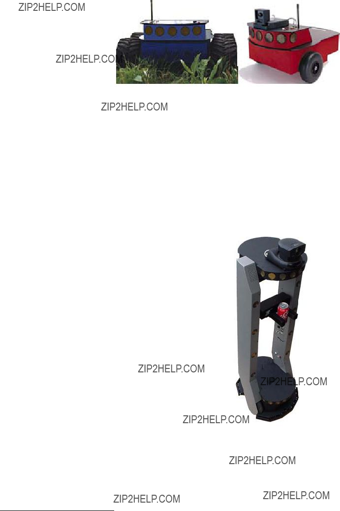
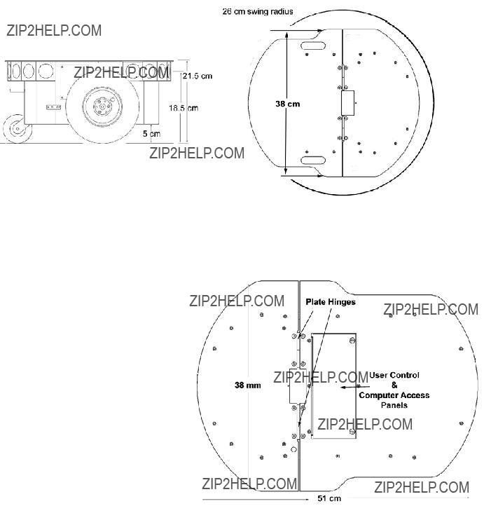
Figure 8. Pioneer
PHYSICAL CHARACTERISTICS
handle.
11

Specifications and Controls
MAIN COMPONENTS
ActivMedia robots are composed of several main parts:
Deck
Motor Stop Button
User Control Panel
Body, Nose, and Accessory Panels
Sonar Array(s)
Motors, Wheels, and Encoders
Batteries and Power
Deck
Figure 10. Components of the Pioneer 3
The original Pioneer
The robot???s deck is simply the flat surface for mounting projects and accessories, such as the PTZ Robotic Camera and the laser range finder.
When mounting accessories, you should try to center the robot's payload over the drive wheels. If you must add a heavy accessory to the edge of the deck, counterbalance the weight with a heavy object on the opposite end. A full complement of batteries helps balance the robot, too.
Motor Stop Button
All new Pioneer
Press the STOP button in to
12

ActivMedia Robotics
User Control Panel
The User Control Panel is where you have access to the
The red PWR LED is lit whenever main power is applied to the robot. The green STAT LED state depends on the operating mode and other conditions. It flashes slowly when the controller is awaiting a connection with a client and flashes quickly when in joydrive mode or when connected with a client and the motors are engaged. It also flashes moderately fast when the controller is in maintenance mode.
The BATTERY LED???s apparent color depends on your robot???s battery voltage: green when fully charged (>12.5 volts) through orange, and finally red when the voltage is below 11.5. When in maintenance mode, however, the BATTERY LED glows bright red only, regardless of battery charge.
A
RADIO and AUX are pushbutton switches which engage or disengage power to the respective devices on the Motor/Power Interface board. See Appendix B for power connections. Respective red LEDs indicate when power is ON.
The red RESET pushbutton acts to unconditionally reset the H8S controller, disabling any active connections or
The white MOTORS pushbutton???s actions depend on the state of the controller. When connected with a client, push it to manually enable and disable the motors, as its label implies. When not connected, press the pushbutton once to enable joydrive mode, and again to enable the motors
13

Specifications and Controls
To engage AROS maintenance mode, press and hold the white MOTORS button, press and release the red RESET button, then release MOTORS. In the future, the white MOTORS button may engage other modes, such as when in AROS standalone mode.
Body, Nose, and Accessory Panels
Your ActivMedia robot???s sturdy, but lightweight aluminum body houses the batteries, drive motors, electronics, and other common components, including the front and rear sonar arrays. The body also has sufficient room, with power and signal connectors, to support a variety of robotics accessories inside, including an A/V wireless surveillance system, radio modems or radio Ethernet, onboard computer, laser range finder, and more.
On all models except the Pioneer
The nose is where we put the onboard PC. The nose is readily removable for access: Simply remove two screws from underneath the front sonar array. A third screw holds the nose to the bottom of the AT???s body. The DX nose is hinged at the bottom.
Once the mounting screws are removed, simply pull the nose away from the body.7 This provides a quick and easy way to get to the accessory boards and disk drive of the onboard PC, as well as to the sonar gain adjustment for the front sonar array. The nose also is an ideal place for you to attach your own custom accessories and sensors.
All DX???s come with a removable
AT???s come with a single access panel in the deck. Fastened down with
All models come with an access port near the center of the deck through which to run cables to the internal components.
7With older Pioneer 2 models, you also needed to remove the Gripper before removing the Nose. With the DXE, and newer DXs and ATs, the Nose and Gripper come off together, so you only need to remove the Nose???s mounting screws.
14
ActivMedia Robotics
Each sonar array comes with its own driver electronics for independent control. Each array???s sonar are multiplexed; the sonar acquisition rate is adjustable, normally set to 25 Hz (40 milliseconds per sonar per array). Sensitivity ranges from ten centimeters (six inches) to over four meters, depending on the ranging rate. You may control the sonar???s firing pattern through software, too; the default is
The driver electronics for each array is calibrated at the factory. However, you may adjust the array???s sensitivity and range to accommodate differing operating environments. The sonar gain control is on the underside of the sonar driver board, which is attached to the floor of each sonar module.
Sonar sensitivity adjustment controls are accessible directly, although you may need to remove the Gripper to access the front sonar, if you have that accessory attached.8 For the front sonar, for instance, locate a hole near the front underside of the array through which you can see the cap of the
Low
Increase the sensitivity of the sonar by turning the
Motors, Wheels, and Position Encoders
Pioneer 2???s and 3???s drive systems use
Inflate the tires evenly
or your robot won???t drive properly.
All Pioneer 3 robots now come with pneumatic tires so that you may configure your robot for differing terrains. In any configuration, however, be careful to inflate the tires evenly and adjust the respective Ticksmm and rotational Revcount FLASH parameters for proper operation. We ship with the tires inflated to 23 psi each.
BATTERIES AND POWER
Except when outfitted with the automated docking/charging system (see below), Pioneer 2 and 3 robots may contain up to three,
8 It???s easier to remove the DXE???s Nose with Gripper attached.
15

Specifications and Controls
and slide each battery out of its bay. Spring contacts on the robot???s battery power board alleviate the need for manually attaching and detaching power cables or connectors.
Balance the batteries in your robot.
Battery life, of course, depends on the configuration of accessories and motor activity. AT charge life typically ranges from two to three hours. The DX runs continuously for six hours or more; up to four hours with onboard computer. If you don???t use the motors, your robot???s microcontroller will run for several days on a single battery charge.
IMPORTANT: Batteries have a significant impact on the balance and operation of your robot. Under most conditions, we recommend operating with three batteries. Otherwise, a single battery should be mounted in the center, or two batteries inserted on each side of the battery container.
Battery Indicators and Low Voltage Conditions
The User Control Panel has a
Aurally, the User Control Panel???s buzzer, if active (see the AROS SoundTog client command and FLASH parameter), will sound a repetitive alarm if the battery voltage drops consistently below the FLASH LowBattery level. If the battery voltage drops below 11 volts, the microcontroller???s watchdog server automatically shuts down a client connection and notifies the computer, via the HOST RI (ring indicator) pin, to shut down and thereby prevent data loss or systems corruption due to low batteries.
Recharging
Typical battery recharge time using the recommended accessory (800 mA) charger varies according to the discharge state; it is roughly equal to three hours per volt per battery. The Power Cube accessory allows simultaneous recharge of three swappable batteries outside the robot.
With the optional
The new automated docking/recharging system is the best option. Because its integrated
All our recommended chargers are specifically designed for safe
16
ActivMedia Robotics
DOCKING/CHARGING SYSTEM
The Pioneer 3/PeopleBot docking/charging accessory is both a manual and an automated mechanism. Onboard controls, triggered either by the DEPLOY CHARGER button near the manual CHARGE port, or by H8S
While connected, onboard circuitry conditions the power to optimally charge the three
The charging mechanism and onboard power conditioning circuitry can be retrofitted to all Pioneer 3 and some Pioneer 2 and PeopleBot robots; all require return to the factory.
Manual Operation (Robot Power OFF)
With MAIN POWER off, place the robot over the charge platform so that its charging contacts are perpendicular to and, when deployed, contact the charger plates. Note that no charging power is applied to the plates on the platform; only low signal (5VDC @ <300mA) power for the IR detectors.
Press and hold the DEPLOY CHARGER button to manually deploy the charge mechanism on the bottom of the robot. Hold for a few seconds, but not more than 10 seconds. Charging is activated by positive contact with the charging platform. In that case, the charge lamp on the charger unit will light and the robot's contacts will remain deployed when you release the DEPLOY CHARGER button. Otherwise, the mechanism will retract. In that case,
The robot's charging mechanism automatically retracts if you press the DEPLOY CHARGER button while charging, if you move the robot on the docking platform and lose positive charging contact, or if you remove power from the charger unit. In all cases, charging power is removed immediately from the docking platform when not actively engaged by the robot.
Manual Operation (Robot Power and Systems ON)
Because the automated docking/charging system???s charger and integrated circuitry actively adjusts to system loads, it can run your robot's onboard systems while properly and optimally recharging its batteries. And because the charging mechanism may be operated independently of your robot's systems power, you may start up and shut down your robot and its onboard systems without disturbing the battery charging cycle, if engaged.
For example, with MAIN POWER on, use joystick mode to position the robot onto the charging platform. Then reset the robot controller and manually deploy the charging mechanism as described in the section above. Thereafter, switch MAIN POWER off, or conversely, start up and shut down other onboard systems, including the PC, camera, laser, and other accessories, to proceed with development work without disturbing battery recharging.
The same conditions apply to remove charging power and retract the robot's charging mechanism with the robot???s MAIN POWER on as well as off. In addition, engaging the motors, such as when you press the white MOTORS button on the robot controller to engage
17

Specifications and Controls
mechanism. And the charging mechanism will not activate until you disengage the motors, either manually or programmatically.
RADIO CONTROLS AND ACCESSORIES
All ActivMedia robots are servers in a
For the piggyback laptop or embedded PC, that serial connection is a cable. Radio modems simply replace that serial cable with a wireless tether. Accordingly, if you have radio modems, one is inside your robot and connected to the controller???s HOST serial port, and the other modem plugs into a serial port on some offboard computer where you run your client software. Hence, in these configurations, there is one dedicated client computer. (See Appendix C for radio modem settings.)
Figure 13.
Radio Ethernet is a little more complicated because it lets you use many different computers on the network to become the robot???s client. A special onboard Serial- Ethernet accessory that we provide is a standard wireless Ethernet radio which connects to your local TCP/IP network through an Access Point. But it???s different from most standard wireless Ethernet devices in that it also connects to the HOST serial port on the robot???s microcontroller. It works by automatically translating
A major disadvantage of the wireless
This is why we recommend onboard client PCs for wider, much more robust areas of autonomous operation, particularly when equipped with their own wireless Ethernet. In this configuration, you run the client software and its interactions with the robot controller locally and simply rely on the wireless connection to export and operate the client controls, such as through
18

ActivMedia Robotics
ONBOARD PC
Unlike the original Pioneer 1, Pioneer 2 and 3 robots are designed to support an onboard, internally integrated PC for fully autonomous operation. Mounted just behind the nose of the robot, the PC is a common EBX
Necessary 5 VDC power comes from a dedicated DC:DC converter, mounted nearby. A
The onboard PC communicates with the H8S microcontroller through its HOST serial port and the dedicated serial port COM1 under Windows or /dev/ttyS0 on Linux systems. Automatic systems on the microcontroller switch in that
Note also that some signals on the H8S microcontroller???s HOST serial port as connected with the onboard PC or other accessory can be used for
automated PC shutdown or other utilities: Pin 4 (DSR) normally is RS232 high when the controller operates normally; otherwise it is low when reset or in maintenance mode. Similarly, pin 9 (RI) normally is low and goes
Computer Control Panel
Figure 15. AT computer and user controls
19
Specifications and Controls
The controls and ports use common connectors: standard monitor DSUB and PS/2 connectors on the mouse and keyboard. The Ethernet is a
The ON/OFF slide switch directly controls power to the onboard
The HDD LED lights when the onboard
Operating the Onboard PC
This is a brief overview of operating the onboard PC. Please consult the Computer Systems Documentation and the OS manufacturer???s documentation for more detail. ActivMedia Robotics??? software runs over either Microsoft Windows (currently Windows 2000??) or RedHat?? Linux (currently version 7). Accordingly, we prefer (the latter, in particular) and support those OSes on the onboard PC.
When we perform the installation and configuration, we install our robotics and accessory software typically in /usr/local on Linux systems, or in C:\Program Files\ActivMedia Robotics under Windows. Of course, we install the appropriate drivers for the various accessory expansion cards, such as for a framegrabber or sound card. Please consult the respective ActivMedia Robotics application software manuals, such as the ActivMedia Color Tracking System (ACTS) for the video framegrabber or Festival for the sound card.
The first time you access the onboard PC, we recommend that you put the robot up on blocks so that it cannot inadvertently move and wreak havoc with external connections. Then attach a keyboard, monitor, and mouse to their respective sockets on the Computer Control Panel. Switch Main Power and then the computer power switch on.
After boot up, log in to the system. We???ve already created two users: one with common systems and file read/write permissions (guest) and one with
Once logged into a Windows system, it???s simply a matter of clicking the mouse to select programs and applications. With Linux, use the ???startx??? command to enable the X- Windows desktop and GUI environment. You might perform some of the QuickStart activities this way, although motion is impractical because of the monitor, mouse, and keyboard tethers. You may remove these while the system is active at your own risk.
Rather, we suggest that you run the QuickStart activities from an offboard computer first (onboard PC off), and then tackle the networking issues to establish a remote, preferably wireless connection with your robot.
PC Networking
The
20

ActivMedia Robotics
To complete the wireless installation, you will need to provide an Access Point module (comes as an accessory with most units). Attach the Access Point to one of your LAN hubs or switches with a standard CAT5
We ship installed PC systems??? preset and tested at a fixed IP address with
Briefly, with Windows, go to the Control Panel???s Network and Dialup Connections wizard and choose the networking device???s Properties to change the IP address and other details. Under Linux, there are similar,
From Windows, use the Control Panel Network and Dialup Connections tool to enable or disable a particular device. From Linux, use ifup and ifdown to enable or disable an Ethernet device. For example, as superuser, type ???ifdown eth0; ifup eth1??? to switch from a tethered to a wireless Ethernet connection.
For remote connections over Ethernet to your onboard PC, simply use telnet or the more secure ssh to log in to your Linux system. Allow
With Windows, you will need a special
VNCserver, for example, or XWin32.
Please note that you may not connect with the robot???s microcontroller directly over the network: That is, you cannot run a client application, such as the ARIA demo or Saphira, on the remote PC and choose to directly connect with the robot server by selecting the robot PC???s IP address. Rather, either run the client application on the onboard PC and export the display and controls over the network to the remote PC (preferred), or use the
UPS and Genpowerd
To protect your robot???s onboard PC data, we???ve enabled a detection scheme in AROS and
AROS versions 1.6 and later raises the HOST serial port's RI pin 9 to
9 The original Pioneer 2
21

Specifications and Controls
below safe operating level of ~11 VDC.10,11 Genpowerd running on the onboard Linux system or ups.exe running under Windows, detects the change of state and initiates OS shutdown after a short wait, during which the shutdown may be canceled by raising the battery voltage, such as by attaching a charger.
Genpowerd monitors the HOST serial RI port on /dev/ttyS0. Windows??? ups.exe requires a dedicated serial
SAFETY AROS WATCHDOGS
AROS contains a communications watchdog that will halt the robot???s motion if communications between a PC client and the robot server are disrupted for a set time interval, nominally two seconds (watchdog parameter). The robot will automatically resume activity, including motion, as soon as communications are restored.
AROS also contains a stall monitor. If the drive exerts a PWM pulse that equals or exceeds a configurable level and the wheels fail to turn (stallval), motor power is cut off for a configurable amount of time (stallwait). The server software also notifies the client which motor is stalled. When the stallwait time elapses, motor power automatically switches back on and motion continues under server control.
There also is the LowBattery FLASH parameter that sets off an audible warning when the batteries fall below a safe charge level. To avoid systems corruptions, the AROS servers force a soft system shutdown, possibly including the onboard PC (Linux genpowerd or Windows??? ups.exe), when the batteries fall below approximately 11 volts.
All these ???failsafe??? mechanisms help ensure that your robot will not cause damage or be damaged during operation. You may reconfigure the various
10RI and DSR on the HOST serial port are RS232 low during reset or when the controller is in Maintenance Mode.
11AROS versions 1.5 and earlier raised the HOST serial port's DSR and RI to
22

ActivMedia Robotics
Chapter 4 Quick Start
This chapter describes how to quickly set up and operate your new ActivMedia robot with the ARIA demonstration software. For more details about programming and operating your ActivMedia mobile robot with ARIA, Saphira, or other client software, see their respective programming manuals.
PREPARATIVE ASSEMBLY
Your ActivMedia robot comes fully assembled and ready for
If you have the onboard PC option, we recommend that you leave it off and perform the following tests first with a laptop or desktop computer tethered to the robot???s serial port on the User Control Panel, then attack the many networking issues before you establish a
Install ARIA
The ARIA client
ActivMedia Robotics customers also may obtain ARIA and related software and updates from our support website:
http://robots.activmedia.com
When installed, ARIA typically requires ten or more megabytes of
The Windows version of ARIA is a
into a directory named C:\Program Files\ActivMedia Robotics\ARIA. The demonstration program and simulator get put into the bin\ subdirectory. For convenience, you may access all these from the Start Menu???s Programs option. The demonstration program???s source code and MSVC++ project and workspace files are in the examples\ subdirectory.
Linux users must have superuser (root) permissions in order to install ARIA. It comes as an RPM installation archive:
rpm
and gets installed in /usr/local/Aria. The ARIA demonstration program and simulator get put into the bin/ subdirectory. The demonstration sources and makefile are in the examples/ subdirectory.
Linux users should also be sure they have permission to read/write through their PC???s serial port that connects with the robot. The default is /dev/ttyS0. ARIA is a terminal application that does not include a GUI, so its programs do not require
CAREFUL
Slide the batteries into the robot TERMINALS LAST.
Otherwise, you will damage the robot.
23

Quick Start
Install Batteries
Out of the box, your ActivMedia robot comes with its batteries fully charged, although shipped separately, unless you have the automated docking/charging system. For most models, slide one or up to three batteries into robot???s battery box through the back door. Balance them: one in the center; if two, then one on each side.
Your robot requires a serial communication link with a client PC for operation. The serial link may be:
A tether cable from the robot???s
A piggyback laptop cabled to the User Control Panel Serial Ethernet
Radio Modem
An integrated onboard PC wired internally for direct onboard control
STARTING UP CLIENT AND SERVER
We recommend that you first test your robot and are confident of its operation before putting it together with and controlling it from the ARIA demonstration client.
Drive
Position your ActivMedia robot on the floor or ground in an open space, or up on blocks if you have attachments to the Computer Control Panel. Slide the Main Power switch to ON. You should hear an audible beep, and the Power light and Battery light should glow while the Status light blinks rhythmically on the User Control Panel. The same AROS initialization sequence also occurs whenever you press the red RESET button.
Now press the white MOTORS button twice to engage the motor???s
Press the red RESET button to prepare for the client connection.
Client Server Connection
ARIA???s examples are
First, please note well that you cannot connect with and control your ActivMedia robot through its controller directly from a remote client over the network without special hardware (new radio
To start the ARIA client demonstration program and connect with the robot, we presume that you have completed the preparatory stages of this chapter by installing ARIA (as
12Look in the ARIA/examples directory for a program called ipthru. It converts IP to serial and back again for
24
ActivMedia Robotics
needed), by starting and testing the robot, and by connecting the client PC with the AROS controller via a serial link. Now it is time to connect the ARIA demonstration program with your robot.
If you are using radio modems or the new
Windows users may select the ARIA demo from the Start menu, in the ActivMedia Robotics program group. Otherwise, start if from the ARIA bin\ directory.
Linux users will find the compiled demo in /usr/local/Aria/bin/ or in examples/. Start it:
% ./demo
Demo Startup Options
Table 1. ARIA demo command line arguments
By default, the ARIA demo program connects with the robot through the serial port COM1 under Windows or /dev/ttyS0 under Linux. And, by default, the demo connects with the laser rangefinder accessory through serial port COM3 or /dev/ttyS2. To change those connection options, either modify the ARIA source code (examples/demo.cpp and related files in src/) and recompile the demo application, or use a startup argument on the command line. See Table 1.
For example, from the Windows Start:Run dialog, choose Browse??? and select the ARIA
demo program: C:\Program Files\ActivMedia Robotics\ARIA\bin\demo.exe.
Then, type a command line argument at the end of the text in the Run dialog as described in Table 1. To connect through the new
C:\Program Files\ActivMedia Robotics\ARIA\bin\demo.exe
25

Quick Start
A Successful Connection
ARIA prints out lots of diagnostic text as it negotiates a connection with the robot. If successful, the client requests various AROS servers to start their activities, including sonar polling, position integration, and
so on. The microcontroller sounds an audible connection
When connected with the ARIA demo client, your robot becomes responsive and intelligent. For example, it moves cautiously. Although it may drive toward an obstacle, your ActivMedia robot will not crash because the ARIA demo includes obstacle- avoidance behaviors which enable the robot to detect and actively avoid collisions.
direction incrementally. For instance, when turning, it is often useful to press the left- or
The other modes of ARIA demo operation give you access to your robot???s various sensors and accessories, including encoders, sonar, laser, Gripper, a
26

ActivMedia Robotics
as a demonstration tool, but as a diagnostic one, as well, if you suspect a sensor or effector has failed or is working poorly.
Access each ARIA demo mode by pressing its related
DISCONNECTING
When you finish, press the Esc key to disconnect the ARIA client from your robot server and exit the ARIA demonstration program. Your ActivMedia robot should disengage its drive motors and stop moving, and its sonar should stop firing. You may now slide the robot???s Main Power switch to OFF.
QUICKSTART TROUBLESHOOTING
Most problems occur when attempting to connect the ARIA client with a robot for the first time. The process can be daunting if you don???t make the right connections and installations.
ATTENTION!
The
Proper Connections
Make sure you have ARIA properly installed and that your robot and connections are correct. A common mistake with Linux is not having the proper permissions on the connecting serial port.
Make sure your robot???s batteries are fully charged (battery LED green). The robot servers shut down and won???t allow a connection at under 10.5 volts.
If you are using the onboard PC or radios, the serial connection is internal and established at the factory; you should not have problems with those cables. Simply make sure the RADIO switch is ON, for example. And remove any serial cable that is plugged into the User Control Panel as it may interfere with internal serial communication.
With other serial connections, make sure to use the proper cable: a
If you access the wrong serial port, the ARIA demonstration program will display an error message. If the robot server isn't listening, or if the serial link is severed somewhere between the client and server (cable loose or the radio is off, for instance), the client will attempt "Syncing 0" several times and fail. In that case, RESET the robot and check your serial connections. For instance, if you are using radio modems, the DCD lamp on the HOST unit next to your PC should light up. If it doesn't, it means it cannot find the one in the robot.
If for some reason communications get severed between the ARIA client and AROS server, but both the client and server remain active, you may revive the connection with little effort: If you are using radio modems, first check and see if the robot is out of range.
27
Quick Start
To test for range limits, simply pick up the robot and move it closer to the basestation radio modem or access point. If the robot was out of range, the connection should resume. If not, check to make sure that radio modems were not inadvertently switched
OFF.
Communications also will fail if the client and/or server is somehow disabled during a session. For instance, if you inadvertently switch off the robot???s Main Power or press the RESET button, you must restart the connection. Turning the Main Power switch OFF and then back ON, or pressing the RESET button puts the robot servers back to their wait state, ready to accept client connections again. If the ARIA demo or other client application is still active, simply press esc and restart.
SRIsim
To verify proper installation of the software, you might run the robot simulator, SRISim. It is in the same directory as the ARIA demonstration program. Start SRIsim first, then the ARIA demo program. ARIA should successfully connect with the simulator if the software has been installed correctly.
SRIsim looks like a real robot to the ARIA client, so you can operate the demo as you do your own ActivMedia robot. SRIsim includes simulated worlds and different robot profiles which you select from the Files menu, too, so you can see how different robots might navigate in a real or imagined space.
28

ActivMedia Robotics
Chapter 5 Joydrive and
Although not all models come standard with a joystick port, your robot???s
To run in either joydrive or
You may also enable AROS??? joydrive server while connected with a client by sending the client command number 47 with the integer argument 1.
JOYDRIVE MODE
To joydrive your robot when not connected with a client program, switch the robot???s Main Power ON or RESET the controller, then press the white MOTORS button on the User Control Panel once. Listen for a rhythmic,
To joydrive your robot while it is connected with a client (overrides
The joystick is
The joystick???s fire button 1 acts as the joydrive
When not connected with a client control program, releasing the joystick fire button stops the robot. However when connected with a client, the client program resumes automatic operation of your robot???s drive system. So, for example, your robot may speed up or slow down and turn, depending on the actions of your client program.
You may adjust the maximum translational and rotational speeds and even disable joydrive mode, through special AROS FLASH configuration parameters. See Chapter 7,
Updating & Reconfiguring AROS, for details.
13The joystick adaptor kit, including the
29

Joydrive and Self Tests
ENGAGING
To enable
ATTENTION!
Place your robot on the floor or ground and have everyone step back before engaging
Currently, the only AROS
The motor???s
The
14 As described above, the first MOTORS press and release puts the robot into joydrive mode.
30

ActivMedia Robotics
Chapter 6 ActivMedia Robotics Operating System
All ActivMedia robots use a
With this client/server architecture, robotics applications developers do not need to know many details about a particular robot server, because the client insulates them from this lowest level of control. Some of you, however, may want to write your own robotics control and reactive planning programs, or just would like to have a closer programming relationship with your robot. This chapter explains how to communicate with and control your ActivMedia robot via the ActivMedia Robotics Operating System (AROS)
Figure 16. ActivMedia Robotics
Experienced ActivMedia robot users can be assured that AROS is upwardly compatible with all ActivMedia robots, implementing the same commands and information packets that first appeared in the Pioneer
ActivMedia robots communicate with a control client using special
The two byte header which signals the start of a packet is the same for both client- command packets and SIPs: 0xFA, 0xFB. The byte count value counts the number of all subsequent bytes in the packet including the checksum, but not including the byte count value itself or the header bytes.
Data types are simple and depend on the element (see descriptions below): client commands, SIP types, and so on, are single
31

ActivMedia Robotics Operating System
always first. Some data are strings of up to a maximum 200 bytes, prefaced by a length byte. Unlike common data integers, the
Packet Checksum
Calculate the PSOS/P2OS/AROS
int calc_chksum(unsigned char *ptr)
{
//ptr is array of bytes
//first is data count
int n; int c = 0;
c += (*(ptr)<<8) | *(ptr+1); c = c & 0xffff;
n
}
if (n > 0)
c = c ^ (int)*(ptr++); return(c);
}
NOTE: The checksum integer is placed at the end of the packet, with its bytes in the reverse order of that used for data integers; that is, b0 is the high byte and b1 is the low byte.
Packet Errors
AROS ignores a client command packet whose byte count exceeds 204 (total packet size of 206 bytes) or has an erroneous checksum. The client should similarly ignore erroneous SIPs.
AROS does not acknowledge receipt of a command packet nor does it have any facility to handle client acknowledgment of a SIP. Accordingly, when designing client applications, keep in mind serial communication limitations, particularly data rates and physical linkage. Communication between an onboard PC client connected with the server via a signal cable is much more reliable than over radios, for example. And don???t expect to send a client command every millisecond if the HOST serial port???s baud rate is set to 9,600 kbps.
Because of the
Nonetheless, the
32

ActivMedia Robotics
SERVER INFORMATION PACKETS
Like its PSOS and P2OS predecessors, AROS automatically and repeatedly sends a packet of information over its HOST serial port to a connected client. The standard AROS SIP informs the client about a number of operating states and readings, using the order and data types described in the nearby Table.
Table 3. Standard Server Information Packet
???
AROS also supports several additional SIP types. These include an ???alternative??? SIP that currently is not supported by Saphira or ARIA.15 See following sections in this chapter for a description of the extended SIP types.
15 Indeed, if enabled, the alternative SIP apparently will ???break??? the client software. Read carefully.
33

ActivMedia Robotics Operating System
CLIENT COMMANDS
AROS has a structured command format for receiving and responding to directions from a client for control and operation of your ActivMedia robot or the simulator. Client commands are comprised of a
Table 4. AROS/P2OS/PSOS client command packet protocol
Table 5. AROS/P2OS/PSOS command set
34
ActivMedia Robotics
16 No, this isn???t a
35

ActivMedia Robotics Operating System
The number of client commands you may send per second depends on the HOST serial baud rate, average number of data bytes per command, synchronicity of the communication link, and so on. AROS??? command processor runs on a one millisecond interrupt cycle, but the server response speed depends on the command. Typically, limit client commands to a maximum of one every
THE
Before exerting any control, a client application must first establish a connection with the robot server via a serial link through the robot controller???s HOST port. After establishing the communication link, the client then sends commands to and receives operating information from the server.
When first started or reset, AROS is in a special wait state, listening for communication packets to establish a
Specifically, and as examples of the client command protocol, the synchronization sequence of bytes is (in hexadecimal notation):
SYNC0: 0xFA, 0xFB, 0x03, 0x00, 0x00, 0x00
SYNC1: 0xFA, 0xFB, 0x03, 0x01, 0x00, 0x01
SYNC2: 0xFA, 0xFB, 0x03, 0x02, 0x00, 0x02
When in wait mode, AROS echoes the packets verbatim back to the client. The client should listen for the returned packets and only issue the next synchronization packet after it has received the appropriate echo.
17 There also is monitor mode for AROS downloads and parameter updates; see next chapter for details.
36

ActivMedia Robotics
Autoconfiguration (SYNC2)
AROS automatically sends robot configuration information back to the client following the last synchronization packet (SYNC2). The configuration values are three NULL- terminated strings that comprise the robot???s
The class string typically is Pioneer. The subclass depends on your robot model; P2D8 or P2AT8, for example. Clients may use these identifying strings to
Opening the
Once you???ve established a connection with AROS, your client should send the OPEN command #1 (no argument; 0xFA, 0xFB, 0x03, 0x01, 0x00, 0x01) to the server, which causes the ActivMedia robot controller to perform a few housekeeping functions, start its various servers, such as for the sonar and motor controllers, listen for client commands, and begin transmitting server information to the client.
Note that once connected, your robot's motors are disabled, regardless of their state when last connected. To enable the motors after starting a connection, you must either do it manually (press the black MOTORS/TEST button) or have your client send an ENABLE client command #4 with an integer argument of 1 (0xFA, 0xFB, 0x06, 0x04, 0x3B, 0x01, 0x00, 0x05, 0x3B).
Keeping the
A safety watchdog expects that, once connected, your robot???s controller receives at least one communication packet from the client every watchdog seconds (default is two). Otherwise, it assumes the
Some
If the robot shuts down due to lack of communication with the client, it will revive upon receipt of a client command and automatically accelerate to the
Closing the
To close the
Once connected, send the ENABLE command
or press the white MOTORS button on the User Control Panel to enable your robot???s motors.
37

ActivMedia Robotics Operating System
With AROS versions 1.3 and later, many of the controller???s operating parameters return to their
MOTION COMMANDS
The AROS
Note that once connected, ActivMedia robots??? motors are disabled, regardless of their state when last connected. Accordingly, you must either enable the motors manually (white MOTORS button on the User Control Panel) or send the motors ENABLE client command #4 with the argument value of one.19 Monitor the status of the motors with bit 0 of the Flags integer in the standard SIP.
When in
Table 6. AROS motion commands
Rotation
HEAD (#12) Turn to absolute heading at SETRV max velocity
DHEAD (#13), Turn to heading relative to control point at SETRV max velocity
DCHEAD (#22)
ROTATE (#9) Rotate at SETRV velocity
Translation
VEL (#11) Translate forward/reverse at prescribed velocity (SETV maximum)
MOVE (#8) Translate distance at SETV max velocity
Independent Wheel
VEL2 (#32) Set velocity for each side of robot (SETV maximum)
18With earlier versions, the changes persisted between sessions, and reverted to the FLASH defaults only after the controller was reset.
19Alternatively, disable the motors with the ENABLE command argument of zero.
38
ActivMedia Robotics
ActivMedia Robots in Motion
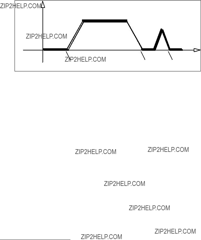
ActivMedia robots use position, as opposed to velocity, motion controls to translate the platform a certain distance and turn it to a particular heading. To achieve constant translational (VEL), rotational (ROTATE), or
When the robot controller receives a motion command, it accelerates or decelerates the robot at the translational SETA (#5) (TR and VEL2 modes) and rotational SETRA (#23; TR mode only) rates until the platform either achieves its SETV (#6) maximum translational and SETRV (#10) maximum rotational speeds, or nears its goal. Accordingly, rotational headings and translational setpoints are achieved by a trapezoidal velocity function, which AROS recomputes each time a new motion command is received.20
Figure 17. ActivMedia robot???s trapezoidal velocity profile
AROS automatically limits
Note that the E_STOP command #55 or the STOP button that is found on some ActivMedia robots override deceleration and immediately stop the robot in the shortest distance and time possible. Accordingly, the robot brakes to zero translational and rotational velocities with very high deceleration and remains stopped until it receives a subsequent translational or rotational velocity command from the client or until the STOP button is reset. (See E_STOP and E_STALL later in this chapter.)
Platform Dependent and Independent Variables
All
20Note that acceleration and deceleration are distinct values, settable via SETA for translation and SETRA for rotation.
39

ActivMedia Robotics Operating System
At the same time, AROS reports back to the client in the standard SIP the robot???s position and speed. Not all robots convert these values into
So when you tell the robot to move a certain number of millimeters forward, measure its actual travel with a meter tape and adjust ticksmm accordingly. Similarly, turn the robot and adjust revcount to achieve the correct heading.
Then, when you are satisfied that the robot moves and turns precisely, adjust the various parameter
Please see the next chapter for a detailed description of these
PID Controls
The AROS drive servers use a common
The AROS drive servers recalculate and adjust your robot???s trajectory and speed every five milliseconds based on feedback from the wheel encoders.
work best with Kp in the range of 20 to 30.
The D term Kv provides a PID gain factor that is proportional to the output velocity. It has the greatest effect on system damping and minimizing oscillations within the drive system. The term usually is the first to be adjusted if you encounter unsatisfactory drive response. Typically, we find Kv to work best in the range of 600 to 800 for lightly to heavily loaded robots, respectively.
The I Term Ki moderates any steady state errors thereby limiting velocity fluctuations during the course of a move. At rest, your robot will seek to ???zero out??? any command position error. Too large of a Ki factor will cause an excessive windup of the motor when the load changes, such as when climbing over a bump or accelerating to a new speed.
40
ActivMedia Robotics
Consequently, we typically use a minimum value for Ki in the range of 0 to 10 for lightly to heavily loaded robots respectively.
Position Integration
ActivMedia robots, including Pioneer 2s and 3s, track their position and orientation based on
Be aware that with the simulator as well as with real robots, registration between external and internal coordinates deteriorates rapidly with movement, due to gearbox play, wheel imbalance and slippage, and many other
Also, moving either too fast or too slow tends to exacerbate the absolute position errors. Accordingly, consider the robot???s
The orientation commands HEAD and DHEAD turn the robot with respect to its internal
You may reset the internal coordinates to 0,0,0 with the SETO command #7.
SONAR
When connected with and opened by the client, AROS automatically begins firing your robot???s sonar, one disc each simultaneously for each array, as initially sequenced and enabled in your robot???s FLASH parameters. The sonar servers also begin sending the
Enable/Disabling Sonar
Use the SONAR client command #28 to enable or disable all or individual sonar arrays. Set ("1") bit zero of the SONAR argument to enable or reset it ("0") to disable the sonar pinging. Set argument bits two through four to an individual array number one through four to enable or disable only that array. Array zero, the form of the P2OS command, affects all the arrays at once.
For example, an argument value of one enables all the sonar arrays, whereas an argument value of six silences array number three. Monitor the status of the sonar arrays in the FLAGS integer of the standard SIP.
Polling Sequence and Rate
Each array???s sonar fire at a rate and in the sequence defined in your robot???s FLASH parameters. (Consult the next chapter on how to change the FLASH settings.) Use the sonar POLLING command #3 to have your client change the firing sequence, and the SONAR_CYCLE command #48 to change the rate. The changes persist until you reset the controller or restart the
The POLLING command string argument consists of a sequence of sonar numbers one through 32. Sonar numbers one through eight get added to the polling sequence for
41

ActivMedia Robotics Operating System
sonar array number one; numbers nine through 16 get added to the sequence for sonar array number two;
Note that for compatibility with earlier ActivMedia robot operating systems, if the string is empty, all the sonar get disabled, but their polling sequences remain unaltered, just as if you had sent the SONAR command with an argument value of zero.
In earlier versions of AROS and P2OS, the sonar polling rate is fixed: one sonar per array gets polled every 40 milliseconds. That common cycle timing accommodates ranging out to the maximum of the sonar of several meters for general applications, including features recognition and localization. For other applications, such as
Hence, we introduce in AROS v1.8 the SonarCycle FLASH parameter which lets you set, through AROScf, the default sonar cycle time, in milliseconds. Use the SONAR_CYCLE client command #48 to change the cycle timing on the fly to the command integer's argument value in milliseconds.
STALLS AND EMERGENCIES
With a robot equipped with forward and/or rear bumpers, by default AROS immediately stops the robot and notifies the client of a stall if any one or more of the contact sensors get triggered and the robot is going in the direction of the bump (forward/front or backward/rear). Send the BUMPSTALL command #44 with an integer argument of zero to disable that
Change AROS???
In an emergency, your client may want the robot to stop quickly, not subject to normal deceleration. In that case, send the
E_STOP command (#55).
Like BUMPSTALL, use AROS???
Unlike other stalls, E_STALL also disables the motors. You must either
The E_STALL server notifies your client software through the stall bytes and in bit 5 of the FLAGS byte in the standard so that your client may respond to a STOP E_STALL differently than a regular stall.
21 Available only on some robots.
42

ActivMedia Robotics
Normally enabled (default was disabled in P2OS), change E_STALL by sending the AROS command #56. With argument of zero, E_STALL gets disabled. An argument value of one
ACCESSORY COMMANDS AND PACKETS
Several types of alternative server information packets (SIPs) come with AROS to better support the ActivMedia Robotics community. On request from the client by a related AROS command, the AROS server packages and sends one or a continuous stream of information packets to the client over the HOST serial communication line. Extended packets get sent immediately after the standard SIP that AROS sends to your client every SIP milliseconds (typically 100).22
The standard SIP takes priority and gets sent as soon as the communication port is free and the cycle timer expires. So you may have to adjust the communications baud rate to accommodate all data packets in the allotted cycle time, or some packets may never get sent.
Packet Processing
Identical with the standard SIP, all AROS server information packets get encapsulated with a header (0xFA, 0xFB), byte count, packet type byte, and trailing checksum. It is up to the client to parse the packets, sorted by type for content. Please consult the respective client application programming manuals for details.
ARIA, for example, comes with a framework for packet parsing and has an internal parser for the PSOS/P2OS/AROS packet type 0x3S
Table 8. CONFIGpac contents (AROS v1.5 and later)
22 You may have to adjust the HOST serial baud rate to accommodate the additional communications traffic.
43
ActivMedia Robotics Operating System
CONFIGpac and CONFIG Command
Send the CONFIG command #18 without an argument to have AROS send back a CONFIGpac SIP packet type 32 (0x20) server information packet containing the robot's operational parameters. Use the CONFIGpac to examine many of your robot???s default FLASH_based settings or their working values, when appropriate, as changed by other client commands, such as SETV and ROTKV. A table nearby gives details about the configuration packet data.
SERIAL PORT COMMUNICATIONS
AROS provides
Changing Baud Rates and Autobauding
The baud rates for the HOST, AUX1, and AUX2 ports initially are set from their respective
44
ActivMedia Robotics
For
Use the
AROS also maintains two circular buffers for incoming serial data from the AUX1 and AUX2 ports. On request, AROS sends successive portions of the buffers to your client via the HOST port in the respective SERAUXpac (type = 176; 0xB0) and SERAUX2pac (type = 184; 0xB8) SIPs. Use the GETAUX command 43 for AUX1 or GETAUX2 command number 67 for AUX2. Use the integer argument value of zero to flush the contents of the respective buffer. Use an argument value of up to 253 bytes to have AROS wait to collect the requested number of incoming
ENCODER PACKETS
Issue the ENCODER command #19 with an argument of one for a single, or with an argument value of two or more for a continuous stream of ENCODERpac (type 144; 0x90) SIPs. Discontinue the packets with the ENCODER command #19 with an argument of zero.
Table 9. ENCODERpac SIP contents
Gripper packets
AROS controls the Gripper accessory for the Pioneer and Performance PeopleBot robots. The client sends commands to the Gripper servers and gets Gripper status information from the standard SIP. Please consult the respective manuals for details.
Table 10. GRIPPERpac packet contents
AROS supports a GRIPPERpac (type=224; 0xE0) packet type and related GRIPREQUEST P2OS command #37 to retrieve setup and status information from the servers.
Normally disabled, your client program may request one or a continuous stream (command argument > one) of Gripper packets. Send GRIPREQUEST with the argument value zero to stop continuous packets.
45
ActivMedia Robotics Operating System
Table 11. GRIPPERpac state byte
Note that the Gripper status information bits
Sounds
Unlike its ActivMedia robot cousins, the AmigoBot mobile robot has onboard sound reproduction hardware and software that includes a playlist of contents. To support the ActivMedia Robotics Interface for Applications (ARIA) that includes all ActivMedia???s robots, we???ve included the PLAYLISTpac (type = 208; 0xD0) and PLAYLIST request command 91 in AROS. We document the command and packet here for completeness, but they have no effect on the operation or performance of your ActivMedia mobile robot.
The AmigoBot sounds playlist consists of a series of one to 255
Sound references consist of a
Whereas the AmigoBot has a
The SAY command number 15 lets you play your own sounds through the buzzer. The argument consists of a
\012\001\012\000\012\010\012\000\012\001
TCM2
The TCM2 accessory is an integrated inclinometer, magnetometer, thermometer, and compass that attaches to one of the AUX serial ports of the AROS microcontroller. When attached and enabled, special TCM2 compass servers read and report the heading as the compass byte in the standard SIP. Use the TCM2 command 45 to request additional information from the device in the form of the TCM2pac. See the TCM2 Manual and supporting software that accompanies the device for details.
46
ActivMedia Robotics
Onboard PC
Communication between the onboard PC and the H8S microcontroller is RS232 serial through the respective COM1 (Windows) or /dev/ttyS0 (Linux) and internal HOST ports. Set the HostBaud FLASH communication rate to match the PC
Beginning with AROS version 1.6, the RI pin 9 on the HOST port initializes to low and goes high when the batteries discharge to below 11 VDC. We use the genpowerd software under Linux to detect that
The Windows
Once the port is wired, start up Windows and, as Administrator, go to the
Start:Settings:Control Panel:Power Options dialog and select the UPS tab. Click
Select and in the UPS Selection dialog, select COM2 (or other) port, Generic manufacturer, and Custom model. Then click Next.
In the UPS Interface Configuration On: COM2 dialog, check the Power Fail/On Battery and its related Position options. Uncheck to disable the Low Battery and UPS Shutdown options. Then click Finish to save the settings and close the dialog. Click OK or Apply to enable the UPS shutdown programs.
Change a registry value so that the PC shuts down one minute instead of two minutes after
[HKEY_LOCAL_MACHINE\SYSTEM\ControlSet001\Services\UPS\Config. Change the ShutdownOnBatteryWait dword value to 1 (from 2).
Use the AROS client maintenance command #250 to test your genpowerd or ups.exe setup. Send the COMshutdown command #250 with an integer argument of 1 to simulate the low battery condition, in which AROS issues warnings first, then disconnects from the client after about a minute and sets the
Put the controller into maintenance mode and fix your onboard PC settings if the computer falsely engages genpowerd or ups.exe.
Heading Correction Gyro
With the new
AROS collects
47

ActivMedia Robotics Operating System
modifications to the robot's heading are done on the client side, as supported in the latest versions (1.3 and later) of ARIA.
To enable the gyro, you must set the HasGyro FLASH parameter to 1 using the AROScf tool (see next chapter). Set it to 0 if the gyro isn't attached. Then to acquire gyro data, send the GYRO client command #58 with integer argument of one; zero disables the gyro SIP. The gyro SIP is stopped upon client disconnection or controller reset, too.
AROS collects the gyro rate and temperature readings at the maximum rate of once every 25 milliseconds and reports each of these values to the client, when enabled, in the GYROpac SIP that gets sent just before the standard Server Information Packet every sInfoCycle, typically every 100ms. GYROpac consists of a count byte of the rate and temperature data pairs accumulated since the last cycle (typically 4 for a 100ms cycle time), followed by that number of rate/temperature integer/byte pairs.
Gyro rates are
Table 12. GYROpac SIP contents
INPUT OUTPUT (I/O)
Your
User I/O
The User I/O connector on the H8S controller contains eight digital input and eight digital output ports, as well as an
Use the AROS client command number 30 to set one or more of the eight DIGOUT ports on the AROS controller. Electrically, the ports are digital high (1) at ~5 VDC (Vcc) and low
(0) at ~0 VDC (GND). DIGOUT uses a
23 Many of these ports are used by the Gripper accessory. Alternative I/O also is available.
48
ActivMedia Robotics
For example, here???s the AROS client command to set digital output ports one and three (OD1 and OD3), reset port four (OD4), and leave all the rest alone (hexadecimal notation):
0xFA, 0xFB, 0x06, 0x1E, 0x1B, 0x19, 0x09, 0x37, 0x24
Bumper and IR I/O
Two
Similarly, the
Normally pulled high (digital 1), all the bumper and IR
IO packets
Table 13. IOpac packet contents
Not all analog and digital I/O appears in the standard SIP. Accordingly, your client software may request the IOpac SIP (type = 240; 0xF0), which contains all common I/O associated with the H8S controller and which appear on the various connectors, including User IO, General IO, Bumpers, and IRs.
Use the AROS client IOREQUEST command number 40 with an argument value of zero, one, or two. The argument value one requests a single packet to be sent by the next
* Actual bits, not affected by InvertBumps since bumper bits may be used for other digital input besides bumpers.
49

ActivMedia Robotics Operating System
Expansion I/O
Four alternative A/D ports appear at the
DOCKING/CHARGING SYSTEM I/O
The docking/charging system???s mechanism and associated
Digital Port Controls
When set digital high (1), the "inhibit" port OD4 on pin 10 of the User I/O connector (see Appendix A) causes the charging mechanism to disengage and retract from the charging platform and inhibits its future deployment. The "deploy" port OD5 pin 12, when set high with port OD4 low, deploys the charging mechanism with full force to seat it onto the charging platform.25
At the fully deployed position, the mechanism is mechanically stabilized and requires much less force to maintain contact. If in positive contact with the charger base, the robot's onboard circuitry activates and thereafter maintains the actuated mechanism at that lower force as long as it receives power. To minimize heat and eventual damage to the actuator, the deploy line should be activated for only short periods; maximally for 10 seconds at a time.
Your client software may run the charging mechanism by individually activating/ deactivating the digital output ports, such as with the AROS COMdigout (#30) command. However, for best results, we recommend using the automated charging control commands and systems we provide with the latest AROS.
Docking/Charging Servers
To use AROS??? docking/charging system servers (version 1.7 or later), you must first enable the
Thereafter, for autonomous operation of the robot with the charging platform, establish a
Although disengaged while recharging, AROS remembers if your robot's motors were engaged just before deploying the docking mechanism. This way, your robot may discontinue charging, retract the robot's charging mechanism, and go on its merry way automatically by having the client send any motion command that normally would cause the robot to drive away from its current position. However, if you purposely
24Many other ports also appear at that connector, but are not yet supported in AROS.
25These output ports and the
50
ActivMedia Robotics
disengage the motors while charging, such as by disconnecting, you will have to re- engage them from the client or by manually pressing the MOTORS button on the controller.
While the motors are engaged, the charging mechanism cannot be deployed, except by the CHARGE command. For best control and safety, consider also using the AROS CHARGE command number 68 with integer argument 0 to gracefully cancel charging, retract the charging mechanism, and restore motor state.
In addition to the
For example, the client may, upon untimely loss of recharging power resulting from someone pressing the Charge Deploy button, may
Your client software may disengage and
Monitoring the Recharge Cycle
Three digital signals indicate battery recharging states of the docking/recharging system. All appear in the standard SIP.
Table 14. Recharging cycle states
The
The DIGIN and DIGOUT bytes of the Standard SIP also reflect the states of the associated charging digital input and output bits. DIGOUT bits 4 and 5 are the inhibit and deploy output ports described earlier. DIGIN bit 7, corresponding to the User I/O connector digital input port ID7, pin 15, reflects the battery recharge cycle and, with the Battery Voltage SIP value, helps the autonomous robot client determine immediate battery life and operation times.
51
ActivMedia Robotics Operating System
The "overcharge" bit ID7 is set (1) when the batteries are well below full charge and the charger is at full charging current. During this
In float mode, the overcharge bit ID7 is set.
Accordingly, by monitoring the
52

ActivMedia Robotics
Chapter 7 Updating & Reconfiguring AROS
The AROS software and a set of operating parameters for your ActivMedia robot get stored in the H8S microcontroller's FLASH ROM. With special upload and configuration software tools, you change and update the FLASH memory image. No hardware modification is required.
WHERE TO GET AROS SOFTWARE
Your ActivMedia robot comes preinstalled with the latest version of AROS. And the various AROS configuration and update tools come with the robot on
http://robots.activmedia.com
AROS tools come in two flavors: One (dl_AROSV_v) simply updates the AROS servers in FLASH. The other utility, AROScf, is a
AROS MAINTENANCE MODE
To connect with and update your robot???s AROS servers and its
If you are running from an onboard PC, the
If you have an onboard PC, but prefer to use an external computer for maintenance, simply power down the onboard computer.
If you use radio or Ethernet wireless, switch RADIO power OFF.
When connecting from an external PC, directly tether (no radios) its serial port to the
Now start up your robot and put its controller into the special Maintenance Mode:
1.Press and hold the white MOTORS button on the User Control Panel
2.Press and release the adjacent red RESET button
3.Release the MOTORS button.
The STATUS LED on the User Control Panel should flash twice the rate than when in server (???wait???) mode and the BATTERY LED should shine bright red.
SIMPLE AROS UPDATES
The simple AROS update application is just that: a standalone program that, when run, updates the AROS servers to the indicated version V_v (1_0, for example) in your robot???s microcontroller. Although it may add parameters to your current FLASH values, the dl_AROSV_v application never changes your current parameters.
To use this convenient utility, simply download the
53
Updating and Reconfiguring AROS
Text prompts will help you get connected with your ActivMedia robot???s
AROSCF
The AROS update and configuration program, AROScf, is part of a collection of utilities and files for comprehensive management of your ActivMedia robot???s onboard servers and
Install the utilities and files on the PC you plan to use for maintaining your robot???s operating system and parameters by
% tar
The expanded archive creates an AROS/ directory in the selected Windows or current Linux path and stores the AROS software within.
STARTING AROSCF
AROScf is a
%cd /usr/local/AROS
%./AROScf <options>
With Windows PCs, you may
For example (after invoking the
C:\> cd AROS
C:AROS\> AROScf <options>
Normally (without any
If the initial connection fails, AROScf still starts up into its Interactive Mode, but with empty, and thereby useless parameter values. You may still operate many of AROScf???s interactive features without a connection, such as maintain
Include each of the selected AROScf???s
ttyS0:
C:\AROS> AROScf
54
ActivMedia Robotics
Similarly, this Linux xterm command uploads a fresh copy of AROS to your robot???s H8S- based microcontroller and then exits, much like the simple dl_AROS1_0 program:
% ./AROScf
Table 15. AROScf startup options
CONFIGURING AROS OPERATING PARAMETERS
Your ActivMedia robot has several parameters stored in FLASH that AROS uses to configure its servers and auxiliary attachments and to uniquely identify your robot. For instance, the default maximum translational velocity is stored in the TransVelMax parameter. Its value takes effect when starting your robot or after resetting the microcontroller, and may be changed temporarily by a client command. Use AROScf???s interactive mode to modify these operating parameters, and hence your robot???s default operating characteristics.
Start up AROScf as described in the previous section. As discussed earlier, AROScf normally downloads the set of operating parameters from your robot???s FLASH for your review and modification. Or you may load a
Interactive Commands
To operate AROScf in interactive mode, simply type a keyword at the command line. Some keywords affect the operation of AROScf, the status of the parameters file as a whole, or the connection between AROScf and your robot???s microcontroller. For instance, to review the list of current AROS constants or variables, type 'c' or 'v', respectively, followed by a return (Enter). Similarly, type '?' or 'help' to see a list of AROScf interactive commands.
Changing Parameters
Other keywords refer to the operating parameters themselves. Alone, a parameter???s keyword simply asks AROScf to display the parameter???s value. Provide an argument with the parameter keyword separated by a space to change its value. That value may be a string (no quotes or spaces) or a decimal or hexadecimal ("0xN") number. For example, to change the watchdog timeout to four seconds, type:
> watchdog 4000
or
> watchdog 0xfa0
55
Updating and Reconfiguring AROS
See the respective control command and parameter Tables nearby for a full description of AROScf operation.
Table 16. AROScf control commands
SAVE YOUR WORK
While changing parameter values in AROScf Interactive Mode, you are editing a temporary copy; your changes are not put into effect in your robot???s FLASH until you explicitly "save" them to the microcontroller.
Also use the AROScf save command to save a copy of the parameters to a disk file for later upload. We strongly recommend that you save each version of your robot???s parameter values to disk for later retrieval should your microcontroller get damaged or its FLASH inadvertently erased. Default parameter files come with each AROS distribution, but it is tedious to reconstruct an individual robot???s unique configuration.
PID PARAMETERS
The AROS configuration parameters include settings for the PID motors controls for translation and rotation of the robot. The translation values also are used for
56
57
Updating and Reconfiguring AROS
The Proportional PID (Kp) values control the responsiveness of your robot. Lower values make for a slower system; higher values make the robot "zippier", but can lead to overshoot and oscillation.
The Derivative PID (Kv) dampens oscillation and overshoot. Increasing values gives better control of oscillation and overshoot, but they also make the robot???s movements more sluggish.
The Integral PID (Ki) adjusts residual error in turning and velocity. Higher values make the robot correct increasingly smaller errors between its desired and actual angular position and speed.
TICKSMM AND REVCOUNT
AROS uses the ticksmm and revcount parameters to convert your platform- independent speed and rotation
The ticksmm value is the number of encoder pulses (???ticks???) per millimeter of wheel rotation. The value is, of course, dependent upon the wheel encoder???s resolution, the
The revcount value is the number of encoder ticks for one full revolution of the robot. It depends on a number of factors, principally the length of the wheel base, which may change due to payload, tire wear, operating surface, and so on.
Table 18. Some
58
ActivMedia Robotics
Ticksmm and revcount affect only the conversion of your motion command arguments into
To adjust both the server and client parameter values for your robot, first connect the robot with a client and have the robot move a certain distance, preferably one to three or more meters. Measure the actual distance moved, not the
Similarly, rotate your robot from the client and measure the actual achieved heading. Adjust revcount (the measure of differential encoder ticks to achieve
When you are satisfied that the robot moves and rotates the proper distances and headings, adjust the related
STALLVAL AND STALLCOUNT
An AROS stall monitor maintains a running average of PWM values for each wheel over a 500 millisecond integration period. PWM values get added to the sum if the wheel speed is below 100 mm/sec. The average is then compared with the stallval FLASH value. If it exceeds that value, in other words the motors are being given lots of power but are barely moving if at all, a stall occurs. Once stalled, power is removed and the motors relax for the stallwait period, after which power gets reapplied.
BUMPERS
Introduced in AROS version 1.6, use the BumpStall FLASH parameter to set the default for the robots behavior when its front and/or rear bumper gets triggered. Normally, BumpStall is engaged for both front and rear (default value of 0) bumpers. Reset it to 3 to disengage bump stalls altogether; 1 to trigger stalls only when the rear bumpers engage; or 2 for front bumps only.
You may
Your robot???s BumpStall behavior reverts to the FLASH default on reset and up disconnection from the client.
Use AROScf to indicate the type and number of bumper segments. Set the new InvertBump FLASH parameter's value to 1 if you have new bumpers in front, which signals need to be inverted; 2 if in the rear; or 3 if both front and rear bumper signals need inverting. Set to the default 0 if your robot has no bumpers or has the original style
59
Updating and Reconfiguring AROS
Set the FrontBump and RearBump parameters to the number of bumper segments for the front and rear bumpers, repectively; or to 0 if you don't have a particular bumper. For
The FrontBump and RearBump byte values also are reported near the end of the
CONFIGpac.
If for any reason you remove a
60

ActivMedia Robotics
Chapter 8 Maintenance & Repair
Your ActivMedia robot is built to last a lifetime and requires little maintenance.
TIRE INFLATION
Maintain even tire inflation for proper navigation of your Pioneer 3 or 2 robot. We ship with each pneumatic tire inflated to 23 psi. If you change the inflation, remember to adjust the ticksmm and revcount FLASH values.
DRIVE LUBRICATION
Pioneer 3 and 2 drive motors and gearboxes are sealed and
BATTERIES
Changing Batteries
CAREFUL!
The Batteries slide in
TERMINALS LAST!
Except for those equipped with the automated docking/charging system, your Pioneer robot has a special battery harness and latched doors for easy access to the onboard batteries. Simply unlatch the rear door, swing it open and locate the one to three onboard batteries inside.
To remove a battery, simply grasp it and pull out. We provide a
Similarly, insert batteries by simply sliding each one into a battery box compartment. Load the batteries so that their weight gets distributed evenly across the platform: Center a single battery and place two batteries one on each side.
You may change the batteries on some of your ActivMedia robots without disrupting operation of the onboard systems (except the motors, of course): Either connect the charger, which powers the robot's systems while you change the battery or batteries. Or, if you have two or three batteries, swap each with a freshly charged one individually, so that at least one battery is in place and providing the necessary power.
Charging the Batteries
If you have the standard charger accessory, insert it into a standard 110 or 220 (Europe/South America/Asia) VAC wall power receptacle. (Some users may require a special power adapter.) Locate the round plug at the end of the cable that is attached
61

Maintenance and Repair
to the charger and insert it into the charge socket that is just below your robot???s Main Power switch. The LEDs on the charger indicate charge status, as marked on its case.
It takes fewer than 12
Automated Docking/Charging System
The automated docking/charging system accessory optimally conditions power to charge the three
The charging mechanism and onboard power conditioning circuitry can be retrofitted to all Pioneer 3 and some Pioneer 2 and PeopleBot robots. All require return to the factory.
Alternative Battery Chargers
The center post of the charger socket is the positive (+) side of the battery; the case is the negative
An alternative AC to DC converter/battery charger should sustain at least 0.75A at 13.75 to 14 VDC per battery, and not more than
An alternative charger also should be
Figure 19. Loosen the AT drive belt retainer screws first.
TIGHTENING THE AT DRIVE BELT
Occasionally, particularly after heavy use, the Pioneer 3- or 2- AT drive belts that mechanically link the front and rear motors on each side will loosen and slip, resulting in a load popping noise. To start, use a 3mm hex key to loosen, but not remove, the three screws on the side of the robot near the front wheel. One screw is partly behind the wheel, so with our parts kit, we included a 3mm hex key with a shortened ???L??? section to fit behind the wheel.
Figure 20. Locations of Pioneer 2- and
62

ActivMedia Robotics
Remove the small plastic plug which is near the hinge on the top plate and near the edge by the wheel. Under it, you will see the head of a large hex bolt. This bolt tightens (clockwise) or loosens
Test to make sure that it is tight enough by holding the wheel while running the self test. When adjusted satisfactorily,
GETTING INSIDE
We normally discourage you from opening up your robot. However, on occasion, you may need to get inside, for instance to access the user power connections on the Motor- Power board and attach your custom electronics. Or you may need to get to your onboard computer and its accessories.
Open the robot AT YOUR OWN RISK, unless explicitly authorized by the factory.
REMOVE THE BATTERIES FIRST!
We describe here how to remove your robot???s nose to get at the onboard computer. And we describe how to access the contents of the body of your Pioneer 3 and 2 DX or AT robot.
Removing the Nose
The Pioneer 3- and
Figure 21. Remove indicated screws to access front plate of Pioneer 2- and
Remove all nose retaining screws with the 3mm hex wrench supplied with your robot. Unlike earlier Pioneer 2 models, you do not have to remove the Gripper or the front Bump Ring accessories.
Once loosened, the DX nose pivots down on a hinge. For the AT model, four pins along the nose???s back edges guide it onto the front of the robot. Simply pry the nose out and away from the body.
63

Maintenance and Repair
Figure 22. Remove indicated screws from Pioneer 2- or
Careful: The computer???s
Opening the Deck
All the
Remove the batteries BEFORE opening the robot.
FACTORY REPAIRS
If, after reading this manual, you???re having hardware problems with your ActivMedia robot and you???re satisfied that it needs repair, contact us:
support@activmedia.com (603)
Tell us your robot???s SERIAL NUMBER
In the body of your email or fax message, describe the problem in as much detail as possible. Also include your robot???s serial number (IMPORTANT!) as well as name, email and mail addresses, along with phone and fax numbers. Tell us when and how we can best contact you (we will assume email is the best manner, unless otherwise notified).
We will try to resolve the problem through communication. If the robot must be returned to the factory for repair, obtain a shipping and repair authorization code and shipping details from us first.
We are not responsible for shipping damage or loss.
64
ActivMedia Robotics
Appendix A
H8S PORTS & CONNECTIONS
This Appendix contains pinout and electrical specifications for the external and internal ports and connectors on the H8S microcontroller,
Note that layered connectors are numbered differently, depending on the socket type. IDC ones are odd and even layers; mini- and
Figure 23. Mini- and
Figure 24.
H8S MICROCONTROLLER
Figure 25. ActivMedia???s
Power Connector
The power connector is a
Table 19. H8S Controller Power Connector
PIN DESCRIPTION
112 VDC battery
2GND
3Sonar 5VDC
65
Appendix A: Ports and Connections
Serial Ports
Two
The AUX1 and AUX2 serial ports are for
AROS operates the serial ports at any of the common data rates: 9,600, 19,200, 38,400, 57,800, or 115,200 bits per second; and at eight data bits, one stop bit, no parity or hardware handshaking.
Table 20. HOST serial ports on H8S board and on User Control (*)
Table 21. AUX1 and AUX2 serial ports
User I/O, Gripper, Docking/Charging Port
A
Table 22. User I/O ??? Gripper
26Unlike with earlier P2 controllers, HOST does not interfere with the User Control Panel serial connections if its attached
66
The Expansion I/O Bus
A
Table 23.
67

Appendix A: Ports and Connections
Table 24. Bumper ports
Bumper Ports
Two
Motors, Encoders, and IR Sensors
A
Table 25. Motors, encoders, and IRs interface
* Board versions C and earlier pin 24 HOST RI and pin 26 ground.
User Control Interface
A
Table 26. User Control Panel interface
68
ActivMedia Robotics
Joystick Port
An
Table 27. Joystick connector
69

Appendix B:
Appendix B
Power Distribution
ActivMedia Robotics??? original
PIONEER 3 AND
The new
Figure 26. New Pioneer
Configuration for Current and Temperature Sensing
The motor drivers are configured to limit 10A per motor, and to share the drivers with both motors on each side of the AT. Accordingly, there are two additional
The new
Instead, by jumpering R77 and R78 and by attaching temperature sensors to two motors via the Motor Temperature Sensors connector, the AN1 and AN2 ports respectively may be used to protect against motor overheating. This configuration is currently enabled in the new ATs, but not yet supported in AROS.
70
ActivMedia Robotics
Table 28. Motor Temperature Sensors Connector
Otherwise, a jumper across R76 connects the AN1 port to the Fan Sensor system that is attached to the FET heat sink. Note, too, that with or without attachment of AN1 via R76, but with the heat sensor in place, a fan may be attached and activated whenever the
Controller Power and Interface
Individual
Table 29. H8S Power connector
Radio, Auxiliary, and User Power Connectors
Various connectors provide conditioned 5 VDC @ 1.5A total and unconditioned battery power for the variety of accessories and custom user attachments. Some are AUX and RADIO power switched from the User Control Panel. And some are for Use the
Table 30. User Control
Table 31. User Control
71

Appendix B:
Table 32. User Power connector
IR Signal and Power
Originally available on the
Table 33. IR power and signal connectors
PIN SIGNAL DESCRIPTION
Figure 28.
72
ActivMedia Robotics
Appendix C
RADIO MODEM SETTINGS
The radio
You may examine and alter your radio modem settings, such as to match a new baud rate. Use Hyperterminal, minicom, or other simple terminal program. Default settings are DCE for the host and DTE for the
73
Appendix D: Serial Ethernet Settings
Appendix D
SERIAL ETHERNET SETTINGS
The
Wireless
SSID: WaveLAN Network
Mode: Infrastructure
Speed: 1 Mbps
TCP/IP
Address: 192.168.1.11 (.12, .13, ??? for successive units on a single order)
Gateway: 192.168.1.1
Subnet mask: 255.255.255.0
Boot protocol: static
Serial Port (S1)
Disable console mode
Disable flow control
Serial port service
Disable queuing
TCP port 8101
Disable NetWare
Misc Network
Disable AppleTalk
Disable POP3
Disable SMTP
LAN IP SETTINGS
You need to modify your
Console mode:
1. Power off
ActivMedia Robotics
2.Attach a
3.Start minicom (Linux), HyperTerminal (Windows) or comparable serial console on your
PC
4.Serial settings are 115,200 baud, 8 bits, one stop, no parity and hardware handshaking.
5.Hold in the test button and power the device
6.Press the Return key to get the Local> prompt
7.Type:
8.set ip address aa.bb.cc.dd
9.set ip router aa.bb.cc.dd
10.set ip subnet aa.bb.cc.dd
11.save
12.init
13.exit
14. Restart the device
Webpage
1.Start web browser and access http://192.168.1.11
2.The default password is access
3.Select Configure TCP/IP
4.Change the fields for the IP address, subnet mask, and gateway
5.Click submit
6.Restart the device
If you don???t have an established LAN or access to the wireless network, you may operate your robot wirelessly directly from a PC that contains wireless Ethernet in what is known as
1.From console mode (see above), at the Local> prompt
2.Type:
3.set enet mode adhoc
4.save
5.init
6.exit
7. Restart the device
1.Or from the webpage (access as above)
2.Select Configure WiFi
3.Choose
4.Submit
5.Restart the device
75
Appendix D: Serial Ethernet Settings
Appendix E
SPECIFICATIONS
DXe
Physical Characteristics
Power
Batteries 12VDC
Charge (watt- hrs)
Run time (hrs) with PC (hrs)
Recharge time hr/battery std charger
Mobility
Wheels
diam (mm) width (mm)
Caster (mm) Steering Gear ratio Swing (cm) Turn (cm)
Translate speed max (mm/sec)
Rotate speed max (deg/sec)
Traversable step max (mm)
Traversable gap max (mm)
Traversable slope max (grade)
Traversable
terrains
3
252
6
2.4
2 pneumatic
191
50
75 Differential 19.7:1
32
0
1,800
360
20
89
25%
Wheel- chair accessible
ActivMedia Robotics
77
Warranty & Liabilities
Your ActivMedia robot is fully warranted against defective parts or assembly for one year after it is shipped to you from the factory. Accessories are warranted for 90 days. This warranty explicitly does not include damage from shipping or from abuse or inappropriate operation, such as if the robot is allowed to tumble or fall off a ledge, or if it is overloaded with heavy objects.
The developers, marketers, and manufacturers of ActivMedia Robotics products shall bear no liabilities for operation and use of the robot or any accompanying software except that covered by the warranty and period. The developers, marketers, or manufacturers shall not be held responsible for any injury to persons or property involving ActivMedia Robotics products in any way. They shall bear no responsibilities or liabilities for any operation or application of the robot, or for support of any of those activities. And under no circumstances will the developers, marketers, or manufacturers of ActivMedia Robotics product take responsibility for support of any special or custom modification to ActivMedia robots or their software.

19 Columbia Drive
Amherst, NH 03031 (603)
http://www.mobilerobots.com