Thank you for buying this Pioneer product.
Please read through these operating instructions so you will know how to operate your model properly. After you have finished reading the instructions, put them away in a safe place for future reference.
In some countries or regions, the shape of the power plug and power outlet may sometimes differ from that shown in the explanatory drawings. However the method of connecting and operating the unit is the same.
NOTE: THE NO
IMPORTANT NOTICE
The serial number for this equipment is located on the bottom plate. Please write this serial number on your enclosed warranty card and keep it in a secure area. This is for your security.
WARNING:
Handling the cord on this product or cords associated with accessories sold with the product will expose you to lead, a chemical known to the State of California and other governmental entities to cause cancer and birth defects or other reproductive harm.
Wash hands after handling.
3
<DRB1349>
CAUTIONS REGARDING HANDLING
Location
Install the unit in a
??Do not install the unit in a location which is exposed to direct rays of the sun, or near stoves or radiators. Excessive heat can adversely affect the cabinet and internal components. Installation of the unit in a damp or dusty environment may also result in a malfunction or accident. (Avoid installation near cookers etc., where the unit may be exposed to oily smoke, steam or heat.)
??When the unit is used inside a carrying case or DJ booth, separate it from the walls or other equipment to improve heat radiation.
Condensation
When this unit is brought into a warm room from previously cold surroundings or when the room temperature rises sharply, condensation may form inside, and the unit may not be able to attain its full performance. In cases like this, allow the unit to stand for about an hour or raise the room temperature gradually.
Cleaning the Unit
??Use a polishing cloth to wipe off dust and dirt.
??When the surfaces are very dirty, wipe with a soft cloth dipped in some neutral cleanser diluted five or six times with water and wrung out well, then wipe again with a dry cloth. Do not use furniture wax or cleaners.
??Never use thinners, benzene, insecticide sprays or other chemicals on or near this unit, since these will corrode the surfaces.
4
<DRB1349>
FEATURES
1) Designed for high sound quality
Electronic parts have been carefully selected and internal circuitry redesigned to provide the
2) Effects create new performance potential
150 effects in 2 systems: Each channel can be preset with three of 50 possible effects. Sequential effects can be
called up seamlessly merely by touching the names of the effects on the top panel???s LCD touch panel, creating a new level of DJ performances.
2Fader effects: an industry first, Pioneer???s ???fader effects??? allow the user to change effect parameters by operating the sliders for the cross fader or channel fader, thus providing greater operating facility compared to conventional rotating dials, while also allowing the DJ to apply scratch sounds to effects and create other new
remix performances.
3Beat effects: linked to track tempo (BPM: beats per minute), ???beat effects??? allow the user to apply echo, delay
and other effects with perfect timing.
4Effect frequency selection: effects can be targeted at HI, MID, and LOW frequency ranges as desired; simultaneous multiple frequency ranges can also be specified.
3) Ergonomic,
1
smoothest possible cross fader operation.
2Independent cross fader lag cut: the mechanical play (the lag distance before sound begins) at each end of the
cross fader slider can be adjusted using the fader lag cut function, thus allowing adjustment of the sound cut when performing scratch play.
3Independent cross fader curve: an industry first, the
4???Contactless fader??? mechanism: based on Pioneer???s own proprietary technology, this new contactless optical fader assures durable and stable operation under the severest of DJ performance conditions.
4)
The top panel LCD display includes a fader edit monitor that displays information about user fader settings (curve, reverse, cut lag, etc.) together with other information necessary for remix and DJ play. The use of a touch panel also makes it possible to select effects easily with a single touch.
5) Other features
1An industry first for DJ mixers, this unit supports use of an optional foot switch to allow quick ON/OFF control of effects.
2When connected via a control cord to a Pioneer DJ CD player (sold separately), operation of the fader can be used
for automatic ???fader start??? play.
3 ???Fader reverse??? function allows reversing of the directions of fader operation movement.
4 Delicate
5Can be connected in series to other mixers for ???session??? output of mixed sounds.

CHECKING ACCESSORIES
CONNECTIONS
When connecting or changing the connection of units, make sure to first turn off the power switch and disconnect the power cord from the outlet.
This mixer is not furnished with any connection cables; when performing connections, use the cables that came provided with your player and other components, or purchase commercially available audio cables.
1. Connecting Input Components
 3
3
4
DJ CD Players 1
Connect the AUDIO OUT connectors from Player A to the
When using one of the listed DJ CD players, the control cord furnished with the CD player should be connected between the player and the DJ mixer. In this way, the DJ mixer???s fader lever can be operated to control operation of the DJ CD player for fader start play and back cue.
Connect the analog turntable 2 output cables to the
*The PHONO input for this DJ mixer supports use of a MM cartridge.
Analog turntable / Cassette deck, etc. 2
Connect the analog turntable 1 output cables to the
MIC 3
The MIC jack on this unit supports use of either PHONE type or XLR type plugs.
SESSION IN 4
When using multiple mixers simultaneously, use the appropriate audio cables to connect the other mixer outputs
<DRB1349>
CONNECTIONS
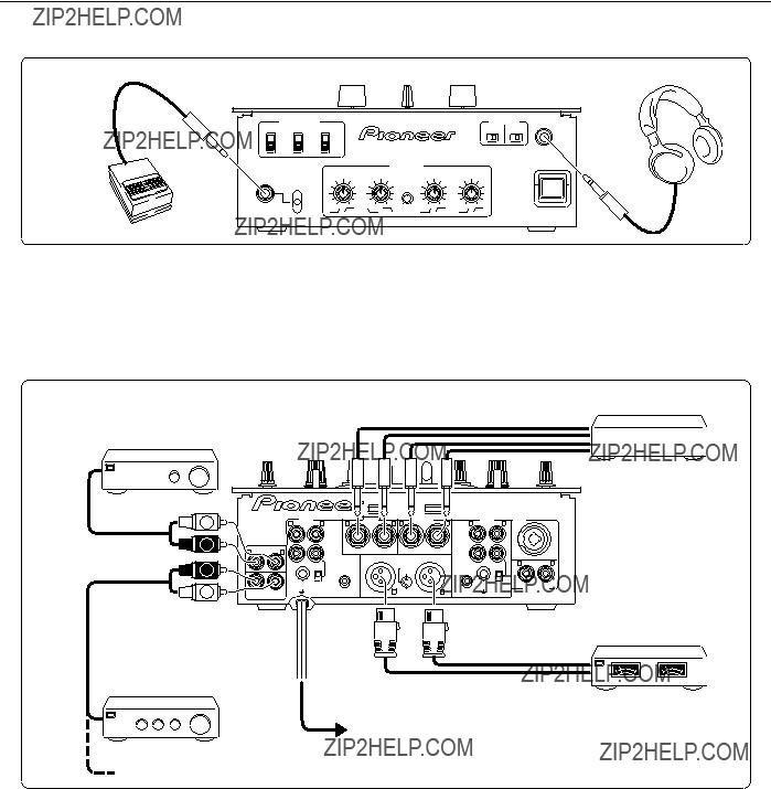
2. Connecting Foot Switch and Headphones (front panel)
Foot switch (pedal switch)
Headphones
Allows the connection of a foot switch with a 6.3 mm monaural plug. The foot switch control effect ON/OFF.
Use to connect headphones with a 6.3 mm diameter stereo plug.
3. Output Connections
Power amplifier
(supporting RCA input)
External effector
7
Power amplifier
(for booth monitor)
CB
8
RL
q
Power cord
Power outlet
Power amplifier
(supporting XLR input)
 To SESSION IN jacks of other mixer
External effector 7
Use a 6.3 mm monaural plug to connect the external effector???s input connectors to the DJ mixer???s SEND jacks. When using an effector with a monaural input, connect it to the L channel output only. The signal actually sent to the effector will represent a mix of L and R signals.
Use a 6.3 mm monaural plug to connect the external effector???s output connectors to the DJ mixer???s RETURN jacks.
When using an effector with monaural output, connect only the L channel input. The signal received from the effector will be input to both L and R channels.
MASTER 2 9
RCA type unbalanced output.
BOOTH/SESSION OUT p
These jacks are provided for booth monitor output.
The sound volume here is controlled by the booth monitor level dial, regardless of the setting of the MASTER LEVEL dial.
When using this unit in tandem with another mixer, connect these jacks to the other mixer???s session input connectors.
6
<DRB1349>

PART NAMES AND FUNCTIONS
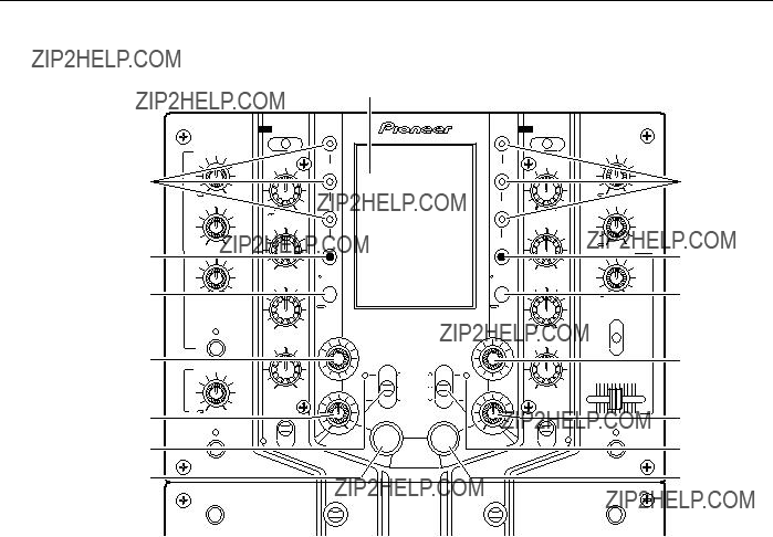
Top Panel (1)
3
4
5
6
7
8
9
20
21
22
23
24
25
26
12
13
14
15
16
17
18
19
30
31
32
33
34
35
36
1
Use to select input signal from MIC jack,
*When [MIC] is selected, the MIC signals are sent directly to the TRIM section without passing through the microphone level and microphone equalizer circuits.
2
Use to adjust the
3 Microphone level dial (MIC LEVEL)
Use to adjust the microphone level (range of adjustment: 0 dB to
4 Microphone equalizer dials (HI/LOW)
HI
Use to adjust microphone treble response (range of adjustment: 10 kHz, ??12 dB).
LOW
Use to adjust microphone bass response (range of adjustment: 100 Hz, ??12 dB).
7
<DRB1349>

PART NAMES AND FUNCTIONS
5
HI
Use to adjust
MID
Use to adjust
LOW
Use to adjust
15 Monitor SELECT switch
MASTER position
selects MASTER output. (This setting allows output regardless of the setting of the MASTER LEVEL dial.)
EFFECT position
Regardless of the [ON/OFF] setting of the EFFECT switch, the output is the signal selected with CUE, with effects added.
CUE position
selects the channel adjusted with the headphone mixing lever (17).
6 MIC SEND button and indicator
When set to On, the indicator lights, and microphone signals are output at the SEND jacks. This function is disabled when the
7 Session input level dial (SESSION IN)
Use to adjust the session input volume (range of adjustment: 0 dB to
8
When set to On, the indicator lights, and
9
When set to [ON], the indicator lights and
When set to [OFF], the indicator goes out and the equalizer circuit is bypassed.
10
Use to select input signal from
*When
11
Use to adjust the
12 MASTER LEVEL dial
User to adjust the master output volume level (range of adjustment: 0 dB to
13 Booth monitor level dial
(BOOTH/SESSION OUT)
Use to adjust the volume level of signals at the BOOTH/ SESSION OUT jacks (range of adjustment: 0 dB to
This level can be set independently of the setting of the MASTER LEVEL dial.
16
HI
Use to adjust
MID
Use to adjust
LOW
Use to adjust
17Headphone mixing lever
This lever does not function when the monitor SELECT switch (15) is set to [MASTER].
When the monitor SELECT switch (15) is set to [EFFECT] or [CUE], moving the lever to the left side produces
18
When set to On, the indicator lights, and
19
When set to [ON], the indicator lights and the
When set to [OFF], the indicator goes out and the equalizer circuit is bypassed.
20
When this button is set to On, fader start and back cue can be performed on the
Whether the operation is initiated by operation of the
*For DJ CD players supporting the fader start/back cue function, see page 5, ???1. Connecting Input Components???.
14 Headphones level dial (PHONES)
Use to adjust the volume level of the headphones output (range of adjustment: 0 dB to
21
Use to set
The lever???s setting angle can be changed in 45?? increments (changing of the angle should be performed by an authorized Pioneer service technician).
8
<DRB1349>

PART NAMES AND FUNCTIONS
22
When lighted, indicates that the front panel???s FADER REVERSE switch has been set so that the
32
When lighted, indicates that the front panel???s FADER REVERSE switch has been set so that the
23
The
When the front panel
*The channel fader curve can be adjusted by means of the front panel FADER CURVE dials.
24
Lights when the
25 C.F.1 FADER START indicator
Lights when
26 Level meters
Displays
27 Cross fader REVERSE indicator
Indicates that the front panel???s FADER REVERSE switch has been set so that the cross fader now operates in reverse (left side is
28 Cross fader lever
When the lever is moved to the left side,
*The cross fader curve can be adjusted individually for
29Operating load adjust screw (FEELING ADJ.)
The hexagonal Allen screw located next to the panel???s slider opening can be rotated with a hexagonal Allen driver to adjust the sliding resistance of the cross fader lever. (See page 17,
???Operating load adjust screw???.)
30
When this button is set to On, fader start and back cue can be performed on the
Whether the operation is initiated by operation of the
*For DJ CD players supporting the fader start/back cue function, see page 5, ???1. Connecting Input Components???.
31
Use to set
This lever???s setting angle can be changed in 45?? increments (changing of the angle should be performed by an authorized Pioneer service technician).
33MASTER LEVEL display button and indicator
When depressed to the On position, the indicator lights and the level meters display the master output (stereo) peak levels. When turned Off, the level meters display the peak levels for
34
The
When the front panel
*The channel fader curve can be adjusted by means of the front panel FADER CURVE dials.
35
Lights when the
36 C.F.2 FADER START indicator
Lights when
9
<DRB1349>
PART NAMES AND FUNCTIONS
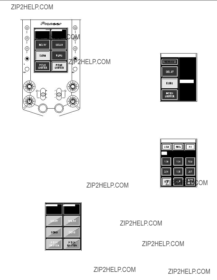
Top Panel (2)
37
38
39
40
41
42
43
44
45
46
47
48
49
50
51
37 Touch Panel
Touch this screen to set effects in accordance with the displayed menus.
*The panel???s screen contrast and backlight luminance can be adjusted (see rear panel items 61 and 63).
40 Fader curve display and
Press to display the fader curve on the touch panel. Holding the button depressed for about one second will cause the touch panel to display the
38
When one of these buttons is pressed, the indicator lights and the corresponding preset effect is enabled. Each BANK button can be recorded with three effects for
39
Press to display the touch panel???s
41
Use to adjust the time parameters of effects applied to
42
Use to adjust the volume (amount) of effects applied to
10
<DRB1349>
PART NAMES AND FUNCTIONS
43
To turn effects [ON], either pull switch forward (switch returns automatically to [OFF] when released) or slide to far side to the [LOCK ON] position. When effects are [ON], the indicator flashes and effects are applied to
49
Use to adjust the volume (amount) of effects applied to
44
Under normal conditions, the automatic BPM counter operates to display the track???s BPM value on the touch panel. Automatic BPM counting may be difficult with some tracks, however. In such cases, or if you wish to deliberately set a different BPM, use the TAP button.
???The BPM value can be changed by rotating the TIME/ SELECT dial while holding the TAP button depressed.
???Tapping the button in time with the beat will cause the function to switch to the manual BPM count mode; the tapped beat will be counted and displayed as the BPM value. Returning to the auto BPM mode is performed from the effect parameter adjust screen (see page 16,
???Automatic Mode BPM Counting???) .
45
When one of these buttons is pressed, the indicator lights and the corresponding preset effect is enabled. Each BANK button can be recorded with three effects for
50
To turn effects [ON], either pull switch forward (switch returns automatically to [OFF] when released) or slide to far side to the [LOCK ON] position. When effects are [ON], the indicator flashes and effects are applied to
51
Under normal conditions, the automatic BPM counter operates to display the track???s BPM value on the touch panel. Automatic BPM counting may be difficult with some tracks, however. In such cases, or if you wish to deliberately set a different BPM, use the TAP button.
???The BPM value can be changed by rotating the TIME/SELECT dial while holding the TAP button depressed.
???Tapping the button in time with the beat will cause the function to switch to the manual BPM count mode; the tapped beat will be counted and displayed as the BPM value. Returning to the auto BPM mode is performed from the effect parameter adjust screen (see page 16,
???Automatic Mode BPM Counting???) .
46
Press to display the touch panel???s
47Fader curve display and
button (FADER CURVE/BANK EDIT)
Press to display the fader curve on the touch panel. Holding the button depressed for about one second will cause the touch panel to display the
48
Use to adjust the time parameters of effects applied to
11
<DRB1349>
PART NAMES AND FUNCTIONS
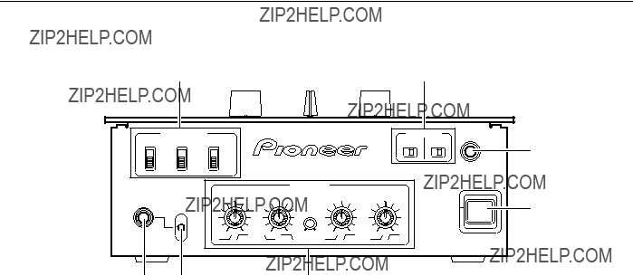
Front Panel
52FADER REVERSE switches
When set to [ON], the top panel???s
When set to [ON], the top panel???s
C.F. ON/OFF
When set to [ON], the top panel???s cross fader REVERSE indicator lights, and the cross fader lever operates in the reverse direction (left side becomes
53FADER START selector switches
C.F.1 /
This switch determines whether the fader start operation for the CD player connected to
When the top panel???s
C.F.2 /
This switch determines whether the fader start operation for the CD player connected to
When the top panel???s
54Headphone output jack (PHONES)
Accepts a 6.3 mm stereo headphones plug.
55POWER switch
56Fader attenuation dials (FADER CURVE)
Use to adjust
Use to adjust
CROSS FADER 1
Use to adjust cross fader???s
CROSS FADER 2
Use to adjust cross fader???s
FADER CUT LAG
Use to adjust mechanical play at both extremes of the cross fader movement (the range in which lever movement produces no effect).
(See page 17, ???Fader attenuation curve adjustment???.)
57 Foot switch channel select switch (FOOT SW
Use to select whether the Effect On/Off foot switch function operates on channel 1
58 Foot switch jack (FOOT SW)
This 6.3 mm RCA jack can be used to connect an On/Off type pedal switch used to turn effects On and Off.
Various types of foot switch are available; some turn On when pressed, some turn Off when pressed, and others have locking mechanisms (alternate On/Off with successive presses). Select the type in accordance with your own preferences.
12
<DRB1349>
PART NAMES AND FUNCTIONS
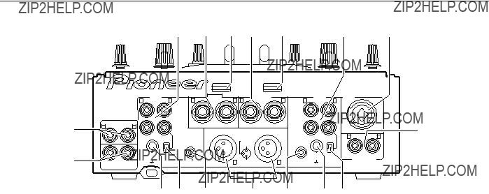
Rear Panel
75
74
73 72 71
59
CD
Connect to audio output from
PHONO / LINE
Connect to audio output from
67
Use to set the input sensitivity at the
*When no analog turntable is used, set this switch to the [LINE] side.
60 External effector output jacks (SEND)
Connect to the input connectors of an external effector. When the top panel switches (MIC SEND,
When using an effector with a monaural input, connect it to the L channel output only. The signal actually sent to the effector will represent a mix of L and R signals.
61Touch panel screen contrast control (CONTRAST)
Use to adjust the top panel???s touch panel contrast.
62External effector return jacks (RETURN)
Connect to the output connectors of the external effector. When using an effector with monaural output, connect only to the L channel input. The signal received from the effector will be input to both L and R channels.
63Touch panel backlight control (BRIGHT)
Use to adjust the top panel???s touch panel backlight luminance.
64
CD
Connect to the audio output of the
PHONO / LINE
Connect to audio output from
65Microphone input jack (MIC)
Connect to a microphone with XLR type or PHONE type plug. When applying effects to the microphone sound, set the top panel???s
66 Session input jacks (SESSION IN)
When using multiple mixers simultaneously, connect the other mixer outputs to these jacks.
68
Connect to the
69
When a Pioneer DJ CD player is connected to the
70 MASTER 1 jacks
XLR type balanced output. Connect to the power amplifier???s balanced input jacks.
71
When a Pioneer DJ CD player is connected to the
72
Use to set the input sensitivity at the
*When no analog turntable is used, set this switch to the [LINE] side.
73
Connect to the
74 BOOTH/SESSION OUT jacks
Connector jacks for booth monitor output. When using this unit in tandem with another mixer, connect these jacks to the other mixer???s session input jacks.
75 MASTER 2 jacks
RCA type unbalanced output. Connect to the power amplifier???s unbalanced input jacks.
13
<DRB1349>
PART NAMES AND FUNCTIONS
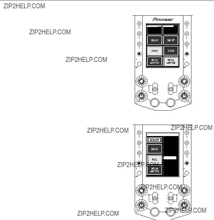
Touch Panel Display Contents
B. Effect select display
Hold the FADER CURVE/BANK EDIT button depressed for about one second to change the screen to the main page effect select menu (settable independently for each channel). Rotate the TIME/SELECT dial to select the effect to be allocated to each button from the list of 50 effects displayed (see page 23, ???Presetting effects???).
(Example):
The button being edited (here, ECHO) = appears highlighted.
Effect list (ECHO)
???
CH 1 BANK EDIT
1 . DE L A Y  2 . ECHO
3 . PAN EC
4 . P I T EC
5 . RV DL Y
6 . DK EC
7 . ROL L
C. Effect parameter adjust display
The touch panel display has four basic patterns
Press the FX ADJ. button to display the effect parameter adjust menu (settable independently for each channel). From this menu, BPM AUTO can be selected. Also, effect selection (cross fader / channel fader) can be selected for fader type.
displays may differ, depending on the kind of settings and status involved.
A. Effect type display (main page)
This display appears when the power is first turned on, or when one of the BANK
The effects for each channel are displayed as buttons, with the currently selected button displayed in reverse illumination (in this manual, indicated as black characters against white background). Other displays show status of foot switch, selected effect parameters, frequency bands subject to effects, TIME display and BPM display.
Select frequency band for effect (HI, MID, =
LOW).
count (BPM AUTO).
D. Fader status display
Press the FADER CURVE/BANK EDIT button to view the fader status in a graphic display. By rotating the front panel FADER CURVE dial, the various attenuation responses can be set in 33 steps, and each step number also displayed. The amount of cross fader lag is also given a numerical display.
??
Cross fader lag data
(FADER CUT LAG)
14
<DRB1349>
PART NAMES AND FUNCTIONS
Touch Panel Display Selection
Changing between the touch panel???s four basic display patterns (A, B, C, D) is performed by pressing the operating buttons at the panel???s sides.
FADER
CURVE
BANK
EDIT
Press FADER CURVE/ BANK EDIT button.
FADER CUT LAG : 1 .0 mm
D Fader status display
15
<DRB1349>
BPM COUNTING
Automatic Mode BPM Counting
This function automatically counts the track???s speed in BPM (Beats Per Minute), displaying the results as a numerical value. The functions does not merely count the bass beat, but uses a computer to calculate the track???s original BPM required by the DJ. The display provides a visual standard in addition to the human ear, thus allowing the DJ to quickly match two tracks possessing differing speeds.
When auto mode is used to count BPM, the calculated BPM value is displayed on the LCD panel, allowing quick matching of tracks with differing speeds. (Counting range: 70.0 to 180.0 BPM)
The display flashes during BPM counting.
*Some tracks may not be counted properly, in which case manual count should be used.
(See page 11, top panel items 44, 51)
Touch panel (main page)
7 Selecting Auto Mode
1.Press the FX ADJ. button to cause the touch panel screen to display the effect parameter
adjust menu.
If the
AUTO lights in auto mode.
BPM value display
BPM value display
TAP lights during manual count mode (TAP button input)
2.Press the BPM TAP button (displayed in manual mode), to display the BPM AUTO button.
??The BPM value can be input directly by rotating the TIME/SELECT dial while holding the TAP button depressed.
16
<DRB1349>
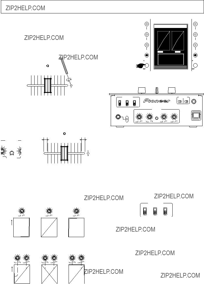
FADER OPERATIONS
Adjusting Fader Lever Operating Sensation
Operating load adjust screw (FEELING ADJ.)
The supplied hexagonal Allen driver can be used to adjust the hexagonal Allen screw located next to the top panel???s cross fader slider opening, thus modifying the sliding resistance of the lever. Rotate the screw clockwise to increase sliding resistance and counterclockwise to reduce resistance.
REVERSE
FEELING
ADJ.
Cross fader lag adjustment
The mechanical play (the lag or range of movement in which no functional effect takes place) at the two extreme ends of the top panel cross fader lever movement can be adjusted by using the front panel???s FADER CUT LAG dial, within a range of
Fader attenuation curve adjustment
The front panel???s FADER CURVE dials can be used to adjust the attenuation curve response of the cross fader and channel fader. The cross fader can be adjusted independently for
7 Channel fader curve adjustment
LEVEL
Channel fader lever positions
7 Cross fader curve adjustment (CROSS FADER 1, 2)
LEVEL
Cross fader lever positions
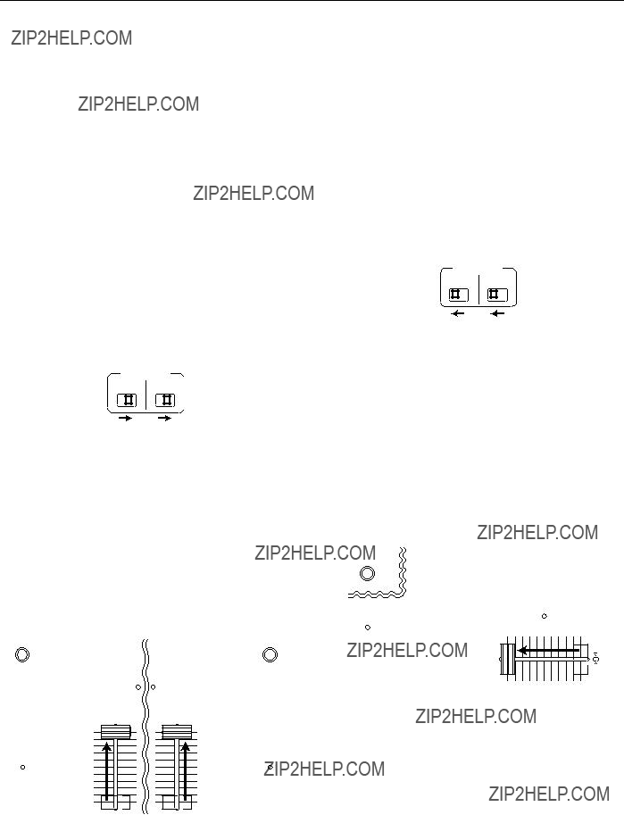
Fader reverse function
The operating directions of the
When the
When the C.F. FADER REVERSE switch is set to [ON], the top panel???s cross fader REVERSE indicator lights, and the lever operating direction is reversed (left side becomes
Fader Start Function
When the
17
<DRB1349>
FADER OPERATIONS
Cross fader start play and back cue play
When the
When the cross fader lever reaches the left
*Back cue is performed even if the input selector switch is not set to CD.
Start playback with channel fader
1To control a connected CD player, set the front panel FADER START selector switch for the corresponding channel to its
When using the
FADER START
C.F. 1
??If the cue point has already been set, there is no need to set the CD player again for standby at the cue point.
??After playback has once begun, moving the channel fader lever back to the ???0??? scale mark will cause the CD player to return to its cue point and enter the standby mode again (back cue).
Start playback with cross fader
1To control a connected CD player, set the front panel FADER START selector switch for the corresponding channel to its [C.F.1] or [C.F.2] position.
When using cross fader lever to start the
FADER START
C.F. 1
2Press the top panel FADER START button so that the indicator lights.
When the
When the
2Press the top panel FADER START button so that the indicator lights.
When the
When the
3 Set the channel fader lever to the [0] scale mark.
4Adjust the CD player to its cue point and set for cue point standby.
5Begin moving the channel fader lever with the timing you wish, thereby beginning playback on the CD player.
3Move the cross fader lever to the side opposite from the channel you wish to start.
4 Adjust the CD player to its cue point and set for cue point standby.
5Begin moving the cross fader lever with the timing you wish, thereby beginning playback on the CD player.
FADER START
REVERSE
C.F.1 FADER START
FEELING
ADJ.
??If the cue point has already been set, there is no need to set the CD player again for standby at the cue point.
??If the cross fader lever is moved fully after the beginning of playback, the opposite channel???s CD player will return to its cue point and enter standby there (back cue).
18
<DRB1349>

EFFECT FUNCTIONS
Types of Effects
This unit is equipped with a beat effector linked to the BPM, and fader effector linked to the channel or cross fader, producing a total of 50 basic effects, but an even wider variety of effects can be produced by varying the parameters of each effect.
Beat Effector (effects linked to BPM)
(*1) When the channel fader or cross fader is used to lowering sound volume, no effect sounds will be heard, even if monitor SELECT switch is set to the [EFFECT] position.
(*2) When EFFECT switch is turned OFF, no effect sounds will be heard even if the monitor SELECT switch is set to the [EFFECT] position.
19
<DRB1349>

EFFECT FUNCTIONS
20
<DRB1349>
(*1) When the channel fader or cross fader is used to lowering sound volume, no effect sounds will be heard, even if monitor SELECT switch is set to the [EFFECT] position.
(*2) When EFFECT switch is turned OFF, no effect sounds will be heard even if the monitor SELECT switch is set to the [EFFECT] position.
21
<DRB1349>

EFFECT FUNCTIONS
Using the Effect Functions
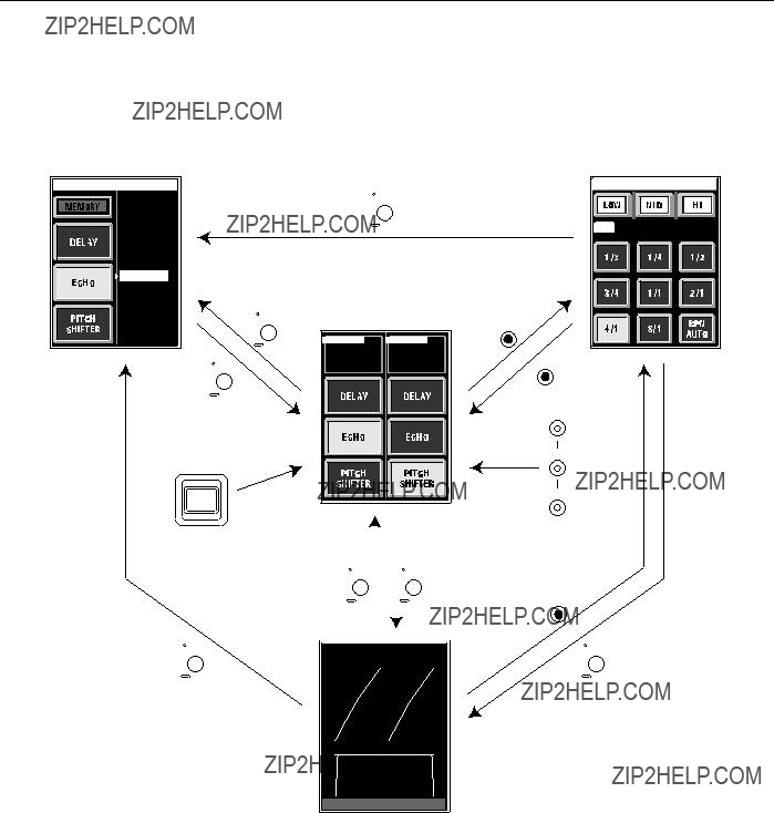
The basic procedures is as follows: [Select effect type] = [Set parameters (while monitoring through headphones] =[Set EFFECT switch to ON].
Below are examples of this basic operation procedure; other effects are produced in much the same way:
[Example 1] Apply delay to
1.Touch the touch panel???s
??? If the DELAY button is not displayed, select and display
the button as follows:
1Hold the
2Of the touch panel???s three buttons, select (touch) the one in which you wish to record the DELAY.
3Rotate the TIME/SELECT dial to select DELAY.
4Press (touch) the MEMORY button.
5Press the FADER CURVE/BANK EDIT button to leave the effect select menu.
???If DELAY is preset in the BANK 1, 2, or 3 buttons, DELAY can be selected by pressing the corresponding button (see page 23 ???Presetting Effects.???)
2.Press the
3.Use the touch panel???s LOW, MID, and HI buttons to select the frequency ranges for the effect.
???The selected range button will appear highlighted.
*It may not be possible to select the frequency range, depending on the type of effect.
4.Press the touch panel???s 1/8 to 8/1 buttons as desired to select the delay time (parameter value setting).
??? Set delay time of 1/8 to 8/1 for each beat of BPM.
??? Set monitor SELECT switch to [EFFECT] to confirm the effect sound through the headphones (effects marked with the note *1 on the effects chart cannot be heard unless the EFFECT switch is set to [ON]).
??? The TIME/SELECT dial can be rotated to produce even finer delay time settings. Setting delay time of 1/2 per beat of tempo (BPM) will cause the touch panel???s 1/2 button to be highlighted, and this can be used as a general reference when adjusting the parameter.
5.Use the MIX/DEPTH dial to set the level balance between sound source and delay sound.
??? Rotate to left to reduce, and rotate to right to increase the delay sound.
6.Set EFFECT switch to [ON] or [LOCK ON].
??? The EFFECT indicator will begin flashing red, and the effect (delay) will be applied to the master output.
??? When the EFFECT switch is set to [ON] by pulling the switch forward, the switch will automatically return to [OFF] when released.
Note:
???Select effects only when the EFFECT switch is in the [OFF] position. If effects are selected when the EFFECT switch is in the [LOCK ON] position, noise may be produced.
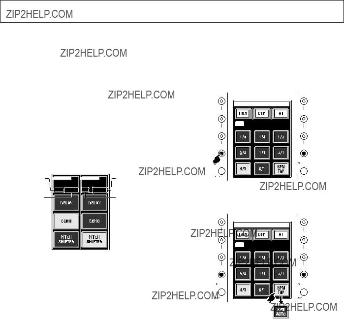
[Example 2] Apply fader roll to
1.Touch the touch panel???s
???If the FADER ROLL button is not displayed, select and display the button as follows:
1Hold the
2Of the touch panel???s three buttons, select (touch) the one in which you wish to record the FADER ROLL.
3Rotate the TIME/SELECT dial to select FADER ROLL.
4Press (touch) the MEMORY button.
5Press the FADER CURVE/BANK EDIT button to leave the effect select menu.
???If FADER ROLL is preset in the BANK 1, 2, or 3 buttons, FADER ROLL can be selected by pressing the corresponding button (see page 23 ???Presetting Effects.???)
2.Press the
3.Use the touch panel???s LOW, MID, and HI buttons to select the frequency ranges for the effect.
???The selected range button will appear highlighted.
*It may not be possible to select the frequency range, depending on the type of effect.
4.Press the touch panel???s 1/2, 1/1, and 2/1 buttons as desired to select the roll time (parameter value setting).
??? Standard roll times can be set as 1/2, 1/1, or 2/1.
??? Set monitor SELECT switch to [EFFECT] to confirm the effect sound through the headphones (effects marked with the note *1 on the effects chart cannot be heard unless the EFFECT switch is set to [ON]).
??? The TIME/SELECT dial can be rotated to produce even finer roll time settings. Setting roll time to 1/1 per beat of tempo (BPM) will cause the touch panel???s 1/1 button to be highlighted, and this can be used as a general reference when adjusting the parameter.
5.Use the MIX/DEPTH dial to set the roll sound level.
??? Rotate to left to reduce, and rotate to right to increase the roll sound.
6.Use touch panel???s CROSS FADER button to select fader.
??? The fader used for fader effects can be set to either channel fader or cross fader.
7.Set EFFECT switch to [ON] or [LOCK ON].
??? The EFFECT indicator will begin flashing red, and the effect will be applied to the master output.
??? When the EFFECT switch is set to [ON] by pulling the switch forward, the switch will automatically return to [OFF] when released.
Note:
???Make selection of effects and type of fader (channel or cross) only when the EFFECT switch is in the [OFF] position. If effects are selected when the EFFECT switch is in the [LOCK ON] position, noise may be produced.
22
<DRB1349>
EFFECT FUNCTIONS
Presetting Effects
Of the effects displayed on the touch panel???s main page (effect type menu), three types can be set for each channel
1.Select the channel
???Press and hold depressed for about one second the FADER CURVE/BANK EDIT button corresponding to the channel
2.Change the effect
1Press the BANK button (1/2/3) whose setting you wish to change.
2Of the three touch panel buttons, press (touch) the one in which you wish to record a new effect.
3Rotate the TIME/SELECT dial to select effect. 4Press (touch) the touch panel???s MEMORY button.
If a different BANK button is pressed or EFFECT switch operated without first pressing the MEMORY button, no effect will be recorded.
???Up to three effects can be recorded in a single BANK button. Repeat steps
3.Leave the effect selection (BANK EDIT) menu
???Press the FADER CURVE/BANK EDIT button to leave the effect selection menu.
BANK 1  BANK 1
23
<DRB1349>

EFFECT FUNCTIONS
Effect Parameters
The 50
7 Beat effects
24
<DRB1349>
(*1) When the channel fader or cross fader is used to lowering sound volume, no effect sounds will be heard, even if monitor SELECT switch is set to the [EFFECT] position.
(*2) When EFFECT switch is turned OFF, no effect sounds will be heard even if the monitor SELECT switch is set to the [EFFECT] position.
7 Fader effects
25
<DRB1349>

EFFECT FUNCTIONS
(*1) When the channel fader or cross fader is used to lowering sound volume, no effect sounds will be heard, even if monitor SELECT switch is set to the [EFFECT] position.
(*2) When EFFECT switch is turned OFF, no effect sounds will be heard even if the monitor SELECT switch is set to the [EFFECT] position.
BLOCK DIAGRAM
MIC
PHONO /LINE
CD
PHONO /LINE
CD
FOOT SW 


SEND
FOOT SW
EFFECTOR
OFF
26
<DRB1349>

TROUBLESHOOTING
Incorrect operations are often mistaken for trouble and malfunctions. If you think there is something wrong with this component, check the points below. Sometimes the trouble may originate from another component. Thus, also check the other electrical appliances also in use.
If the trouble cannot be rectified even after checking the following items, contact your dealer or nearest PIONEER service center.
Static electricity or other external interference may cause the unit to malfunction. To restore normal operation, turn the power off and then on again.
27
<DRB1349>

SPECIFICATIONS
Audio Section
Input terminal (input level/impedance)
Microphone equalizer (MIC)
For improvement purposes, specifications and design may be subject to modification without notice.
PIONEER CORPORATION
PIONEER ELECTRONICS (USA) INC.
Multimedia and Mass Storage Division: 2265 East 220th Street, Long Beach, CA 90810, U.S.A. TEL:
PIONEER ELECTRONICS OF CANADA, INC.
Industrial Products Department: 300 Allstate Parkway, Markham, Ontario L3R OP2, Canada TEL: