Should this product require service in the U.S.A. and you wish to locate the nearest Pioneer Authorized Independent Service Company, or if you wish to purchase replacement parts, operating instructions, service manuals, or accessories, please call the number shown below.
8 0 0 ??? 4 2 1 ??? 1 4 0 4
Please do not ship your product to Pioneer without first calling the Customer Support
Division at the above listed number for assistance.
Pioneer Electronics (USA) Inc.
Customer Support Division
P.O. BOX 1760, Long Beach,
CA 90801-1760, U.S.A.
For warranty information please see the Limited Warranty sheet included with your product.
Should this product require service in Canada, please contact a Pioneer Canadian
Authorized Dealer to locate the nearest Pioneer Authorized Service Company in Canada.
Alternatively, please contact the Customer Satisfaction Department at the following address:
Pioneer Electronics of Canada, Inc.
Customer Satisfaction Department
300 Allstate Parkway, Markham, Ontario L3R OP2 1(877)283-5901
For warranty information please see the Limited Warranty sheet included with your product.
Si ce produit doit ??tre r??par?? au Canada, veuillez vous adresser ?? un distributeur autoris?? Pioneer du Canada pour obtenir le nom du Centre de Service Autoris?? Pioneer le plus pr??s de chez-vous. Vous pouvez aussi contacter le Service ?? la client??le de Pioneer:
Pioneer ??lectroniques du Canada, Inc. Service ?? la client??le
300, Allstate Parkway, Markham, Ontario L3R OP2 1(877)283-5901
Pour obtenir des renseignements sur la garantie, veuillez vous reporter au feuillet sur la garantie restreinte qui accompagne le produit.
S018_A_EF
Published by Pioneer Corporation.
Copyright ?? 2004 Pioneer Corporation.
All rights reserved.
PIONEER CORPORATION
4-1, Meguro 1-Chome, Meguro-ku, Tokyo 153-8654, Japan
PIONEER ELECTRONICS (USA) INC.
P.O. BOX 1540, Long Beach, California 90810-1540, U.S.A. TEL: (800) 421-1404
PIONEER ELECTRONICS OF CANADA, INC.
300 Allstate Parkway, Markham, Ontario L3R OP2, Canada TEL: 1-877-283-5901
PIONEER EUROPE NV
Haven 1087, Keetberglaan 1, B-9120 Melsele, Belgium TEL: 03/570.05.11
PIONEER ELECTRONICS ASIACENTRE PTE. LTD.
253 Alexandra Road, #04-01, Singapore 159936 TEL: 65-6472-7555
PIONEER ELECTRONICS AUSTRALIA PTY. LTD.
178-184 Boundary Road, Braeside, Victoria 3195, Australia, TEL: (03) 9586-6300

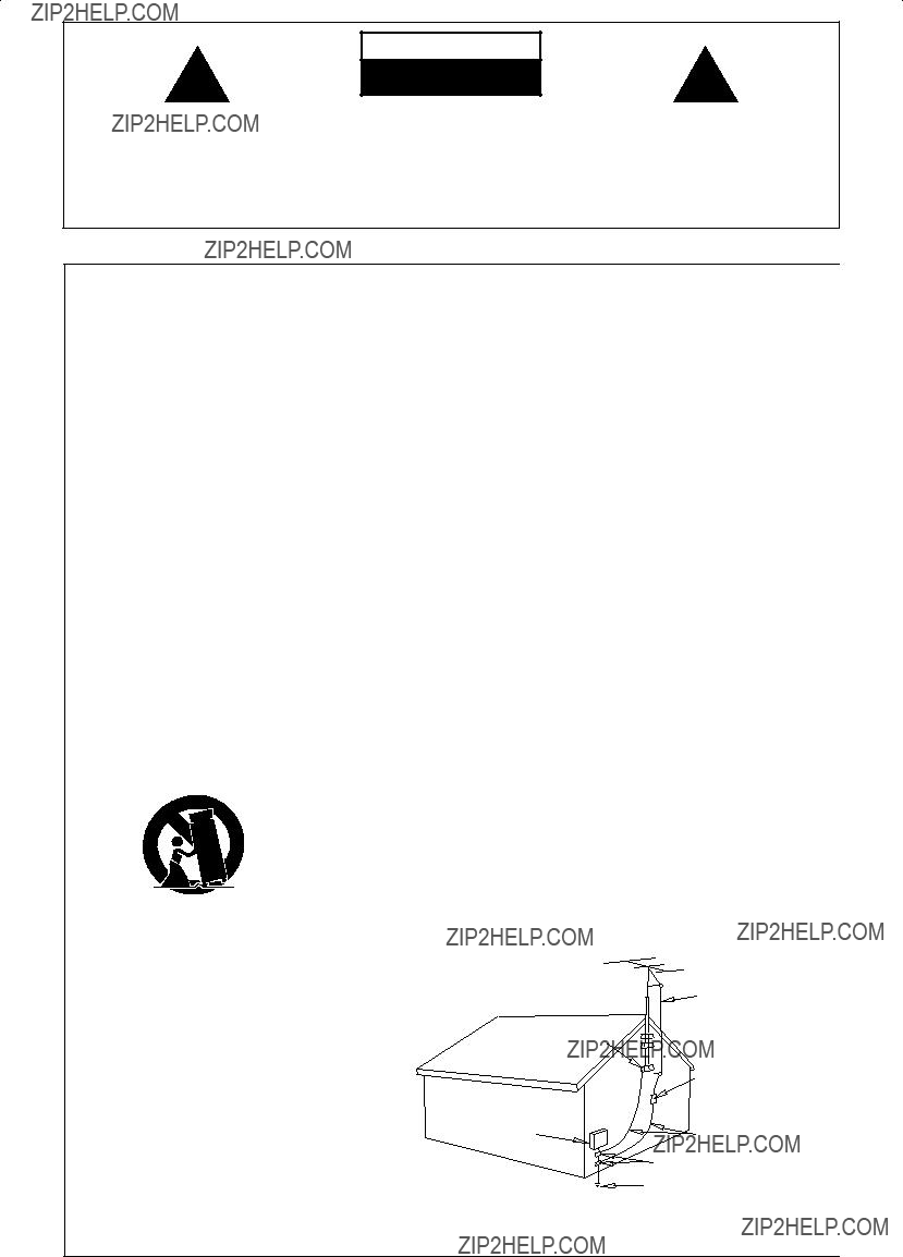


 Caution
 Optical cable
 Video cord
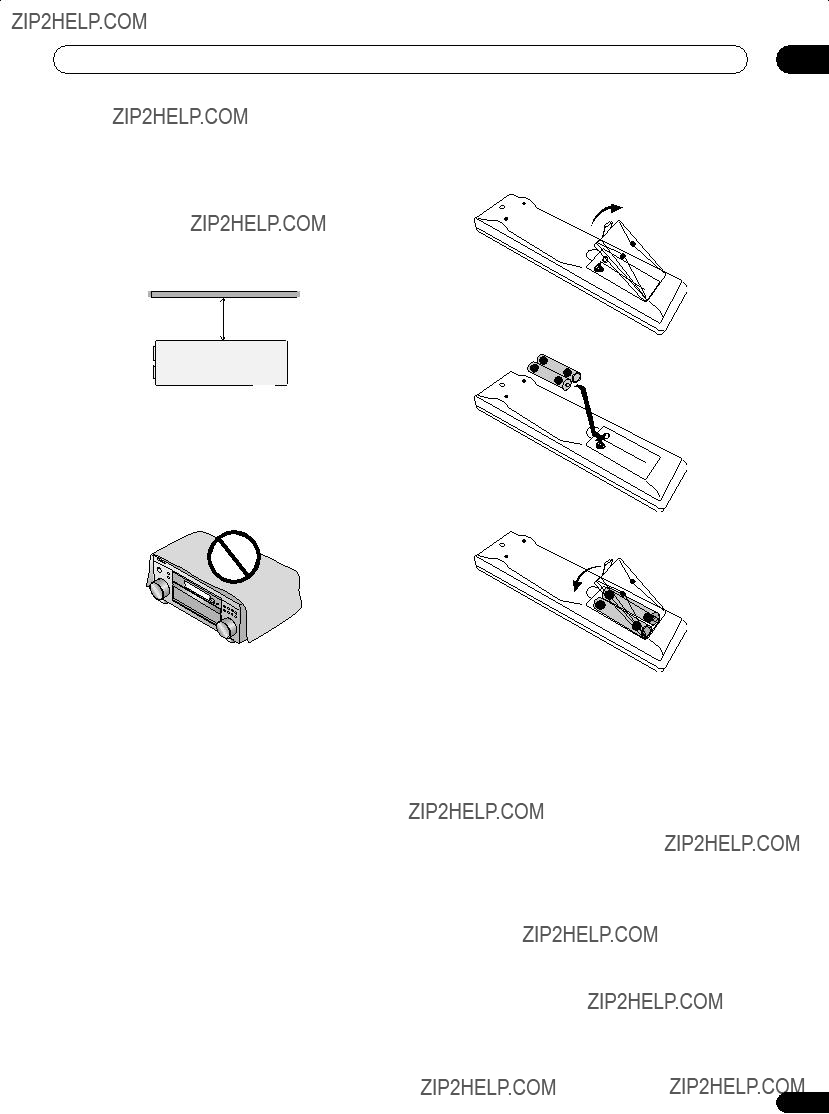
 Caution
 Note
Note Important
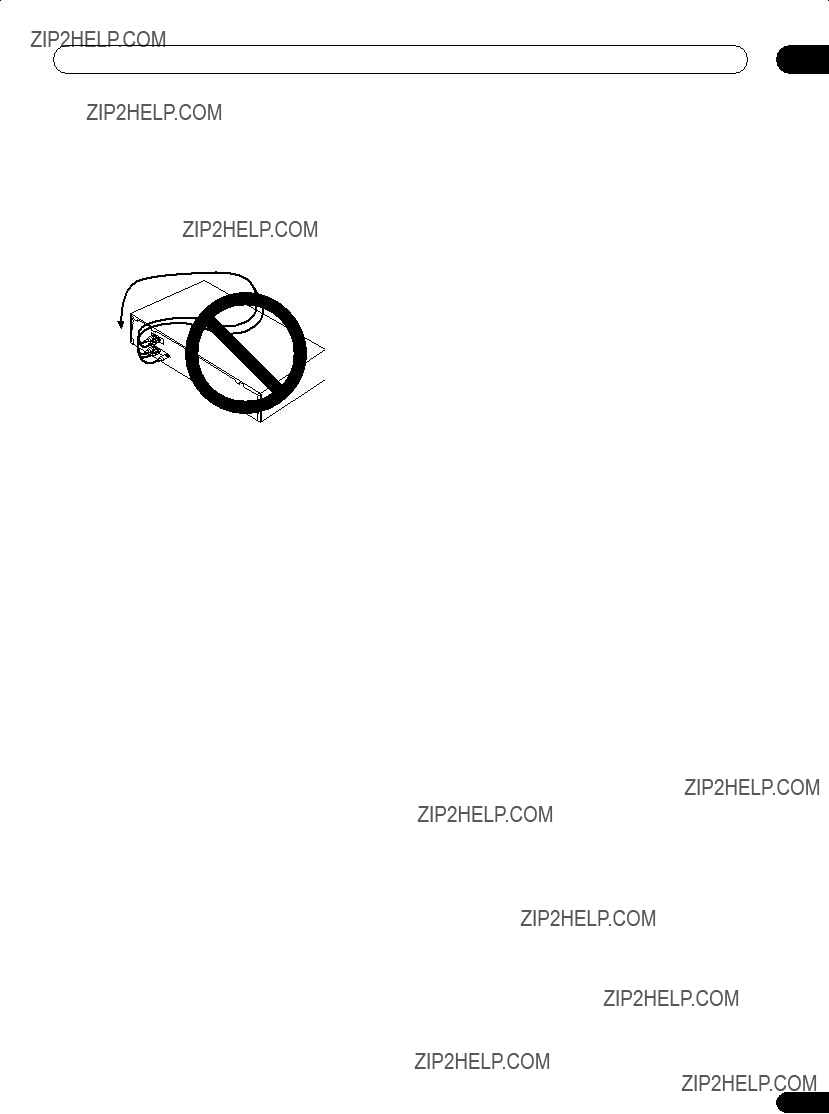
 Caution

 Note
Note Note
Note Note
Note
 Important

 Note
Note
 REC PLAY
 Tip
Tip


 Note
Note Caution
 Note
Note Caution
 Caution
 Note
Note Note
Note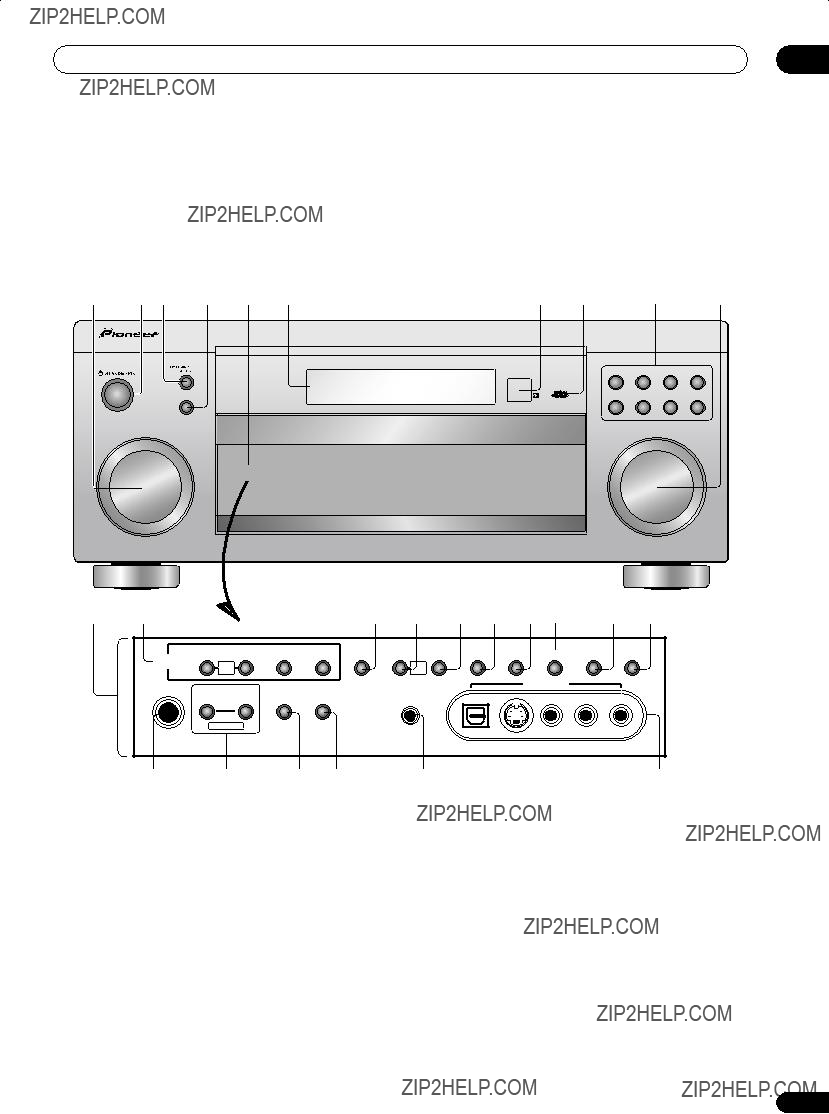


 Tip
Tip Note
Note Note
Note Note
Note Note
Note
 Tip
Tip Note
Note Note
Note
 Note
Note Note
Note
 Note
Note
 Note
Note
 Note
Note Note
Note Note
Note
 Note
Note

 Important
 [
[ 


 Caution
 Note
Note
 Note
Note [
[ 
 Note
Note
 Note
Note
 Tip
Tip Note
Note
 Note
Note
 Note
Note Note
Note
 Note
Note


 Caution
 Note
Note
 Caution
 Caution
 Important
 Note
Note
 Note
Note Note
Note
 [
[ 


 Note
Note Tip
Tip
 [
[ 


 dB Output (Level/Impedance)
 Note
Note dB
dB dB
dB
