OTHER ASPECTS
Most electronic ballasts are suitable for use in emergency lighting installations. Distinction must, however, be made between centralised and decentralised emergency lighting. Provided the correct voltages are applied, electronic ballasts can be used in centralised installations. When talking about a decentralised emergency lighting set-up, many different configurations are possible. In general the emergency converter must have a four-pole switch-over relay to ensure that the wiring between the HF ballast and the lamp is completely shut off when the emergency lighting is in operation. Interference from the emergency converter to the HF ballast is then out of the question. Some emergency lighting installations equipped with a three-pole switch-over relay can also be used in combination with HF electronic ballasts, but this has to be checked and warranted by the emergency lighting supplier and installer.
Fluorescent lamps can be dimmed with dimmable HF electronic ballasts, such as the Philips HF-REGULATOR types.
Philips HF-REGULATOR ballasts can be controlled by a 1-10 V DC input from various types of regulating systems.
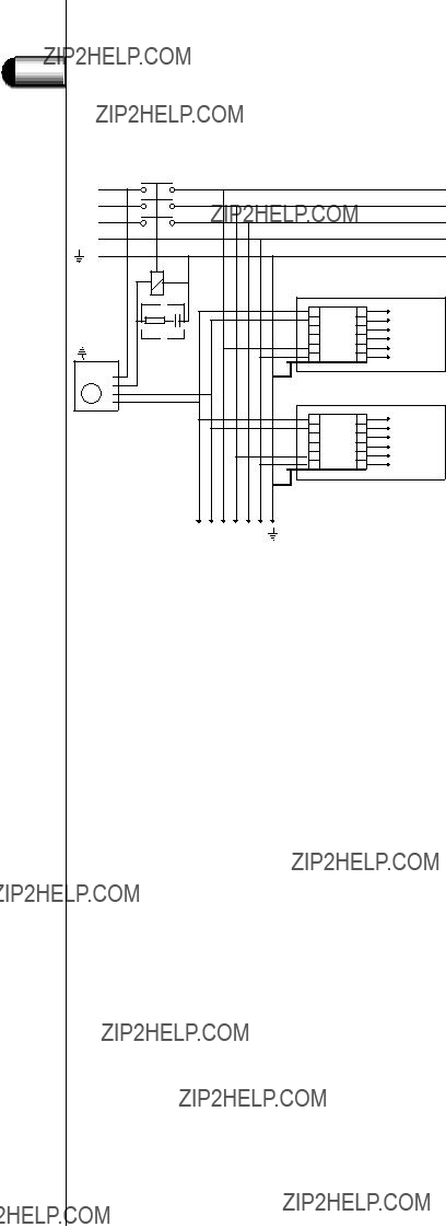
In Fig. 15, an example is shown of an electronic potentiometer (LPS 100) regulating the dimming level via the +/- DC input on the HF-REGULATOR ballast.
It can be seen that a total number of up to 100 HF-R ballasts powered by different phases can be controlled (see Fig. 16). The control wiring must be dealt with like 230 V wiring.
For more information on the installation of different control systems, contact your local sales agent.
27
 5
5