User
Manual


 x
x
User
Manual
x

?? 2004 GE Security
All Rights Reserved.
Any GE Security software supplied with GE Security products is proprietary and furnished under license and can be used or copied only in accordance with the terms of such license.
This document contains proprietary information that is protected by copyright. No part of this document may be reproduced or transmitted in any form or by any means without the prior written permission of
GE Security.
The information contained in this document is subject to change without notice. GE Security in keeping pace with technological advances, is a company of product innovation. Therefore, it is difficult to ensure that all information provided is entirely accurate and
consequence, directly or indirectly, of the use or application of any of the contents of this document.
For the latest product specifications, visit GE Security online at www.
For technical support before and after installation, call
Technical support is available 24 hours a day, 7 days a week.
Web:

Table of Contents

1 Philips ProBridge
1.1 Philips ProBridge Description
The Kalatel
Kalatel Components:
(1)
???(1)
???(2) P/N
???(1) P/N
???(1) P/N
(1) P/N
???(1) P/N
Philips Components:
???(1) Philips Data Converter Unit (LTC 8780).
???(1) Philips AutoDome.
1.2 Compatibility
The
Compatible units include the Kalatel DVMRe digital video units and various Kalatel Multiplexer models (Simplex, Triplex, Matrix). Please check the specifications of the particular Kalatel product for
1.3 Installation Environment
Power: Ensure that the installation site???s AC power is stable and within the rated voltage of the external power supply. If the site???s AC power is likely to have spikes or dips, use power line conditioning or an Uninterruptible Power Supply.

Temperature: Observe the unit???s ambient temperature specifications when choosing a location for the unit. Extremes of heat or cold beyond the specified operating temperature limits may cause the unit to fail. Do not install this unit on top of other hot equipment.
Moisture: Do not expose the unit to rain or moisture. Moisture can damage internal components. Do not install this unit near sources of water.
RS485 Limitations: Total length of the
1.4 Power
The ProBridge is furnished with a power supply (110 or 240 VAC). Do not use any other power supply with this product. The manufacturer accepts no responsibility for damage caused by the use of any other power supply.
Make sure installation is complete and all connections are made before applying power to the unit.
Power Supply Input
Voltage: 120 Volt AC
Tolerance: ??10%
Frequency: 60 Hz
Power Supply Output
Voltage: 12 Volt DC
Current: 110mA
Power: 1.3 Watts
Connector: 2.1mm female barrel. Center Positive
Power Supply Input
Voltage: 220 Volt AC
Tolerance: ??10%
Frequency: 50 Hz
Power Supply Output
Voltage: 12 Volt DC
Current: 110mA
Power: 1.3 Watts
Connector: 2.1mm female barrel. Center Positive

1.5 Installation Steps Summary
Carefully and completely read the manuals for each piece of equipment before attempting to install and connect this equipment.
Before you start connecting other optional accessory equipment to your system, make sure that all, power, video, VCR, and monitor connections are completed, and everything is working correctly.
Wire the telemetry equipment according to that unit???s installation instruction. Use the internal diagnostic testing capabilities of the telemetry receiver to verify that the power and connections to the lens and motors are correct, and function properly.
Using the Diagram on the following page, connect the equipment in the following order:
1.Connect the
2.Connect the
3.Supply power to the Kalatel unit first and the
4.Using the provided cable, connect from the ProBridge RCVR/DRVR port to the Philips Data Converter Unit (LTC 8780). See the Philips Data Converter Unit???s (LTC 8780) installation manual for information on connecting the LTC 8780 to the AutoDome.
5.Set the ID addresses for the Philips Dome according to the table later in this manual.
6.Via a networked connected PC with WaveReader software, connect to the DVMRe unit and confirm proper control and operation of the PTZ unit.
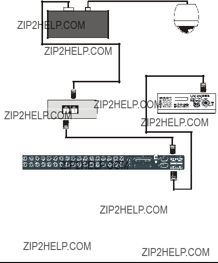
1.6 Connection Diagrams
This drawing depicts one Philips AutoDome connected via an RS485/422 network to a Kalatel DVMReTriplex unit, that provides remote PTZ control over Ethernet via WaveReader software, and a
Philips AutoDome

2 Cable Specifications
ProBridge to Kalatel Unit Cable
Part Number :
Communication Type:
Connector Type: RJ45 ,RJ45
Cable Required: 5 Foot RJ45 to RJ45 Triplex RS485 Cable (Supplied). Connects ProBridge to Triplex and
ProBridge to Philips Data Converter Unit
Part Number :
Communication Type: RS232
Connector Type:
Cable Required: 6 Foot

3 Troubleshooting
If you are unable to verify control of the PTZ camera, please do the following:
1.Check that each device is properly powered.
2.Check that all cables and cable connections are correct.
3.Verify that the Dome addresses and Unit ID are correct.
4.If the interface still does not work correctly contact Technical Support.
4 Unit Settings
4.1 Configuring ProBridge Jumpers
The unit ships from the factory with the correct settings for most applications and should not require the installer to open the unit and change the jumper settings. However, for trouble shooting purposes we have included the default jumper settings.
Opening The ProBridge
Place the ProBridge unit face down. Using a small Phillips screwdriver, carefully remove the screws located near each corner of the unit. Once the screws have been removed, lift the cover to detach.
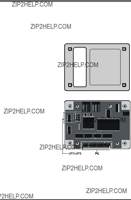
Identifying The Jumpers
With the cover removed, orient the unit as shown here. There are two sets of configurable jumpers. One set, located on the left side of the board, controls how the unit communicates (JP2, JP3, JP4 and JP5). The other set, located at the bottom of the board (P6, twelve pin header) determines specific configuration elements for equipment interfacing.
ProBridge Circuit Board
Default Jumper Settings
The default jumper settings are listed below:

5 Specifications

6 Appendix
6.1
The Philips ProBridge
Each camera input, whether a fixed camera or a Pan/Tilt/Zoom (P/T/Z) unit, is connected to a Kalatel unit input. The Kalatel unit has an
The
The
Most units have looping
#24 AWG, twisted pair with shield
Less than 25 ohms per 100 foot, nominal.
6.2 Philip AutoDome Addressing
The Philips AutoDome can be addressed from 1 to 9998. The
Camera Mapping

Philips AutoDome Addresses are calculated as follows:
Philips AutoDome Address = Camera Address + 32 X (Network Address ??? 1)
Philips Data Converter Unit Switch Setting
Set the switches on the LTC8780 as follows:
S101: Switches 1, 3, and 4 set to OFF. Switch 2 set to ON.
S102: Switches 1
See Philips LTC8780 manual for details.
6.3 Using Kalatel Keypads
Keyboards
In some specific cases keyboards may be used in conjunction with the


 ALT
ALT
 9 25
9 25 
 10 26
10 26 
 11 27
11 27 
 12 28
12 28
 13 29
13 29 
 14 30
14 30 
 15 31
15 31 
 16 32
16 32 
#
Preset Key
Keyboard Layout
6.4 AUX Operations
The remote keyboard has 8 AUX function keys that can be assigned to do some Philips AutoDome features as follows:
6.5 Preset Operations
The Philips AutoDome can store up to 99 preset operations

Preset Setup for
To set a new Preset position:
1.Move the camera to the desired position by using the joystick or arrow keys.
2.Press Preset key twice. The LCD will display: ???Set Preshot Number???? Select camera key number 1 to 16 (17 to 32 with Shift key turned on) to set the preset number from 1 to 32.
3.Verify by calling up that preset number: Move to another position then press Preset key once. The Keyboard LCD will display: ???Go to Preshot Number???? Select the preset number to go to that preset position.
To clear an existing Preset position:
1.Press the Preset key twice. The Keyboard LCD will display: ???Set Preshot Number???? Select the camera key to the desired preset number. The Dome will go to that existed Preset position and clear this preset.
2.Move the Dome to the new position by using the joystick or arrow keys.
3.Repeat step 1: Press Preset key twice. The KB3 LCD will
display: ???Set Preshot Number???? Select the camera key to the preset number. Now, the new preset position is stored.
4.Verify by calling up that preset number: Move to another position then press Preset key once. The KB3 LCD will display: ???Go to Preshot Number???? Select the preset number to go to that preset position.
Preset Setup WaveReader
To set a new Preset position:
1.Navigate the camera to the desired location, select the desired preset from the drop down list box, then click Set.
2.To send the camera to the desired preset, select the preset from the drop down list box, then click Go To.

7 Warranty Information
7.1 Factory Service
If the unit requires factory service, contact the dealer who supplied the unit to you for the correct procedures on returning the unit to the factory or the nearest factory service center.
If the dealer is not available, contact the manufacturer of the unit as detailed below and request a Return Material Authorization number (RMA). The unit???s serial number must be provided before an RMA number can be issued. Units returned to the factory for service must have freight and insurance prepaid, and must show the RMA number clearly on all shipping documents. The failure symptoms must be clearly described by the operator and enclosed with the unit together with a copy of the original supplier???s invoice. Failure to comply with these instructions will delay service of the unit, and may result in the unit not being accepted by the Repair Center.
7.2 Factory Address
GE Security
Attention: Repair Center
3050 Red Hill Ave.
Costa Mesa, CA 92626
United States of America
Telephone:
In Oregon:
Fax:
For warranty information, see the following page.
7.3 Warranty
GE Security warrants all of its equipment for three years from the date of purchase. This warranty covers any defects in materials and workmanship. Equipment failures that are due to improper installation, modification, abuse, or acts of nature will not be covered by this warranty. The repair department will evaluate all equipment returned for repair to determine warranty coverage. The Tech Support Manager will resolve any questions that may arise during evaluation to make a final determination.
The warranty specifically covers any defects in material and workmanship and does not cover equipment that has been abused, damaged, or modified.
For all warranty repairs, GE Security will cover all costs, including parts, labor, and shipping. Repaired equipment will be returned via the same method of shipment in which it was received. If a customer requests a faster return shipment, the difference will be charged.
For all

Note: Customers requesting an estimate prior to repair will be notified by phone. If they cannot be reached, they will be notified by fax. If we are unable to reach the contact person for repair authorization after one phone attempt and two fax attempts, the equipment will be returned without being repaired. We will hold equipment no longer than two weeks.
Advance Replacement Policy
When an advance replacement is required, we will send the customer replacement equipment from our stock and receive the returned product in exchange. The received equipment will be evaluated and the repair department will determine whether it is a warranty replacement. If it is
???Fewer than 45 days from purchase, GE Security will replace the product with new equipment.
???From 45 days to 1 year from purchase, GE Security will replace the product with refurbished equipment.
???From 1 year to 3 years from purchase, the product must be sent in for repair. Advance replacements will be sent for a fee of $100.
If you have questions about this policy, please contact GE Security???s RMA Department at