Flow Meter Installation and
Operation Guide
For software version CF 4.7 and higher
1500 North Belcher Road ??? Clearwater, FL 33765 ??? Tel (727)
Flow Meter Installation and
Operation Guide
For software version CF 4.7 and higher
1500 North Belcher Road ??? Clearwater, FL 33765 ??? Tel (727)
SAFETY INFORMATION
This meter was calibrated at the factory before shipment. To ensure correct use of the meter, please read this manual thoroughly.
Regarding This Manual:
???This manual should be passed on to the end user.
???Before use, read this manual thoroughly to comprehend its contents.
???The contents of this manual may be changed without prior notice.
???All rights reserved. No part of this manual may be reproduced in any form without ONICON???s written permission.
???ONICON makes no warranty of any kind with regard to this material, including, but not limited to, implied warranties of merchantability and suitability for a particular purpose.
???All reasonable effort has been made to ensure the accuracy of the contents of this manual. However, if any errors are found, please inform ONICON.
???ONICON assumes no responsibilities for this product except as stated in the warranty.
???If the customer or any third party is harmed by the use of this product, ONICON assumes no responsibility for any such harm owing to any defects in the product which were not predictable, or for any indirect damages.
Safety Precautions:
The following general safety precautions must be observed during all phases of installation, operation, service, and repair of this product. Failure to comply with these precautions or with specific WARNINGS given elsewhere in this manual violates safety standards of design, manufacture, and intended use of the product. ONICON Incorporated assumes no liability for the customer???s failure to comply with these requirements. If this product is used in a manner not specified in this manual, the protection provided by this product may be impaired.
The following symbols are used in this manual:
WARNING
!Messages identified as WARNING contain information regarding the personal safety of individuals involved in the istallation, operation or service of theis product.
CAUTION
!Messages identified as CAUTION contain information regarding the potential damage to the product or other ancillary products.
Addendum
December 12, 2008
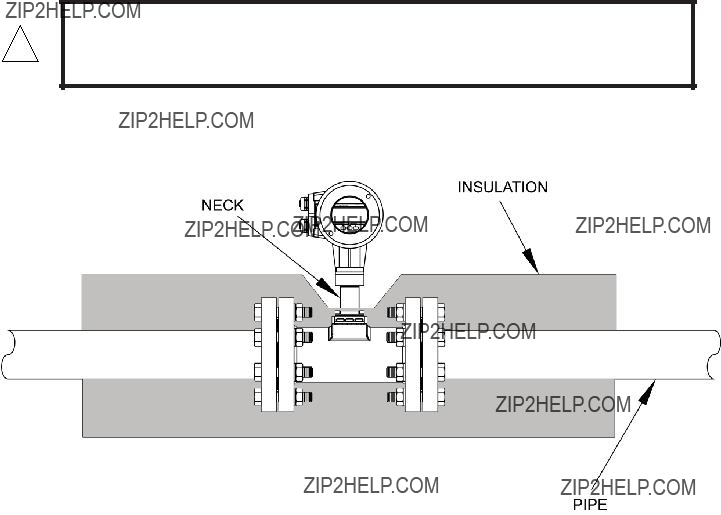
The drawing below illustrates the proper method for insulating the flow meter.
CAUTION
!Insulating the entire neck of the flow meter will increase heat transfer to the electronics enclosure and may in some cases cause premature failure of the electronics.
TABLE OF CONTENTS

SECTION 1.0: INTRODUCTION
We, at ONICON INCORPORATED, would like to thank you for purchasing our
1.1PURPOSE OF THIS GUIDE
The purpose of this guide is to provide installation and commissioning procedures and basic operating and servicing instructions for ONICON
WARNING
!Only qualified service personnel should attempt to install or service this equipment. Serious injury may result from the improper installation or use of this equipment.
1.2PRINCIPAL OF OPERATION
ONICON
1.3FEATURES AND SPECIFICATIONS
CONSTRUCTION
Meter body:
Casting: 316 stainless steel for diameters up to 4??? 304 stainless steel for 6??? and 8??? diameters
Shedder bar: Unalloyed titanium
Shedder bar seal: Ni plated Inconnel
Damper pin
Viton for,
Kalrez 4079 for,
Parofluor for steam,
Electronics enclosure:
Enclosure material:
Enclosure viewing window: Tempered glass,
UV blocking
CALIBRATION
Each meter undergoes a 5 point velocity calibration from
PROGRAMMING
Each meter is programmed at the factory based on application specific data provided by the customer. Field
ACCURACY
Volumetric flow
??1% of reading accuracy (??2% for ????? & smaller sizes)
Mass flow
??1.5% of reading accuracy (??2.5% for ????? & smaller sizes)
OPERATING TEMPERATURE RANGE
Media temperature
25?? to 464?? F
Ambient temperature
0?? to 132?? F
DISPLAY / USER INTERFACE
16x64 dot matrix LCD with 3 button keypad and magnetic pin programming
OUTPUT SIGNALS
Rate:
Supply voltage range:
Minimum load resistance: 100 ohms
Maximum load resistance is calculated as follows:
Total: Scaled output pulse, programmable
Optically isolated open collector, 0.5 hz maximum
Rating:
SUPPLY VOLTAGE:
PROCESS CONNECTIONS:
Standard: ANSI #300 flanges
Optional: ANSI #600 flanges
APPROVALS
Safety: Conforms to CE mark as per LVD, PED and EMC Directive
Enclosure: Conforms to IP 65 and IP 67

1.4ADDITIONAL REQUIRED MATERIALS
Installer is responsible for providing suitable flanges and fasteners to connect the meter to the process piping. In addition, most installations will also require one reducer, one expander, pipe supports and a sufficient length of straight pipe (pipe diameter = meter size) to meet the installation requirements outlined in this manual. Use of an optional flow rectifier may be required in cases where the available space is not sufficient to allow for proper upstream straight pipe run.
1.5WORKING ENVIRONMENT
ONICON
The ambient operating temperature range is 0?? to 132?? F.
1.6SERIAL NUMBER
The serial number for your
SECTION 2.0: UNPACKING
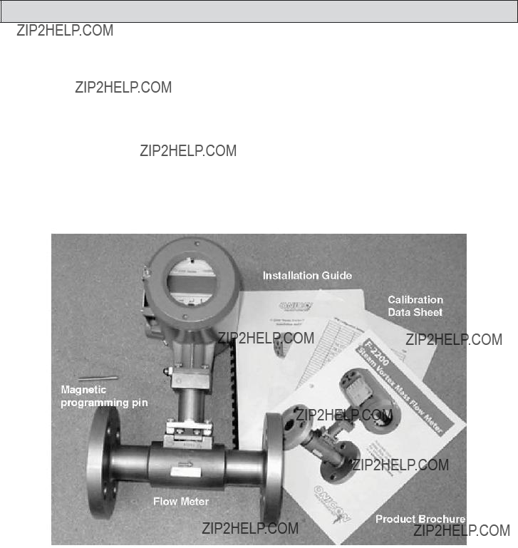
2.1 ENSURING THAT YOU HAVE RECEIVED EVERYTHING
Standard Documentation
Each ONICON flow meter is serialized and supplied with a comprehensive documentation package specifically prepared for this meter. It includes the following items. Please notify ONICON immediately if any discrepancies are found.
???Flow Meter
???The
???The Flow Meter Calibration Data Sheet
???Magnetic programming pin

SECTION 3.0: INSTALLATION INFORMATION
The
3.1SITE SELECTION
Careful attention in locating the point in the piping system where the flow meter will be installed will ensure accurate and reliable operation. When selecting an installation site, consider the criteria contained in Section 1.5 WORKING ENVIRONMENT, as well as the following:
CAUTION
!The installation guidelines presented below are minimum requirements for the proper operation of this flow meter.
3.1.1Flow Direction And Meter Position
The flow must always be in the direction of the arrow located on the meter body. This will orient the bluff side of the vortex shedder bar so that it faces the incoming f owl (i.e. the upstream side).
For vertical pipe runs, flow must always be in the upward direction. Consult the factory in the event that a downward flowing pipe is the only available location.
The diagrams shown below illustrate the correct meter orientation for vertical and horizontal pipe.
3.1.2Maximum Allowable Difference Between Inside Diameter Of Meter Body And The Connecting Pipe
The table below provides the maximum allowable difference between the diameter of the flow meter body and the connecting pipe.
Ensure that the bore of the locating pipes are smooth and without deposits, scaling, or welding beads.

3.1.3Straight, Unimpeded Inlet And Outlet Runs
D = Meter Size (Nominal diameter in inches)
With a flow straightener, the inlet pipe length may be reduced by 50%. For example, with a control valve upstream, the inlet length is 25D instead of 50D. The minimum inlet pipe length including the flow straightener must always be at least 12D.
3.1.4Minimizing Pipe Vibration
Pipe vibration caused, for example, by the action of pumps, valves, etc. will distort flow measurements, particularly at low flow velocities. To minimize the effects of vibration, support the pipeline on both sides of the meter in a direction perpendicular to both the pipeline and the shedder bar axis.

3.1.5Locating The Meter In A Pipline That Runs Parallel To A Wall
Wherever possible, the distance between the pipe centerline and the wall should be greater than 20???. This will allow for access to the electronics enclosure compartment where wire terminations are made. If adequate space is not available, first connect all the cables to the terminals in the connection compartment (power supply and outputs) and then run the wires to an intermediate junction box (also see Section 3.2) before installing the meter.
3.1.6State Of Medium
In all cases the meter requires a
3.1.6.1Liquid Applications
When operating with liquids, the meter requires a minimum downstream pressure to prevent cavitation. The formula used to determine the minimum downstream pressure is as follows:
Pds(bar_g) > =(2.9*DP) +
Where DP=pressure drop of the meter, in Bar, as determined by the ONICON sizing program and Ps=saturation pressure, in Bar, at the operating temperature.
For any fluid, a filter or strainer may be used to remove the solid particles. This is especially important for meter sizes below 1??? where a filter or a strainer is required.
3.1.6.2Steam Or Compressed Gas Applications
In case of steam or compressed gas, a moisture separator should be used 50D upstream of the meter if the dryness fraction is less than 95%.

3.2MECHANICAL INSTALLATION
3.2.1Orient The Display For Convenient Viewing
Both the electronics enclosure and the display itself can be rotated to four different orientations to change the viewing angle for the display. If necessary, this should be done before the meter is installed.
3.2.1.1Rotating the electronics enclosure
The electronics enclosure is attached to the meter body with (4) 5mm Allen head screws. To rotate the enclosure, you must first remove the screws and then carefully rotate the enclosure as needed. The interconnecting stem assembly is a conduit for wires that connect the sensors to the circuitry contained in the enclosure. Care must be taken to prevent these wires from being damaged when rotating the enclosure.

3.2.1.2Rotating the display
To rotate the display, first unscrew the cover using the special tool provided for this purpose. Once the cover is removed, the (4) Philips head screws that secure the display are exposed. To rotate the display, remove these screws and carefully move it to the desired position making certain that the interconnecting cable is not damaged in the process.
CAUTION
!??? Do not remove enclosure covers in any wet environment
???Keep dirt and debris out of electronics enclosure
???Keep threads lubricated (silicone based lubricant)
???Do not over tighten covers. Use special tool for removal only.
3.2.2
Meter sizes
3/8???, 1/2???, 3/4???, 1???, 1 1/2???, 2???, 3???, 4???, 6???, 8???
Pipe flanges
To ANSI: #300 standard, #600 optional
Gaskets are supplied with flanged units.
Center the flow meter by sight.
Check the flange connections for

3.3.2Temperature Measurements
ONICON
3.3WIRING TERMINATIONS
The standard
100 ohms minimum
SECTION 4.0: START UP AND TROUBLESHOOTING
4.1 START UP
When the power is applied to the
CAUTION
!Flow velocity through the meter should be increased gradually until full flow is achieved.
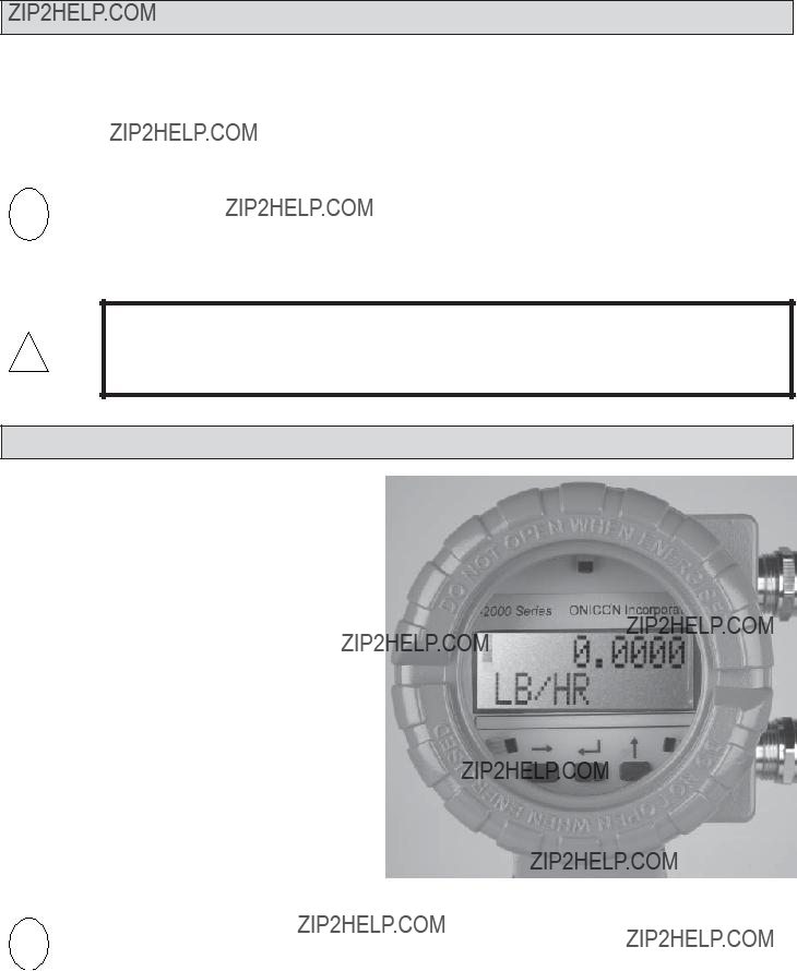
4.2MEASUREMENT MODE
In the measurement mode, the display indicates
There are two options for displaying data in the measurement mode. The display may be set to automatically scroll through each menu page or it may be set to manually step through the menu pages using the up arrow key to advance each page. Displays operating in the cyclic mode will advance through each page every 6 seconds.

4.3OPERATING THE DISPLAY
Please read the entire procedure before proceeding. Wiring diagrams are located in the Appendix. A worksheet for checking off the following steps and recording measured values is located on the next page.
key Hall
Effect Switch
Display page scroll (measurement mode)
There are 3 user interface switches located immediately below the display. Each switch performs a separate function. The table below describes the function of each switch. There are also 3 corresponding Hall Effect switches that perform the same functions. The Hall Effect switches may be activated without removing the display cover, using the magnet provided with the meter. Place the magnet against the cover in proximity to the Hall Effect switch to activate.
CAUTION
??? Do not remove enclosure covers in any wet environment.
!??? Keep dirt and debris out of electronics enclosure.
???Keep threads lubricated (silicone based lubricant).
???Do not over tighten covers. Use special tool for removal only.

4.4ERROR HANDLING
The meter can detect errors in either the test or the measurement modes. When in the measurement mode, a blinking vertical bar will appear in the top left corner of the display indicating an error has been detected. If the error reporting function is enabled, error messages will be displayed as separate menu pages. The first line of the error menu page indicates the total number of errors and the second line displays the error message. Measurement mode error messages are listed below.

4.5 TROUBLESHOOTING HINTS
SECTION 5.0: FLOW STRAIGHTENER FOR VORTEX FLOW METERS
DESCRIPTION
The optional flow straightener accessory for ONICON
Use of a flow straightener significantly reduces the upstream straight pipe length requirement for ONICON Vortex Flow Meters.
The size of the straightener should always match the meter size (as opposed to the original pipe size).
The flow straightener is made of 304/A 351 CF8 stainless steel.
TABLE 1 - ALL DIMENSIONS SHOWN IN INCHES

ONICON
 ECCENTRIC REDUCER, NOTE 2
FLOW STRAIGHTENER, NOTE 3
300# ANSI FLANGE
(600# ANSI FLANGE OPTNL)
5 DIAMETERS
MINIMUM DOWNSTREAM PIPE RUN
REQUIRED DIMENSIONS FOR INSTALLATIONS WITH FLOW STRAIGHTENER
NOTES
1.Consult ONICON for meter size and applicable meter pipe run for each application. Install according to manufacturer???s recommendations.
2.Provide eccentric reducer and expander when required.
3.Provide ???ow straightener when required to meet recommended minimum upstream pipe run requirements.
4.Flanges provided by contractor. Recessed ???anges are required for wafer ???ow straightener installation.