Installation and Assembly - Unistrut adapter for truss ceiling Model: ACC 550
IMPORTANT! Read entire instruction sheet before you start installation and assembly.
R
Before you start make sure all parts listed are included with your product.
This product must be installed by a qualified, professional installer.
MAXIMUM LOAD CAPACITY: 250 lb (114 kg)
Parts List
Some parts may appear slightly different than illustrated.
 Attach mounting body (A) to alignment plate (B)
  using two M10 socket head screws (D) and attachment plate (C).
D
D

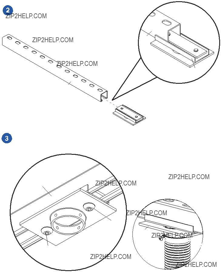
 Slide unistrut adapter assembly onto
 unistrut. Unistrut will slide in between alignment plate (B) and attachment plate (C).
unistrut
C
B
unistrut
unistrut adapter assembly
 Once unistrut adapter assembly is in desired position, tighten M10 socket head screws (D). When attaching the
  mounting body (A) to flush mount tube or extension column. Tighten at least four complete turns ending with one of the small threaded holes aligned with slot in the end of flush mount tube. Insert and tighten one security screw (E) shown below right.
unistrut
unistrut
 unistrut adapter assembly
D
D
A
E 
If unistrut is closed on both

 ends place attachment plate (C) inside unistrut. Attach alignment plate (B) and mounting body (A) to attachment plate (C) using two M10 socket head screws (D).
unistrut
C
C
C
B
unistrut
A
D
D
?? 2003 Peerless Industries, Inc. All rights reserved.
Peerless is a registered trademark of Peerless Industries, Inc.