Installation and Assembly:
Video Wall Mount
Model:
Installation and Assembly:
Video Wall Mount
Model:

NOTE: Read entire instruction sheet before you start installation and assembly.
 WARNING
???Do not begin to install your Peerless product until you have read and understood the instructions and warnings contained in this Installation Sheet. If you have any questions regarding any of the instructions or warnings, for US customers please call Peerless customer care at
???This product should only be installed by someone of good mechanical aptitude, has experience with basic building construction, and fully understands these instructions.
???Make sure that the supporting surface will safely support the combined load of the equipment and all attached hardware and components.
???Never exceed the Maximum Load Capacity. See page one.
???If mounting to wood wall studs, make sure that mounting screws are anchored into the center of the studs. Use of an "edge to edge" stud finder is highly recommended.
???Always use an assistant or mechanical lifting equipment to safely lift and position equipment.
???Tighten screws firmly, but do not overtighten. Overtightening can damage the items, greatly reducing their holding power.
???This product is intended for indoor use only. Use of this product outdoors could lead to product failure and personal injury.
???This product was designed to be installed on the following wall construction only;
Tools Needed for Assembly
???stud finder ("edge to edge" stud finder is recommended)
???phillips screwdriver
???drill
???5/16" (8 mm) bit for concrete and cinder block wall
???5/32" (4 mm) bit for wood stud wall
???level
Accessories
???

Vertical Spacing Location
DISPLAY
HEIGHT
H
X - 10.25 + (.938 OR 1.688) = (Y1 OR Y2)
Horizontal Spacing Location
If
To determine edge of second mount, add (Z) to edge of first mount.
WIDTH
DISPLAY WIDTH
Horizontal Location
DISPLAY WIDTH - (35) = Z (SPACING BETWEEN MOUNTS)

D
E F G  H
H  I
I  J K
J K 
L

Installation to Wall Stud
 WARNING
???Installer must verify that the supporting surface will safely support the combined load of the equipment and all attached hardware and components.
???Tighten wood screws so that wall plate is firmly attached, but do not overtighten. Overtightening can damage the screws, greatly reducing their holding power.
???Never tighten in excess of 80 in. ??? lb (9 N.M.).
???Make sure that mounting screws are anchored into the center of the stud. The use of an "edge to edge" stud finder is highly recommended.
???Hardware provided is for attachment of mount through standard thickness drywall or plaster into wood studs.
Installers are responsible to provide hardware for other types of mounting situations.
plate, and mark the center of the four mounting holes. Make sure that the mounting holes are on the stud center line. Drill four 5/32" (4 mm) dia. holes
STUD
B
E

Installation to Solid Concrete or Cinder Block
 WARNING
???When installing Peerless wall mounts on cinder block, verify that you have a minimum of
???Concrete must be 2000 psi density minimum. Lighter density concrete may not hold concrete anchor.
???Make sure that the wall will safely support four times the combined load of the equipment and all attached hardware and components.
Make sure that video wall plate (B) is level, use it
1 as a template to mark four mounting holes. Drill four
5/16??? (8 mm) dia. holes to a minimum depth of 2.5??? (64 mm). Insert anchors (F) in holes flush with wall as shown (right). Place video wall mount assembly over anchors and secure with four #14 x 2.5??? screws (E). Level, then tighten all fasteners.
F
solid concrete
cinder block
 WARNING
???Tighten screws so that wall plate is firmly attached, but do not overtighten. Overtightening can damage screws, greatly reducing their holding power.
???Never tighten in excess of 80 in. ??? lb (9 N.M.).
???Always attach concrete expansion anchors directly to
???Never attach concrete expansion anchors to concrete covered with plaster, drywall, or other finishing material. If mounting to concrete surfaces covered with a finishing surface is unavoidable, the finishing surface must be counterbored as shown below. Be sure concrete anchors do not pull away from concrete when tightening screws. If plaster/drywall is thicker than 5/8" (16 mm), custom fasteners must be supplied by installer
E B
F
Drill holes and insert anchors (F).
E 
 F
F
Place wall plate (B) over anchors (F) and secure with screws (E).
3
Tighten all fasteners.
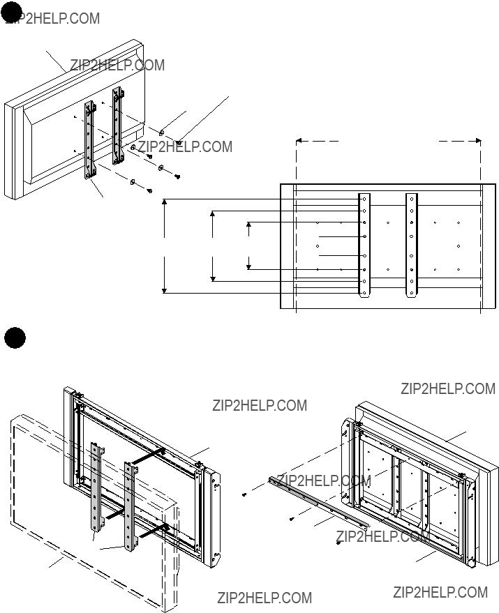
Attaching Adapter Brackets to Display
I or J
G
MAX
MIN
CHANNEL


 A
A
DISPLAY
C
DISPLAY
FIGURE 3.1
D

K A
BACK VIEW
FIGURE 3.2

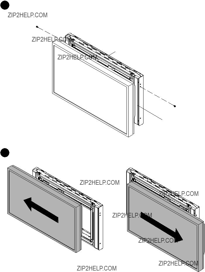
Horizontal Display Position
Screen and adapter brackets can slide along rail to position screen horizontally.
OPTIONAL GUIDE: When positioning adapter brackets (C) make sure outside edge of adapter bracket is in notch on display carriage as shown in detail 1.
OUTSIDE EDGE OF
ADAPTER BRACKET
NOTCH
 C
C
DETAIL 1
Installing Carriage Assembly to Wall Plate
DISPLAY
SLOT
DETAIL 2
B
H
A
6 Horizontal Display Adjustment
Adapter Brackets (C) and display can be adjusted horizontally.

Carriage Assembly Adjustment
 Turn knob CLOCKWISE to tighten
Turn knob
?? 2010, Peerless Industries, Inc. All rights reserved. All other brand and product names are trademarks or registered trademarks of their respective owners.