EQ??? 31FX
31 Band Professional Graphic Equalizer
Owner???s Manual
EQ??? 31FX
31 Band Professional Graphic Equalizer
Owner???s Manual

Intended to alert the user to the presence of uninsulated ???dangerous voltage??? within the product???s enclosure that may be of sufficient magnitude to constitute a risk of electric shock to persons.
Intended to alert the user of the presence of important operating and maintenance (servicing) instructions in the literature accompanying the product.
CAUTION: Risk of electrical shock ??? DO NOT OPEN!
CAUTION: To reduce the risk of electric shock, do not remove cover. No user serviceable parts inside. Refer servicing to qualified service personnel.
WARNING: To prevent electrical shock or fire hazard, do not expose this appliance to rain or moisture. Before using this appliance, read the operating guide for further warnings.
Este s??mbolo tiene el prop??sito, de alertar al usuario de la presencia de ???(voltaje) peligroso??? que no tiene aislamiento dentro de la caja del producto que puede tener una magnitud suficiente como para constituir riesgo de corrientazo.
Este s??mbolo tiene el prop??sito de alertar al usario de la presencia de instruccones importantes sobre la operaci??n y mantenimiento en la literatura que viene con el producto.
PRECAUCION: Riesgo de corrientazo ??? No abra.
PRECAUCION: Para disminu??r el riesgo de corrientazo, no abra la cubierta. No hay piezas adentro que el usario pueda reparar. Deje todo mantenimiento a los t??cnicos calificados.
ADVERTENCIA: Para evitar corrientazos o peligro de incendio, no deje expuesto a la lluvia o humedad este aparato Antes de usar este aparato, Iea m??s advertencias en la gu??a de operaci??n.
Ce symbole est utilis?? pur indiquer ?? l???utilisateur la pr??sence ?? l???int??rieur de ce produit de tension non- isol??e dangereuse pouvant ??tre d???intensit?? suffisante pour constituer un risque de choc ??lectrique.
Ce symbole est utilis?? pour indiquer ?? l???utilisateur qu???il ou qu???elle trouvera d???importantes instructions sur l???utilisation et l???entretien (service) de l???appareil dans la litt??rature accompagnant le produit.
ATTENTION: Risques de choc ??lectrique ??? NE PAS OUVRIR!
ATTENTION: Afin de r??duire le risque de choc ??lectrique, ne pas enlever le couvercle. Il ne se trouve ?? l???int??rieur aucune pi??ce pouvant ??tre repar??e par l???utilisateur. Confier I???entretien ?? un personnel qualifi??.
AVERTISSEMENT: Afin de pr??venir les risques de d??charge ??lectrique ou de feu, n???exposez pas cet appareil ?? la pluie ou ?? l???humidit??. Avant d???utiliser cet appareil, lisez les avertissements suppl??mentaires situ??s dans le guide.
Dieses Symbol soll den Anwender vor unisolierten gef??hrlichen Spannungen innerhalb des Geh??uses warnen, die von Ausreichender St??rke sind, um einen elektrischen Schlag verursachen zu k??nnen.
Dieses Symbol soll den Benutzer auf wichtige Instruktionen in der Bedienungsanleitung aufmerksam machen, die Handhabung und Wartung des Produkts betreffen.
VORSICHT: Risiko ??? Elektrischer Schlag! Nicht ??ffnen!
VORSICHT: Um das Risiko eines elektrischen Schlages zu vermeiden, nicht die Abdeckung enfernen. Es befinden sich keine Teile darin, die vom Anwender repariert werden k??nnten. Reparaturen nur von qualifiziertem Fachpersonal durchf??hren lassen.
ACHTUNG: Um einen elektrischen Schlag oder Feuergefahr zu vermeiden, sollte dieses Ger??t nicht dem Regen oder Feuchtigkeit ausgesetzt werden. Vor Inbetriebnahme unbedingt die Bedienungsanleitung lesen.
2

ENGLISH
Congratulations on purchasing the EQ??? 31FX! With its introduction, Peavey engineers have taken graphic equalizers to the next level. The EQ??? 31FX offers 31 bands of 1/3 octave filters featuring superior constant ???Q??? devices. LED indicators are located in the slider of the frequency bands to identify the presence of a high energy signal (usually feedback). This sophisticated feed- back detector system will allow you to quickly identify and remove feedback. It works like this: When the feedback detection circuit detects the frequency band with the most energy, it causes the LED in the slider of the associated frequency band to illuminate. By moving the fader downward for that band, the likelihood of feedback is reduced/eliminated. Most use the EQ 31FX in one of two ways: 1. To catch and reduce/eliminate feedback
After the system is set up, bring up the microphone levels slowly. As they start to feed back, note the LED activity on the EQ 31FX feedback bands. Move the faders to decrease the ???identified??? bands. Now you have eliminated a high percentage of potential feedback problems, before the per- formance even begins! Note: It is not uncommon for feedback to be active over several frequency bands. Also, go easy when making fader adjustments since extreme movements will affect your per- formance and be counterproductive.
OPERATION NOTE
This equalizer is designed to provide room equalization, feedback control and system tone control. No amount of equalization will correct an acoustically bad room/mic/speaker arrangement or completely correct the response of a poor loudspeaker. Always begin with all sliders in the ???0??? position and avoid excessively cutting large segments of the audio passband, which would limit the system???s dynamic range. Exercise caution when attempting to boost equalization below
FRONT PANEL
FRONT PANEL FEATURES:
BYPASS SWITCH (1)
In Bypass mode (switch in), the input signal is routed directly to the output and is unaffected by all front panel controls except the low and high cut filters.
BYPASS LED (2)
This LED will illuminate when the Bypass switch is in the ???in??? position, indicating that the EQ and
3

gain controls are bypassed.
LOW CUT (3)
A high pass filter, continuously variable from 5 Hz to 200 Hz. Low frequency
HIGH CUT (4)
A low pass filter, continuously variable from 5 kHz to 35 kHz. High frequency
LED LEVEL METER (5)
This multicolored LED ladder indicates output level.
GAIN (6)
Calibrated control for regulating overall gain of the equalizer section. Unity gain throughout the signal chain may be maintained by recovering lost signal at this point. Example: Assume the equalization process has introduced a signal loss of
EQUALIZER SECTION (7)
31 bands of 1/3 octave filters. The filters are constant ???Q??? devices, located at ISO center frequencies. Effective equalization range is from 20 Hz to 20 kHz. Maximum cut or boost per frequency is 15 dB.
AUTOMATIC FEEDBACK LOCATING LEDs (8)
When feedback occurs, the LED of the frequency band that is feeding back will illuminate indicating feedback in that band. The LED will remain illuminated for a few seconds even after the feedback is gone. This is to allow you to see where the feedback is if the feedback goes away before any correction is made. If there is no feedback occurring, the LED of the frequency band with the most energy in it will illuminate. Just because the LED is illuminated does not mean that there is feedback occurring. For best performance of the automatic feedback locating system, use an input signal of
0 dB (1V RMS).
POWER SWITCH (9)
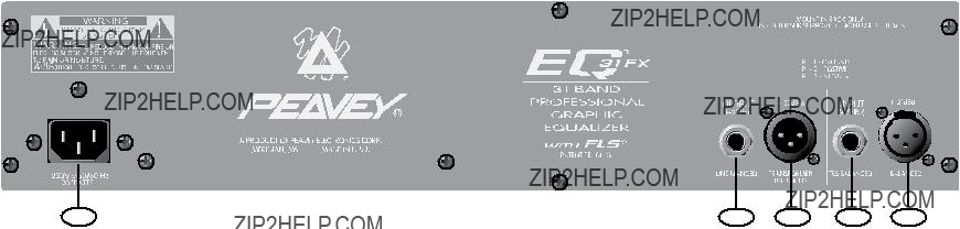
REAR PANEL
Used to turn AC mains power on or off.
INPUT XLR (1)
4
A
INPUT 1/4" (2)
1/4"
OUTPUT XLR (3)
A transformer balanced, male XLR output provides
OUTPUT 1/4" (4)
1/4" phone jack is provided for unbalanced output termination.
LINE CORD (120V Products only) (5)
We have incorporated a
Power requirements:
Domestic: 120VAC / 60 Hz / 20 W.
Export: 230VAC / 50/60 Hz / 20 W.
NOTE: CAUTION: TO PREVENT ELECTRIC SHOCK, MATCH WIDE BLADE OF PLUG TO WIDE SLOT,
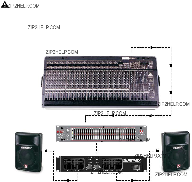
EQ??? 31FX Application:
Mono send from Mixer to external
EQ/Power Amp combination.
 Main Balanced Output
EQ 31FX
 Balanced Input
EQ 31FX Balanced Output
Parallel Patch
Balanced Input CH 2
 CS800S Balanced Input CH 1
5
SPECIFICATIONS
Frequency Response:
+/- 1 dB 20 Hz to 20 kHz
Distortion:
.005% 20
Input Impedance:
Balanced 20 k Ohms (Equal impedance to ground)
Output Impedance:
330 Ohms
Maximum Input Level:
+21 dBu (8.6 V RMS)
Maximum Output Level:
+27 dBu (17 V RMS)
Nominal Input Level:
0 dBV (1 V RMS)
Nominal Output Level:
0 dBV (1 V RMS)
Input Headroom:
Nominal 21 dBu
Output Headroom:
27 dBu
Output Noise:
EQ in bypass:
EQ in, all flat:
Filter Frequencies:
20, 25, 32, 40, 50, 63, 80, 100, 125, 160,
200, 250, 315, 400, 500, 630, 800, 1 k,
1.25 k, 1.6 k, 2 k, 2.5 k, 3.15 k, 4 k, 5 k, 6.3 k, 8 k, 10 k, 12.5 k, 16 k, and 20 kHz
Filter Q:
4.77
Maximum Boost and Cut Filter:
+/- 15 dB
Maximum Boost and Cut Gain (WideBand
Gain):
+/- 15 dB
Low Cut Filter:
12 dB Per Octave
Frequency:
Min: 5 Hz
Max: 200 Hz
High Cut Filter:
12 dB Per Octave
Frequency:
Min: 5 kHz
Max: 35 kHz
All specifications are typical unless otherwise noted. 0 dBV=1 Volt. All specifications are referenced to nominal output level (0 dBV) unless otherwise stated. All measurements are wideband 20 Hz to 20 kHz unless otherwise stated. NOTE: All specs measured at 1V RMS input and unbalanced output. All sliders at mid position, all switches out unless otherwise noted. Due to our efforts for constant improvement, features and specifications listed herein are subject to change without notice.
6

ESPA??OL
??Lo felicitamos por adquirir el ecualizador EQ??? 31 FX! Con la presentaci??n de este equipo, los ingenieros de Peavey han creado una nueva generaci??n de ecualizadores gr??ficos. El ecualiza- dor EQ??? 31 FX ofrece 31 bandas de filtros de 1/3 de octava con dispositivos de ???Q??? (selectividad) constante de calidad superior. Los LED indicadores se encuentran en el control deslizante de las bandas de frecuencia para identificar la presencia de se??ales de alta energ??a (normalmente, son se??ales de retroalimentaci??n). Este sofisticado sistema detector le permitir?? identificar y eliminar r??pidamente la retroalimentaci??n. Funciona de la siguiente manera: Cuando el sistema de detecci??n de retroalimentaci??n identifica la banda de frecuencia de mayor energ??a, se enciende el LED del control deslizante de la banda de frecuencia correspondiente. Esto permite reducir o eliminar la probabilidad de retroalimentaci??n desplazando el atenuador de esa banda. La mayor??a de los usuar- ios utilizan el ecualizador EQ 31FX de dos maneras: 1. Para captar y reducir/eliminar ???al instante??? la retroalimentaci??n en un sistema de amplificadores. 2. Para determinar las bandas de frecuencia susceptibles de retroalimentaci??n ANTES de utilizar el sistema de amplificadores, a fin de eliminar- las anticipadamente.
Despu??s de configurar el sistema, aumente lentamente los niveles de micr??fono. Cuando comience la retroalimentaci??n, observe la actividad de los LED indicadores de las bandas de fre- cuencia del ecualizador EQ 31 FX. Desplace los atenuadores para reducir las bandas ???identifica- das???. De esta forma usted puede eliminar un alto porcentaje de problemas potenciales de retroali- mentaci??n, ??antes de utilizar el sistema de amplificadores! Nota: Es com??n que la retroalimentaci??n ocurra simult??neamente en varias bandas de frecuencia. Proceda lentamente al ajustar los atenua- dores, pues los movimientos r??pidos afectan la calidad de la reproducci??n y resultan contraprodu- centes.
NOTA SOBRE LA OPERACI??N
El ecualizador est?? dise??ado para proporcionar ecualizaci??n ambiental y controles de retroali- mentaci??n y tono en sistemas de amplificadores. Ninguna ecualizaci??n puede compensar una com- binaci??n o distribuci??n ac??sticamente deficiente de sala, micr??fonos y altavoces, como tampoco cor- regir completamente la respuesta de un altavoz deficiente. Comience siempre con los controles deslizantes en la posici??n ???0??? y evite anular excesivamente segmentos largos de la banda pasante de audio, porque se limitar??a la gama din??mica del sistema. Sea cuidadoso cuando intente reforzar la ecualizaci??n por debajo de la frecuencia de corte de los altavoces. Las cajas ac??sticas de refuer- zo de sonido t??picas no est??n dise??adas para funcionar a 20 Hz y podr??an da??arse los transduc- tores.
Consulte los diagramas del panel delantero en la secci??n de ingl??s de este manual.
CARACTER??STICAS DEL TABLERO FRONTAL
INTERRUPTOR DE DERIVACI??N (1)
En el modo de derivaci??n o desv??o (interruptor hacia adentro), la se??al de entrada se dirige directa- mente a la salida y no es afectada por los controles del panel frontal, excepto los filtros de corte de frecuencias bajas y altas.
LED DE DERIVACI??N (2)
Este LED se enciende cuando el interruptor de derivaci??n est?? hacia adentro, para indicar que se puentean los controles de ecualizaci??n y ganancia.
CORTE DE BAJA FRECUENCIA (3)
Filtro pasaaltos, variable continuamente de 5 Hz a 200 Hz. La atenuaci??n progresiva a baja frecuen- cia es de 12 dB por octava. Ajuste este control a un valor aproximado a la frecuencia de corte inferi- or del sistema de altavoces.
7
CORTE DE ALTA FRECUENCIA (4)
Filtro pasabajos, variable continuamente de 5 a 35 kHz. La atenuaci??n progresiva a alta frecuencia es de 12 dB por octava. Ajuste este control a un valor aproximado a la frecuencia de corte superior del sistema.
LED INDICADORES DE NIVEL (5)
Esta escalera de LED multicolores indica el nivel de la se??al de salida.
GANANCIA (6)
Control calibrado para regular la ganancia total de la secci??n de ecualizaci??n. Puede mantenerse una ganancia unitaria a lo largo de la cadena de se??al recuperando en este punto el nivel de se??al perdido. Por ejemplo, supongamos que el proceso de ecualizaci??n introdujo una p??rdida de se??al de
+6 dB para mantener la ganancia unitaria del ecualizador (es decir, el nivel de salida es igual al nivel de entrada).
SECCI??N DE ECUALIZACI??N (7)
Ofrece 31 bandas de filtros de 1/3 de octava. Los filtros son dispositivos de ???Q??? (selectividad) con- stante, calibrados a las frecuencias centrales definidas por las normas ISO. La gama de ecual- izaci??n efectiva es de 20 Hz a 20 kHz. El nivel de corte y refuerzo m??ximo de cada frecuencia es 15 dB.
LED DE LOCALIZACI??N AUTOM??TICA DE RETROALIMENTACI??N (8)
Cuando se produce retroalimentaci??n, se enciende el LED de la banda retroalimentada para indicar la presencia de retroalimentaci??n en dicha banda. El LED permanece iluminado durante algunos segundos, a??n despu??s de que la retroalimentaci??n desaparece. La finalidad de esta funci??n es permitir que el usuario vea d??nde ocurri?? la retroalimentaci??n en caso de que ??sta desaparezca antes de que sea posible efectuar correcciones. Si no se produce retroalimentaci??n, se enciende el LED de la banda de frecuencia de mayor energ??a. El solo hecho de que el LED se encienda no sig- nifica que exista retroalimentaci??n. Para optimizar el funcionamiento del sistema de localizaci??n autom??tica, utiliza una se??al de entrada de 0 dB (1 Vef).
INTERRUPTOR DE ENCENDIDO (9)
Se utiliza para encender y apagar el equipo.
TABLERO TRASERO
CARACTER??STICAS DEL TABLERO TRASERO
ENCHUFE XLR DE ENTRADA (1)
Enchufe hembra XLR de tres terminales provisto para terminaci??n de entrada equilibrada electr??ni-
8

camente (terminal 2 positivo, terminal 3 negativo).
ENTRADA DE 1/4 PULG. (2)
Enchufe hembra de tipo de punta, anillo y manguito de 1/4 pulg. (estereof??nico) que proporciona una entrada equilibrada cuando se usa con enchufes estereof??nicos de 1/4 pulg. (TRS) y cables blindados de dos conductores. Cuando se usa con un enchufe fonogr??fico monof??nico de 1/4 pulg., la entrada no es equilibrada.
ENCHUFE XLR DE SALIDA (3)
Salida XLR macho equilibrada por transformador que proporciona balance de l??nea para otros equi- pos de audio (amplificadores de potencia, etc.). La salida equilibrada se recomienda para el rechazo de zumbido, ruido e interferencia externa (terminal 2 positivo, terminal 3 negativo).
SALIDA DE 1/4 PULG. (4)
Enchufe hembra de 1/4 pulg. para terminaci??n de salida no equilibrada.
CORD??N DE ALIMENTACI??N (productos para 120 V ??nicamente) (5)
Hemos incorporado un cable bifilar para la alimentaci??n el??ctrica del ecualizador EQ 31FX.
Requisitos de energ??a el??ctrica:
Estados Unidos: 120 VCA, 60 Hz, 20 W
Otros pa??ses: 230 VCA, 50 ?? 60 Hz, 20 W
PRECAUCI??N: PARA EVITAR DESCARGAS EL??CTRICAS, HAGA COINCIDIR EL
TERMINAL ANCHO DEL ENCHUFE CON LA RANURA ANCHA E INSERTE EL ENCHUFE
9
XR??? 31FX ESPECIFICACIONES
COMPLETAMENTE.
Respuesta de frecuencia:
??1 dB de 20 Hz a 20 kHz
Distorsi??n:
0,005% de 20 Hz a 20 kHz
Impedancia de entrada:
20 k??, equilibrada (igual impedancia con respecto a tierra)
Impedancia de salida:
330 ??
M??ximo nivel de entrada:
+21 dBu (8,6 Vef)
M??ximo nivel de salida:
+27 dBu (17 Vef)
Nivel de entrada nominal:
0 dBV (1 Vef)
Nivel de salida nominal:
0 dBV (1 Vef)
Tolerancia de m??ximo nivel de se??al de entrada:
Nominal 21 dBm
Tolerancia de m??ximo nivel de se??al de salida:
27 dBu
Ruido de salida:
Ecualizaci??n en modo de derivaci??n:
Frecuencias de filtros:
20; 25; 32; 40; 50; 63; 80; 100; 125; 160; 200;
250; 315; 400; 500; 630; 800; 1 kHz; 1,25 kHz;
1,6 kHz; 2 kHz; 2,5 kHz; 3,15 kHz; 4 kHz; 5 kHz; 6,3 kHz; 8 kHz; 10 kHz; 12,5 kHz; 16 kHz y
20 kHz.
Q (selectividad) de filtros:
4,77
Filtros de refuerzo y corte (niveles m??ximos):
??15 dB
Ganancias de refuerzo y corte m??ximas (ganancia de banda ancha):
??15 dB
Filtros de corte de baja frecuencia:
12 dB por octava
Frecuencias:
M??nima: 5 Hz
M??xima: 200 Hz
Filtros de corte de alta frecuencia:
12 dB por octava
Frecuencias:
M??nima: 5 kHz
M??xima: 35 kHz
A menos que se especifique lo contrario, todas las especificaciones corresponden a valores t??pi- cos; se considera que 0 dBV = 1 V; todas las especificaciones est??n referidas al nivel de sali- da nominal (0 dBV); todas las mediciones corre- sponden a una banda ancha de 20 Hz a 20 kHz. NOTA: A menos que se especifique lo contrario, todas las especificaciones corresponden a un nivel de entrada de 1 Vef, con salida no equili- brada, con todos los controles deslizantes en la posici??n central y todos los interruptores hacia afuera. Debido a nuestros constantes esfuerzos por mejorar los sistemas, las caracter??sticas y las especificaciones indicadas en este folleto est??n sujetas a cambios sin previo aviso.
10
FRAN??AIS
Nous vous f??licitons pour l???achat de cet EQ??? 31FX! L???EQ??? 31FX dispose de 31 filtres 1/3 d???octave de qualit?? sup??rieure, ?? ???Q??? constant. Des LEDs situ??es sur les curseurs des poten- tiom??tres rectilignes permettent de rep??rer la pr??sence d???un signal haute ??nergie sur la bande de fr??quences concern??e (g??n??ralement indiquant un feedback). Ce d??tecteur de feedback vous per- mettra de rapidement identifier et ??liminer tout larsen. Lorsque le syst??me d??tecte la bande de fr??quence ayant la plus haute ??nergie, la LED du slider qui lui correspond s???illumine. En d??pla??ant son curseur vers la bas, la possibilit?? de feedback est diminu??e/??limin??e. Le EQ 31FX peut ??tre utili- s?? de deux mani??res diff??rentes: 1. Pour rep??rer et diminuer/??liminer le larsen en temps r????l pen- dant une performance. 2. Pour d??terminer avant la performance quelles bandes de fr??quences sont susceptibles d???entrer en feedback et ??liminer le probl??me ?? l???avance.
Une fois le syst??me de sonorisation install??, montez progressivement les niveaux des micros.
Lorsqu???un larsen appara??t, rep??rez l???activation des LED sur les bandes du EQ 31FX. D??placez les curseurs pour diminuer le gain des bandes identifi??es. Vous ??liminez ainsi un grand pourcentage des probl??mes de larsen potentiels avant m??me que ne commence le show. Note: Il n???est pas rare qu???un larsen apparaisse sur diff??rentes bandes de fr??quences en m??me temps. En cons??quence, ??vitez les r??glages excessifs de vos faders qui pourraient nuire ?? votre performance et ??tre
conseil d???utilisation
Cette unit?? est con??ue pour ??qualiser une pi??ce, contr??ler le feedback est ajuster la tonalit?? d???un syst??me. Aucune ??qualisation ne corrigera un mauvais arrangement ou une mauvaise disposi- tion des divers ??l??ments acoustiques (micros, enceintes et salle), ni la r??ponse d'un
CARACT??RISTIQUES DU PANNEAU AVANT s??lecteur BYPASS (1)
En mode Bypass (s??lecteur engag??), le signal d???entr??e est dirig?? directement vers la sortie et n???est pas affect?? par les contr??les de fa??ade except??s les filtres low et high cut.
LED de BYPASS (2)
Cette LED s???illuminera lorsque le s??lecteur Bypass sera engag??, indiquant que l???EQ et le contr??le de gain ne sont pas effectifs.
FILTRE LOW CUT (3)
Filtre
FILTRE HIGH CUT (4)
Filtre
11

VU???METRE A LED (5)
Cette ??chelle multicolore indique le niveau de sortie.
GAIN (6)
Contr??le calibr?? pour le r??glage du gain g??n??ral de la section EQ. Le gain unitaire de la cha??ne de traitement du signal peut ??tre r??tabli gr??ce ?? ce contr??le. Ainsi, si le r??glage d?????galisation induit une perte de
SECTION d???EQUALIsation (7)
31 filtres de bandes de 1/3 d???octave. Les filtres poss??dent un ???Q??? constant et sont centr??s sur les fr??quences standard ISO. Le registre effectif d?????qualisation s?????tend de 20 Hz ?? 20 kHz. L???att??nuation et le gain maximum par bande sont de 15 dB.
LEDs de localisation automatique du FEEDBACK (8)
A l'apparition du feedback, la LED correspondant ?? la bande de fr??quence concern??e s'illumine. Si le feedback est fort et intermittent, la LED restera allum??e quelques secondes apr??s sa disparition, vous permettant de rep??rer la bande de fr??quence fautive et d'ajuster votre ??qualiseur. Cela vous permet de voir o?? se situe le feedback s'il dispara??t avant qu'une correction n'ait pu ??tre effectu??e. S'il n'y a pas de feedback, la LED correspondant ?? la bande de fr??quence pr??sentant la plus haute
??nergie s'illuminera. Une LED allum??e ne signifie pas obligatoirement la pr??sence d'un feedback. Pour une performance optimum du syst??me de localisation du feedback, utilisez un signal d???entr??e ??
0 dB (1V RMS).
INTERRUPTEUR DE MISE SOUS TENSION (9)
Pressez l'interrupteur pour le mettre en position ???ON???. Une LED verte s'illumine indiquant la mise sous tension de l'unit??.
CARACT??RISTIQUES DU PANNEAU ARRI??RE:
PANNEAU ARRI??RE
entr??e XLR (1)
Prise XLR femelle sym??tris??e ??lectroniquement (pin 2 positif, pin 3 negatif).
entr??e jack (2)
Prise Jack TRS (st??r??o) fournissant une entr??e sym??trique avec un prise Jack st??r??o (TRS) et un c??ble ?? deux conducteurs + blindage. Utilis?? avec une prise Jack mono, l???entr??e est asym??trique.
sortie XLR (3)
Une sortie m??le XLR fournit une sortie ligne sym??trique aux autres ??l??ments de l?????quippement sono
(amplis de puissance, etc...) Les sorties sym??triques sont recommand??es pour une r??jection maxi- mum des souffles, bruits de fond et autres interf??rences ext??rieures (pin 2 positif, pin 3 negatif). sortie jack (4)
12
Prise Jack pour sortie asym??trique.
Alimentation n??cessaire:
230VAC / 50/60 Hz / 20 W.
XR??? 31FX SPECIFICATIONS
R??ponse fr??quentielle:
+/- 1 dB 20 Hz to 20 kHz
Distorsion:
.005% 20
Imp??dance d???entr??e:
Sym??trique: 20 k Ohms (Imp??dance ?? la masse
??quivalente)
Imp??dance de sortie:
330 Ohms
Niveau maximum d'entr??e:
+21 dBu (8.6 V RMS)
Niveau de sortie maximum:
+27 dBu (17 V RMS)
Niveau d'entr??e nominal:
0 dBV (1 V RMS)
Niveau de sortie nominal:
0 dBV (1 V RMS)
Headroom en entr??e:
21 dBu Nominal
Headroom en sortie:
27 dBu
Bruit en sortie:
EQ en bypass:
EQ engag??, tout ?? 0:
Fr??quences des filtres:
20, 25, 32, 40, 50, 63, 80, 100, 125, 160, 200, 250, 315, 400, 500, 630, 800, 1 k, 1.25 k, 1.6 k, 2 k, 2.5 k, 3.15 k, 4 k, 5 k,
6.3 k, 8 k, 10 k, 12.5 k, 16 k, et 20 kHz
Facteur Q des filtres:
4.77
Boost et Cut maximum des filtres:
+/- 15 dB
Boost et Cut maximum du Gain g??n??ral:
+/- 15 dB
Filtre
12 dB Par Octave
Fr??quence:
Min: 5 Hz
Max: 200 Hz
Filtre
12 dB Per Octave
Fr??quence:
Min: 5 kHz
Max: 35 kHz
Toutes les caract??ristiques sont typiques sauf indications. 0 dBV=1 Volt. Toutes les caract??ris- tiques sont donn??es pour un niveau de sortie nominal (0 dBV) sauf indications. Toutes les mesures s???appliquent pour la bande passante de 20 Hz ?? 20 kHz sauf indications.
NOTE: Caract??ristiques mesur??es ?? 1V RMS ?? l???entr??e asym??trique. Tous les curseurs en posi- tion m??diane et s??lecteurs d??sengag??s sauf indi- cations. Etant donn??s nos efforts constants pour l???am??lioration de notre mat??riel,les caract??ris- tiques et sp??cifications list??e ici peuvent ??tre modifi??es sans pr??avis.
13

DEUTSCH
Vielen Dank, da?? Sie sich f??r den Kauf eines Peavey EQ??? 31FX entschieden haben. Mit diesem graphischen Equalizer haben sich unsere Ingenieure wieder einmal selbst ??bertroffen. Der EQ??? 31FX bietet 31 B??nder von 1/3
1. Ein Feedback zu lokalisieren und ???on
Wenn das Beschallungssystem aufgestellt ist, heben Sie die
Ver??nderungen k??nnen Ihre Performance negativ beeinflussen und genau das Gegenteil vom Gew??nschten erreichen.
ZUR BEACHTUNG BEI BETRIEB
Dieser EQ dient zur
Selbst mit extremen EQ kann man eine schlechte Raumakustik, Mikrofon- oder Lautsprecher- Einstellung kaum korrigieren. Dies gilt auch f??r Lautsprecher von schlechter Qualit??t. Stellen Sie daher die Fader am Anfang immer auf die Mittelstellung
Segmente des
Siehe Diagramm der Frontplatte im englischen Teil des Handbuchs.
CARACTERISTIQUES DU PANNEAU AVANT.
BYPASS SCHALTER (1)
Im Bypass mode (Schalter ein) ist das Eingangssignal direkt zum Ausgang ??berbr??ckt und wird nicht von den Frontplattenreglern beeinflusst, ausser von den Hoch- und
BYPASS LEDANZEIGE (2)
Diese
LOW CUT (3)
Ein
14

HIGH CUT (4)
Ein
LED LEVEL METER (5)
Diese mehrfarbige
GAIN (6)
Kalibrierter Regler zur Regulierung der Gesammtverst??rkung der
Signalverlust von
EQUALIZER SEKTION (7)
31 B??nder von 1/3
AUTOMATISCHE FEEDBACK LOCATING LEDs (8)
Wenn ein Feedback auftritt, leuchtet die Anzeige des Frequenzbandes auf, indessen Bereich das Feedback sich aufgebaut hat. Die
Feedback l??ngst beseitigt ist. Dies macht es Ihnen m??glich zu sehen wo sich das Feedback befand oder wo es auftrat, bevor Sie irgendwelche Korrekturen vornehmen k??nnten. Wenn kein Feedback auftritt, leuchtet die LED des Frequenzbandes auf, in der sich h??chste Energie befindet, was jedoch nicht bedeutet, das es sich hier um ein Feedback handelt. F??r beste Resultate des automatischen Feedback Locating System benutzen Sie bitte ein Eingangssignal von 0 dB (1V RMS).
NETZSCHALTER (9)
Zum An- und Ausschalten des Betriebsspannung.
R??CKPLATTE
EINGANG XLR (1)
EINGANG 1/4" (2)
1/4"
15

Eingang automatisch unsymmetrisch geschaltet.
AUSGANG XLR (3)
Ein Trafosymmetrischer Male (m??nnlicher) XLR Ausgang f??hrt das Signal zu weiteren Audioger??ten wie Leistungsverst??rker etc..
Symmetrische Ausg??nge werden zur Reduzierung von Nebenger??uchen wie brummen und rauschen, sowie anderen ??usseren Einfl??ssen empfohlen. (Pin 2 positiv, Pin 3 negativ).
AUSGANG 1/4" (4)
1/4" Klinkenbuchse f??r unsymmetrischen Ausgangspegel.
NETZANSCHLUSSKABEL (5)
Wir haben ein dreiartriges Kabel f??r den Netzanschlu???? des EQ 31FX beigef??gt.
Spannungsversorgung:
230VAC / 50/60 Hz / 20 W.
NOTE: Um einen elektrischen Stromschlag zuvermeiden, achten Sie bitte darauf, da?? alle Teile
16
EQ??? 31FX SPEZIFIKATIONEN
Frequenzgang:
+/- 1 dB 20 Hz to 20 kHz
Verzerrung:
.005% 20
Balanced 20 k Ohms (Equal impedance to ground)
330 Ohms
Maximaler
+21 dBu (8.6 V RMS)
Maximaler
+27 dBu (17 V RMS)
Nominaer
0 dBV (1 V RMS)
Nominaler
0 dBV (1 V RMS)
Nominal 21 dBu
27 dBu
EQ in bypass:
EQ in, all flat:
Filterfrequenzen:
20, 25, 32, 40, 50, 63, 80, 100, 125, 160,
200, 250, 315, 400, 500, 630, 800, 1 k,
1.25 k, 1.6 k, 2 k, 2.5 k, 3.15 k, 4 k, 5 k, 6.3 k, 8 k, 10 k, 12.5 k, 16 k, and 20 kHz
Filter G??te (Q)
4.77
Maximaler Boost und Cut Filter:
+/- 15 dB
Maximaler Boost und Cut Gain (Breitband- Gain):
+/- 15 dB
Tiefpassfilter:
12 dB Pro Octave
Frequenz:
Min: 5 Hz
Max: 200 Hz
Hochpassfilter:
12 dB Per Octave
Frequenz:
Min: 5 kHz
Max: 35 kHz
Alle Spezifikationen sind typisch, au??er wenn sie anderes erl??utert sind. 0 dBV=1 Volt. Alle
Spezifikationen sind auf den nominalen Ausgangspegel bezogen.(0 dBV) au??er anders erl??utert. Alle Messungen von 20 Hz bis 20 kHz au??er anders erl??utert.
Bemerkung: Alle Spezifikationen sind an 1V RMS Eingang und unsymmetrischen Ausgang gemessen. Alle Schieber in Mittelposition, alle Schalter aus, au??er anders erl??utert. Aufgrund st??ndiger Weiterentwicklungen und Verbesserungen k??nnen ??u??erliche
Ver??nderungen und Spezifikationen an unseren
Produkten ohne Vorank??ndigung vorgenommen werden.
17
THIS LIMITED WARRANTY VALID ONLY WHEN PURCHASED AND REGISTERED IN THE UNITED STATES OR CANADA. ALL EXPORTED PRODUCTS ARE SUBJECT TO
WARRANTY AND SERVICES TO BE SPECIFIED AND PROVIDED BY THE AUTHORIZED DISTRIBUTOR FOR EACH COUNTRY.
Ces clauses de garantie ne vent vaiables qu???aux
PEAVEY
PEAVEY ELECTRONICS CORPORATION (???PEAVEY???) warrants this product, EXCEPT for covers, footswitches, patchcords, tubes and meters, to be free from defects in material and workmanship for a period of one (1) year from date of purchase, PROVIDED, however, that this limited warranty is extended only to the original retail
purchaser and is subject to the conditions, exclusions, and limitations hereinafter set forth:
PEAVEY
If this product contains tubes or meters, Peavey warrants the tubes or meters contained in the product to be free from defects in material and workmanship for a period of ninety (90) days from date of purchase; PROVIDED, however, that this limited warranty is extended only to the original retail purchaser and is also subject to the conditions, exclusions, and limita- tions hereinafter set forth.
CONDITIONS, EXCLUSIONS, AND LIMITATIONS OF LIMITED WARRANTIES
These limited warranties shall be void and of no effect, if:
a.The first purchase of the product is for the purpose of resale; or
b.The original retail purchase is not made from an AUTHORIZED PEAVEY DEALER; or
c.The product has been damaged by accident or unreasonable use, neglect, improper service or maintenance, or other causes not arising out of defects in material or workmanship; or
d.The serial number affixed to the product is altered, defaced, or removed.
In the event of a defect in material and/or workmanship covered by this limited warranty, Peavey will:
a.In the case of tubes or meters, replace the defective component without charge.
b.In other covered cases (i.e., cases involving anything other than covers, footswitches, patchcords, tubes or meters), repair the defect in material or workmanship or replace the prod- uct, at Peavey???s option; and provided, however, that, in any case, all costs of shipping, if necessary, are paid by you, the purchaser.
THE WARRANTY REGISTRATION CARD SHOULD BE ACCURATELY COMPLETED AND MAILED TO AND RECEIVED BY PEAVEY WITHIN FOURTEEN (14) DAYS FROM THE DATE
OF YOUR PURCHASE.
In order to obtain service under these warranties, you must:
a. Bring the defective item to any PEAVEY AUTHORIZED DEALER or AUTHORIZED PEAVEY SERVICE CENTER and present therewith the ORIGINAL PROOF OF PURCHASE supplied to you by the AUTHORIZED PEAVEY DEALER in connection with your purchase from him of this product
If the DEALER or SERVICE CENTER is unable to provide the necessary warranty service you will be directed to the nearest other PEAVEY AUTHORIZED DEALER or AUTHORIZED PEAVEY SERVICE CENTER which can provide such service, OR
Meridian, MS 39301
Including therewith a complete, detailed description of the problem, together with a legible copy of the original PROOF OF PURCHASE and a complete return address. Upon Peavey???s receipt of these items: If the defect is remedial under these limited warranties and the other terms and conditions expressed herein have been complied with, Peavey will provide the necessary warranty service to repair or replace the product and will return it, FREIGHT COLLECT, to you, the purchaser.
Peavey???s liability to the purchaser for damages from any cause whatsoever and regardless of the form of action, including negligence, is limited to the actual damages up to the greater of $500.00 or an amount equal to the purchase price of the product that caused the damage or that is the subject of or is directly related to the cause of action Such purchase price will be that in effect for the specific product when the cause of action arose. This limitation of liability will not apply to claims for personal injury or damage to real property or tangible personal property allegedly caused by Peavey???s negligence, Peavey does not assume liability for personal injury or property damage arising out of or caused by a
UNDER NO CIRCUMSTANCES WILL PEAVEY BE LIABLE FOR ANY LOST PROFITS, LOST SAVINGS, ANY INCIDENTAL DAMAGES, OR ANY
CONSEQUENTIAL DAMAGES ARISING OUT OF THE USE OR INABILITY TO USE THE PRODUCT, EVEN IF PEAVEY HAS BEEN ADVISED OF THE POSSIBILITY
OF SUCH DAMAGES.
THESE LIMITED WARRANTIES ARE IN LIEU OF ANY AND ALL WARRANTIES, EXPRESSED OR IMPLIED, INCLUDING, BUT NOT LIMITED TO, THE IMPLIED
WARRANTIES OF MERCHANTABILITY AND FITNESS FOR A PARTICULAR USE: PROVIDED, HOWEVER, THAT IF THE OTHER TERMS AND CONDITIONS NECESSARY TO THE
EXISTENCE OF THE EXPRESSED, LIMITED WARRANTIES, AS HEREINABOVE STATED, HAVE BEEN COMPLIED WITH, IMPLIED
WARRANTIES ARE NOT DISCLAIMED DURING THE APPLICABLE
SOME STATES DO NOT ALLOW LIMITATION ON HOW LONG AN IMPLIED WARRANTY LASTS, OR THE EXCLUSION OR LIMITATION OF INCIDENTAL
OR CONSEQUENTIAL DAMAGES, SO THE ABOVE LIMITATIONS OR EXCLUSIONS MAY NOT APPLY TO YOU. THESE LIMITED WARRANTIES GIVE YOU SPECIFIC LEGAL
RIGHTS, AND YOU MAY ALSO HAVE OTHER RIGHTS WHICH MAY VARY FROM STATE TO STATE.
THESE LIMITED WARRANTIES ARE THE ONLY EXPRESSED WARRANTIES ON THIS PRODUCT, AND NO OTHER STATEMENT, REPRESENTATION, WARRANTY, OR
AGREEMENT BY ANY PERSON SHALL BE VALID OR BINDING UPON PEAVEY.
In the event of any modification or disclaimer of expressed or implied warranties, or any limitation of remedies, contained herein conflicts with applicable law, then such modi- fication, disclaimer or limitation, as the case may be, shall be deemed to be modified to the extent necessary to comply with such law.
Your remedies for breach of these warranties are limited to those remedies provided herein and Peavey Electronics Corporation gives this limited warranty only with respect to equipment purchased in the United States of America.
1. Mail the completed WARRANTY REGISTRATION CARD to:
PEAVEY ELECTRONICS CORPORATION
P.O. BOX 2898
Meridian, MS
a.Keep the PROOF OF PURCHASE In the event warranty service is required during the warranty period, you will need this document. There will be no identification card issued by Peavey Electronics Corporation
2.IMPORTANCE OF WARRANTY REGISTRATION CARDS AND NOTIFICATION OF CHANGES OF ADDRESSES:
a.Completion and mailing of WARRANTY REGISTRATION
b.Notice of address changes - If you move from the address shown on the WARRANTY REGISTRATION CARD, you should notify Peavey of the change of address so as to facilitate your receipt of any bulletins or other forms of notification which may become necessary in connection with any condition that may require dissemination of information or correction.
3.You may contact Peavey directly by telephoning (601)
18
IMPORTANT SAFETY INSTRUCTIONS
WARNING: When using electric products, basic cautions should always be followed. including the following. 1. Read all safety and operating instructions before using this product.
2. All safety and operating instructions should be retained for future reference. 3. Obey all cautions in the operating instructions and on the back of the unit. 4. All operating instructions should be followed.
5. This product should not be used near water, i.e., a bathtub, sink, swimming pool, wet basement, etc.
6. This product should be located so that its position does not interfere with its proper ventilation. It should not be placed flat against a wall or placed in a
7. This product should not be placed near a source of heat such as a stove, radiator, or another heat producing amplifier. 8. Connect only to a power supply of the type marked on the unit adJacent to the power supply cord.
9. Never break off the ground pin on the power supply cord. For more information on grounding, write for our free booklet ???Shock Hazard and Grounding."

Features and specifications subject to change without notice.
A Product of Peavey Electronics Corporation
5022 Hartley Peavey Drive / Meridian, MS 39305 / U.S.A. / (601)