CD
CD Power Amplifier
Owner???s Manual
CD
CD Power Amplifier
Owner???s Manual
 Intended to alert the user to the presence of uninsulated ???dangerous voltage??? within the product???s enclosure that may be of sufficient magnitude to constitute a risk of electric shock to persons.
Intended to alert the user of the presence of important operating and maintenance (servicing) instructions in the lit-  erature accompanying the product.
CAUTION: Risk of electrical shock ??? DO NOT OPEN!
CAUTION:To reduce the risk of electric shock, do not remove cover. No user serviceable parts inside. Refer servicing to qualified service personnel.
WARNING:To prevent electrical shock or fire hazard, do not expose this appliance to rain or moisture. Before using this appliance, read the operating guide for further warnings.
 Este s??mbolo tiene el prop??sito, de alertar al usuario de la presencia de ???(voltaje) peligroso??? sin aislamiento dentro de la caja del producto y que puede tener una magnitud suficiente como para constituir riesgo de descarga el??ctrica.
Este s??mbolo tiene el prop??sito de alertar al usario de la presencia de instruccones importantes sobre la operaci??n y  mantenimiento en la informaci??n que viene con el producto.
PRECAUCION: Riesgo de descarga el??ctrica ??NO ABRIR!
PRECAUCION: Para disminu??r el riesgo de descarga el??ctrica, no abra la cubierta. No hay piezas ??tiles dentro. Deje todo mantenimiento en manos del personal t??cnico cualificado.
ADVERTENCIA: Para evitar descargas el??ctricas o peligro de incendio, no deje expuesto a la lluvia o humedad este apara- to Antes de usar este aparato, Iea m??s advertencias en la gu??a de operaci??n.
 Ce symbole est utilis?? dans ce manuel pour indiquer ?? l???utilisateur la pr??sence d???une tension dangereuse pouvant ??tre d???amplitude suffisante pour constituer un risque de choc ??lectrique.
Ce symbole est utilis?? dans ce manuel pour indiquer ?? l???utilisateur qu???il ou qu???elle trouvera d???importantes instructions  concernant l???utilisation et l???entretien de l???appareil dans le paragraphe signal??.
ATTENTION: Risques de choc ??lectrique ??? NE PAS OUVRIR!
ATTENTION:Afin de r??duire le risque de choc ??lectrique, ne pas enlever le couvercle. Il ne se trouve ?? l???int??rieur aucune pi??ce pouvant ??tre repar??e par l???utilisateur. Confiez I???entretien et la r??paration de l???appareil ?? un r??parateur agr????.
AVERTISSEMENT:Afin de pr??venir les risques de d??charge ??lectrique ou de feu, n???exposez pas cet appareil ?? la pluie ou ?? l???humidit??. Avant d???utiliser cet appareil, lisez attentivement les avertissements suppl??mentaires de ce manuel.
 Dieses Symbol soll den Anwender vor unisolierten gef??hrlichen Spannungen innerhalb des Geh??uses warnen, die von Ausreichender St??rke sind, um einen elektrischen Schlag verursachen zu k??nnen.
 Dieses Symbol soll den Benutzer auf wichtige Instruktionen in der Bedienungsanleitung aufmerksam machen, die Handhabung und Wartung des Produkts betreffen.
VORSICHT: Risiko ??? Elektrischer Schlag! Nicht ??ffnen!
VORSICHT: Um das Risiko eines elektrischen Schlages zu vermeiden, nicht die Abdeckung enfernen. Es befinden sich keine Teile darin, die vom Anwender repariert werden k??nnten. Reparaturen nur von qualifiziertem Fachpersonal durchf??hren lassen.
ACHTUNG: Um einen elektrischen Schlag oder Feuergefahr zu vermeiden, sollte dieses Ger??t nicht dem Regen oder Feuchtigkeit ausgesetzt werden.Vor Inbetriebnahme unbedingt die Bedienungsanleitung lesen.

IMPORTANT SAFETY INSTRUCTIONS
WARNING: When using electrical products, basic cautions should always be followed, including the following:
1.Read these instructions.
2.Keep these instructions.
3.Heed all warnings.
4.Follow all instructions.
5.Do not use this apparatus near water.
6.Clean only with a dry cloth.
7.Do not block any of the ventilation openings. Install in accordance with manufacturer???s instructions.
8.Do not install near any heat sources such as radiators, heat registers, stoves or other apparatus (including amplifiers) that produce heat.
9.Do not defeat the safety purpose of the polarized or
10.Protect the power cord from being walked on or pinched, particularly at plugs, convenience receptacles, and the point they exit from the apparatus.
11.Only use attachments/accessoriegs provided by the manufacturer.
12.Use only with a cart, stand, tripod, bracket, or table specified by the manufacturer or sold with the apparatus.When
a cart is used, use caution when moving the cart/apparatus combination to avoid injury from
13.Unplug this apparatus during lightning storms or when unused for long periods of time.
14.Refer all servicing to qualified service personnel. Servicing is required when the apparatus has been damaged in any way, such as
15.Never break off the ground pin.Write for our free booklet ???Shock Hazard and Grounding.??? Connect only to a power supply of the type marked on the unit adjacent to the power supply cord.
16.If this product is to be mounted in an equipment rack, rear support should be provided.
17.Exposure to extremely high noise levels may cause a permanent hearing loss. Individuals vary considerably in susceptibility to
According to OSHA, any exposure in excess of the above permissible limits could result in some hearing loss. Ear plugs or protectors to the ear canals or over the ears must be worn when operating this amplification system in order to prevent a permanent hearing loss, if exposure is in excess of the limits as set forth above.To ensure against potentially dangerous exposure to high sound pressure levels, it is recommended that all persons exposed to equipment capable of producing high sound pressure levels such as this amplification system be protected by hearing protectors while this unit is in operation.
SAVE THESE INSTRUCTIONS !
important precautions
1Savethecartonandpackingmaterials!
Should you ever need to ship the unit, use only the original factory packing.
For replacement packaging,call Crest Audio???s Customer Service Department directly.
2Read all documentation before operating your equipment. Retain all documentation for future reference.
3Follow all instructions printed on unit chassis for proper operation.
4Never hold a power switch or cir- cuit breaker in the
5Do not use the unit if the electrical power cord is frayed or broken.
The power supply cords should be routed so that they are not likely to be walked on or pinched by items placed upon or against them.
6Always operate the unit with the AC ground wire connected to the electrical system ground. Precautions should be taken so that the means of grounding of a piece of equipment is not defeated.
7Damage caused by connection to improperAC voltage is not covered by any warranty. Mains voltage must be correct and the same as that printed on the rear of the unit.
8Do not ground any hot (red) terminal.
Never connect a hot (red) output to ground or to another hot (red) output!
9Power down and disconnect units from mains voltage before making connections.
0Do not drive the inputs with a sig- nal level greater than that required to enable equipment to reach full output.
??Do not run the output of any ampli- fier channel back into another channel???s input.
Do not parallel- or
Crest Audio is not responsible for damage to loudspeakers for any reason.
??Do not connect the inputs or out- puts of amplifiers to any other voltage source: such as a battery, mains source, or power supply, regard- less of whether the amplifier is turned on or off.
??Connecting amplifier outputs to oscilloscopes or other test equip- ment while the amplifier is in bridged mono mode may damage both the amplifier and test equipment!
??Do not spill water or other liquids into or on the unit, or operate the unit while standing in liquid.
??Do not block fan intake or exhaust ports.
Do not operate equipment on a surface or in an environment which may impede the normal flow of air around the unit: such as a bed, rug, weathersheet, carpet, or completely enclosed rack.
??If the unit is used in an extremely dusty or smoky environment: the unit should be periodically blown free of foreign matter.
??Do not use the unit near stoves, heat registers, radiators, or other heat producing devices.
??The power cord of equipment should be unplugged from the out- let when left unused for a long peri- od of time.
Service Information
Do not remove the cover!
Removing the cover will expose you to potentially dangerous voltages.There are no user serviceable parts inside.
Equipment should be serviced by qualified service personnel when:
A.The power supply cord or the plug has been damaged.
B.The equipment has been exposed to rain.
C.The equipment does not appear to oper- ate normally,or exhibits a marked change in performance.
D.The equipment has been dropped, or the enclosure damaged.
To obtain service:
contact your nearest Crest Audio Service Center, Distributor, Dealer, or Crest Audio at 201.909.8700 USA or visit www.crestaudio.com for addi- tional information.
email techserve@crestaudio.com
This symbol is used to alert
the operator to follow important procedures and precautions detailed in documentation.
This symbol is used to warn operators that uninsulated ???dangerous voltages??? are present within the equipment enclo- sure that may pose a risk of electric shock.
This equipment conforms to EN55022 Class A. In a domestic environment this product may cause radio interference in which case the user may be required to take adequate measures.
This equipment has been tested and found to comply with the limits for a Class B digital device pursuant to part 15 of the FCC Rules.These limits are designed to provide reasonable protection against harmful interfer- ence in a residential installation.This equipment gener- ates, uses and can radiate radio frequency energy and, if not installed and used in accordance with the instruc- tions, may cause harmful interference to radio communi- cations. However, there is no guarantee that interference will not occur in a particular installation. If this equipment does cause harmful interference to radio or television reception, which can be determined by turning the equipment off and on, the user is encouraged to try to correct the interference by one or more of the following measures:
*Reorient or relocate the receiving antenna. *Increase the separation between the equipment and the receiver.
*Connect the equipment into an outlet on a circuit dif- ferent from that to which the receiver is connected. *Consult the dealer or an experienced radio/TV techni-
cian for help.

table of contents
1how to use this manual p.2 introduction p.3
2 installationunpacking p.5 mounting
cooling and ventilation powering maintenance
3 featuresfront panel overview p.9 rear panel
4stereooperation modes p.15 parallel
bridged
5 connectionsinputp.17 output
6 safety p.21 tourclass protection precautions
user responsibility
7 servicesupport and support p.25 contact us
registration
contents
appendices
p. 1

1how to use this manual
CD owner???s manual
conventions
terms
official Crest Audio features and
each indicator or control on the amplifier will appear as: terms
actions
specific actions or selections the user can execute will appear as: actions
tasks
are broken down into steps 1 2 3
warnings
Procedures not to attempt.
Issues or hazards to keep in mind when operating
the equipment.
indicators
a
Alerts, indicators, or prompts that may appear.
tips
Preferred methods. Helpful hints. Feature insights.
+
see
supplementary information on the current topic or a related issue
note
p. 2

introduction 1
welcome
Congratulations on your purchase of a new CD Series professional power amplifier and thank you for your confi- dence in Crest Audio products. You are among the growing number of audio professionals who have made Crest Audio one of the world???s leading suppliers of professional and commercial/industrial audio systems.
For your safety, please read the Important Precautions section before installing and operating the amplifier.The Crest Audio CD Series amplifiers are designed for high operating efficiency and accurate sonic performance across the full audio bandwidth, even under stressful conditions.
The Crest Audio CD series amplifiers utilize Class D amplifier technology which greatly improves the efficiency of the amplifier and reduces the power demand from the mains supply.The CD amplifier incorporates a linear power supply design and are built to uncompromising standards.This, combined with major advances in amplifier technol- ogy provides for extreme reliability and sonic accuracy for which Crest products are renown.
A traditional linear power supply is used in the CD Series. Because of the amplifier section???s efficiency, (approx 80%) the transformer does not need to be as big or as heavy.This gives the CD Series an advantage in deliver- ing more power in a more compact package.
The efficiency of the output stage also gives the power supply the ability to handle
In order to maintain strict quality assurance standards, all Crest Audio power amplifiers are built in our
This proven combination of advanced design,quality construction and comprehensive circuit protection is your guar- antee of
p. 3


installation 2
/what to do with the shipping carton
/proper
/keeping the amplifier cooled
/required AC line voltages
/routine maintenance practices
unpacking
mounting
cooling and ventilation
powering
maintenance
p. 5

2installation
CD owner???s manual
unpacking
Please inspect the amplifier carefully immediately after unpacking. If you find any dam- age, notify your supplier/dealer immediately. Only the shipper may file a damage claim with the carrier for damage incurred during shipping. Be sure to save the carton and all packing materials for the carrier???s inspection.
If the packing materials are in good condition, please save them.
If you ever need to ship the unit anywhere without mounting it in a rack, you should take advantage of the original factory packing materials in order to avoid unnecessary damage.
mounting
All CD Series amplifiers mount in standard
CD dimensions
front width 19.00"/483mm
front height 3.47"/ 88 mm
depth (from rack rails)16.55"/420mm rack mount dimensions 16.05??? / 407mm
p. 6
installation 2
cooling and ventilation
CD amplifiers use a forced air cooling system to maintain a low, even operating tem- perature.
Air is drawn in by a DC fan on the rear panel, flows through the cooling fins and then exhausts through the front panel vent.
Heat sink temperature is monitored and controls the variable speed fan. Fan speed increases only as required, keeping fan noise to a minimum.
a
Make certain that there is enough space around the front and rear of the amplifier to allow the heated air to escape. When mounting in a rack, try to avoid using doors or covers on the front and rear of the enclosure; the exhaust air must not be impeded
Keep this unit 8??? from any combustible surface on all sides.
If the heat sink surpasses its maximum allowed temperature, the thermal protection circuit will activate and open the output relays allowing the amplifier to cool to a safe temperature. Normal operation will resume once the amplifier cools to a safe level.
Thermal protect activation only occurs under extreme thermal conditions and is not part of normal operation.
suggestion
In racks with closed backs allow at least one stan-
powering
Unless otherwise specified when ordered, CD amplifiers are supplied factory set to following voltage options :
Option 1
Option 2
US domestic
export models
nominal 120Vac 60Hz for rated power output (safe operating range 100 - 132Vac )
nominal 230Vac 50Hz for rated power output
(safe operating range 200 - 253Vac )
maintenance
On some CD amplifier models the fan is supplied with a removable foam filter.This fil- ter should be cleaned periodically with compressed air.
If the amplifier is used in an extremely dusty or smoky environment , the unit should be periodically blown free ( using compressed air ) of any foreign matter that may have built up inside the unit.
Users will not need to make any adjustments to the amplifier during its lifetime.There are no
p. 7


features overview 3
/location of connectors and controls
/legend of panel symbols
front panel
rear panel
p. 9

3features overview
CD owner???s manual
CD shown
p. 10

features overview 3
front panel
1 Rack Mounting Ears
Two
2 Channel Level attenuators
Two input attenuators adjust level for their respective amplifier channels in stereo and in parallel modes. In Bridged Mono mode, the channel A attenuator controls overall signal level for both channels (see rear panel mode switch description).
3 Protect
This Red LED indicates that the amp channel is in Protect mode. During Power up, the amp briefly goes into protect mode in order to prevent any loud spikes from being fed to the speakers. After a few seconds the amp comes out of protect mode and is ready for normal operation. If the amp stays in Protect mode, this indicates that there may be a problem internal to the amp. If the amp goes into Protect mode during operation this indicates that either a problem has developed internal to the amplifier or the amplifier is being
4ACL / IGM
This Red LED illuminates when either the ACL or IGM protection circuitry is engaged. See Section 6,Tourclass Protection for more information on these
5
The first three LEDs
6 Signal
Green LED varies in intensity in response to signals below
7Active
Green LED illuminates when the amp is on to show that the channel is active.
8 Fan Outlet Grill
CD Series amplifiers are cooled by a single
Cool air flows over the heat sink and exhausts through the front grill. Make sure this outlet remains clear to allow unrestricted airflow.
9 Power switch
This switch turns the amp on and off. If the amp doesn???t turn on when the switch is in the ON position, check the circuit breaker on the rear panel.
The power only breaks one side of the AC mains. Hazardous energy may be present in the enclosure when the power switch is in the off position.
a
p. 11

3 features overview
CD owner???s manual
5
rear panel
1 IEC power connector
Accepts a standard IEC terminated power cable
2 Breaker
Resettable circuit breaker - no fuses are used. Breaker can trip due to a power surge or
3 Fan
The fan operates continuously while the amp is on. An internal temperature sensor increases the speed of the fan during high temperature conditions. Air enters through the rear of the
amp and exits through the front grill. Be sure to allow adequate air flow from the rear of the rack the amp is mounted in.
8
rear panel legend
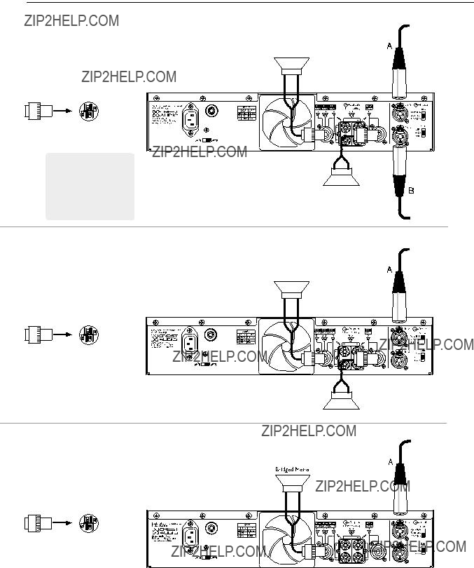
input connection
XLR connector polarity
TRS connector polarity
bridged mono mode parallel mode stereo mode
chassis ground
output connection
speakon output
channel A stereo/parallel channel B stereo/parallel bridged mono
bridged mono
channel B stereo/parallel
p. 12

features overview 3
rear panel
4 Output connections
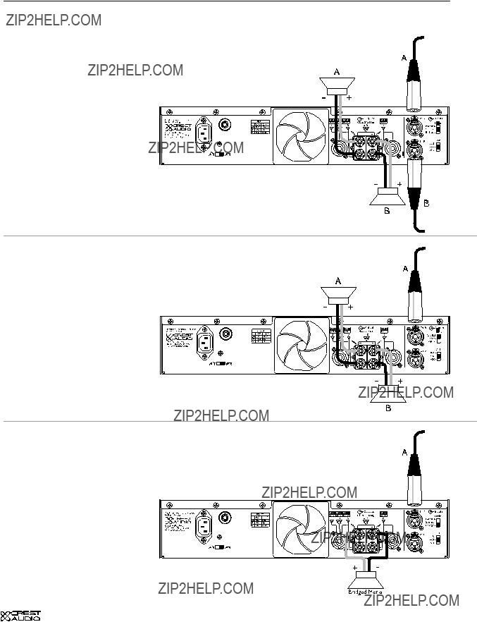
Speakers can be connected via the high current binding posts and the
Binding posts: One pair (Red- hot, Black- ground) per channel.
Speakons - One connector for each channel.The Speakon connector for Channel A also contains contacts for Channel B out put as well (see Operation Modes).
5 Ground lift switch
The recessed
6 Input connections
Input signals can be connected to the amp via the Combi connec- tors, the 1/4??? TRS connectors, and the Female XLR (pin 2 hot) con- nectors. See Connections
In situations where an UNBAL- ANCED signal is fed to the amp, it???s important to ground the unused input. If the inverting
7 Mode selector switch
This recessed, three position switch configures the amplifier for Stereo, Parallel or Bridged Mono operation. The default factory setting is Stereo. See - operation modes.
a
Do not adjust the mode selection switch while the amplifier is
8 Input sensitivity switch
This three position switch allows the user to select the input sensitivity to .775v (0 dBu), X20, or X40 for full rated output power.The default factory setting is X20.
p. 13


operation modes 4
bridged
p. 15

4operation modes
mode selection
The
stereo
In Stereo mode,both channels operate independently,with their input atten- uators controlling their respective levels.Signal at ChannelA???s input produces output at Channel A???s output,while signal at Channel B???s input produces out- put at Channel B???s output.Recommended minimum nominal load impedance for stereo operation is 2 Ohms per channel.
parallel
When set to Parallel mode, program material applied to Channel A???s input will appear at both Channel A and B outputs.The attenuators for Channel A and B controls the level for channel A and B outputs independently of each other.
bridged
Bridged mode straps both amplifier channels together to make a single- channel monaural amplifier. One channel pushes and the other pulls equally, increasing the power output over that of either channel alone
(see Specifications). Signal is applied to the Channel A input only. Channel A???s attenuator is used to control signal level.
Use extreme caution when operating the amplifier in Bridged mode. Never ground either side of the speaker cable when the amplifier is in Bridged mode; both sides are ???hot.???
If an output patch panel is used, all connections must be isolated from each other and from the panel.The recommended minimum nominal load imped- ance in the Bridged mode is 4 ohms, which is the equivalent to driving both channels separately at 2 ohms.
CD owner???s manual
in bridged mode may damage both the amplifier and test equipment!
p. 16
connections 5
/ proper wiring schemes for connectors: speakon binding post
/ correct signal paths: stereo, parallel and bridged
input
XLR 1/4??? TRS
Combi
output
Binding Posts
Speakons
p. 17

5connections
inputs
CD owner???s manual
CD amplifiers are configured standard with pin 2 hot on XLR inputs.
female XLR
TRS pinouts
outputs
Speakers are connected using the
A channel also has
B channel + to PIN 2+
B channel - to PIN 2 -
Note: This is useful in
Please connect your output cable to the + and
- terminals of each sec- tion precisely as shown.
p. 18
connections 5
stereo mode
2 1
3
2 1
3
parallel mode
2 1
3
2 1
3
bridged mono mode
2 1
3
2 1
3
p. 19
5connections
stereo mode
speakon output connectors
Speaker + to PIN 1 +
Speaker - to PIN 1 -
This is handy in situations where the output is dri- ving
CD owner???s manual
A
2 1
3
2 1
3
B
parallel mode
speakon output connectors
A
-
2+
+
+
-
B
bridged mono mode
speakon output connectors
-
Speaker + to PIN 1 +
Speaker - to PIN 2 +
+
2 1
3
2 1
3
p. 20

safety 6
TourClass
p. 21

6safety
CD owner???s manual
user responsibility
Your CD Series amplifier is very powerful and can be potentially dangerous to loud- speakers and operators alike. It is your responsibility to read important precautions (see the
Many loudspeakers can be easily damaged or destroyed by overpowering, especially with the high power available from a bridged amplifier. Always be aware of the speak- er???s continuous and peak power capabilities. Crest Audio is not responsible for damage to loudspeakers for any reason.
speaker protection
All loudspeakers have electrical, thermal and physical limits which must be observed to pre- vent damage or failure.Cone or compression drivers can be damaged (sometimes to the point of failure) from excessive power, low frequencies applied to high frequency drivers, severely clipped wave forms, and DC voltage. All CD Series amplifiers automatically protect speakers from DC voltages and subsonic signals.
Mid- and
The amplifier???s clipping point is its maximum peak output power. At maximum peak output power, Crest Audio CD Series amplifiers will deliver more power than many speakers can safely handle. Be sure the peak power capability of the amplifier is not excessive for your speaker system.To ensure that the speakers never receive excessive power, and to prevent amplifier clipping,use a properly adjusted external limiter (or a compressor with a ratio of 10:1 or higher) to control power output. Use one compressor/limiter for each frequency band in systems with active electronic crossovers.
The ACL clip limiting circuit will automatically limit the duration of
recommended speaker cabling
The wire gauge charts will assist you in determining the optimum copper wire gauge for your speaker cables.Remember that the speaker cable resistance robs amplifier power in two ways: through power lost directly to resistance (often referred to as I2R loss),and through increased total load resistance, which decreases the amount of power available from the amplifier. Appendix C gives cable length figures in feet/AWG wire gauges and in metric values.
p. 22

safety 6
TourClass?? protection
Just like Crest Audio???s highly acclaimed Pro series amps, CD series amps incorporate TourClass protection features. Derived from Crest Audio???s extensive experience with the world???s largest sound rental companies, the TourClass group of circuits sets the industry standard for assured protection of internal amplifier circuits and all connected loads.
ACL ACTIVE CLIP LIMITING
At the amplifier???s full power limit, or clipping point, ACL will be activated.This is indicated by illumination of the ACL / IGM LED.The channel gain is automatically reduced, protecting the loudspeakers from potential damage from the high power,continuous square waves that would otherwise be produced. ACL may be activated by uncontrolled feedback, oscillations, improper equipment gain settings, or an equipment malfunction upstream from the amplifi- er. Only steady or excessive clipping (not normal program transients) will trigger ACL. The circuit is virtually transparent in operation and full signal bandwidth is maintained.
IGM INSTANTANEOUS GAIN MODULATION
IGM is an innovative circuit that allows the amplifier to operate safely into loads as low as 4 ohms.When the amplifier sees a load that overstresses the output stage,the IGM circuit adjusts the channel gain to a safe level. This gain control circuit is inaudible in normal use. In addition, if extreme and sustained low impedance is encountered, the amplifier???s output relay will open.
AutoRamp
Auto Ramp operates every time the amplifier is turned on or is reactivated after a protect condition is corrected.This exclusive CrestAudio feature gradually increases gain to the atten- uator setting avoiding unnecessary stress on the loudspeakers.
Thermal Protect
Abnormally high heat sink temperatures will engage the Protect circuit and disconnects the output relays. During this time the Prot LEDs will light red.The cooling fan will continue run- ning at high speed. Normal operation resumes once the amplifier cools to a safe level.
Short Circuit
If an output is shorted (i.e. defective speakers or crossed speaker wires) the output relays will open and the channel will shutdown.After approximately 2 seconds the channel will attempt an AutoRamp
DC Voltage
If an amplifier channel detects DC voltage at its output terminals,the output relay will immediately open to prevent loudspeaker damage. The protect LEDs illuminate.
Subsonic Frequencies
p. 23


service and support 7
/ ways to contact Crest Audio
contact us
p. 25

7service and support
support
In the unlikely event that your amplifier develops a problem, it must be returned to an authorized distributor, service center, or shipped directly to our factory.
To obtain service, contact your nearest Crest Audio Service Center, Distributor, Dealer, or any of the worldwide Crest Audio offices. For those with Internet access, please visit the Crest Audio web site.
contact us
customer service
phone 201.909.8700 USA fax 201.909.8744 USA
email customerserve@crestaudio.com
technical support
phone 201.909.8700 USA fax 201.587.0550 USA
email techserve@crestaudio.com
web site
www.crestaudio.com
Crest Audio Inc.
Fair Lawn, NJ 07410 USA
CD owner???s manual
Audio???s Customer Service
p. 26
specifications a
CD Series
p. 27

b block diagram
CD owner???s manual
p. 28
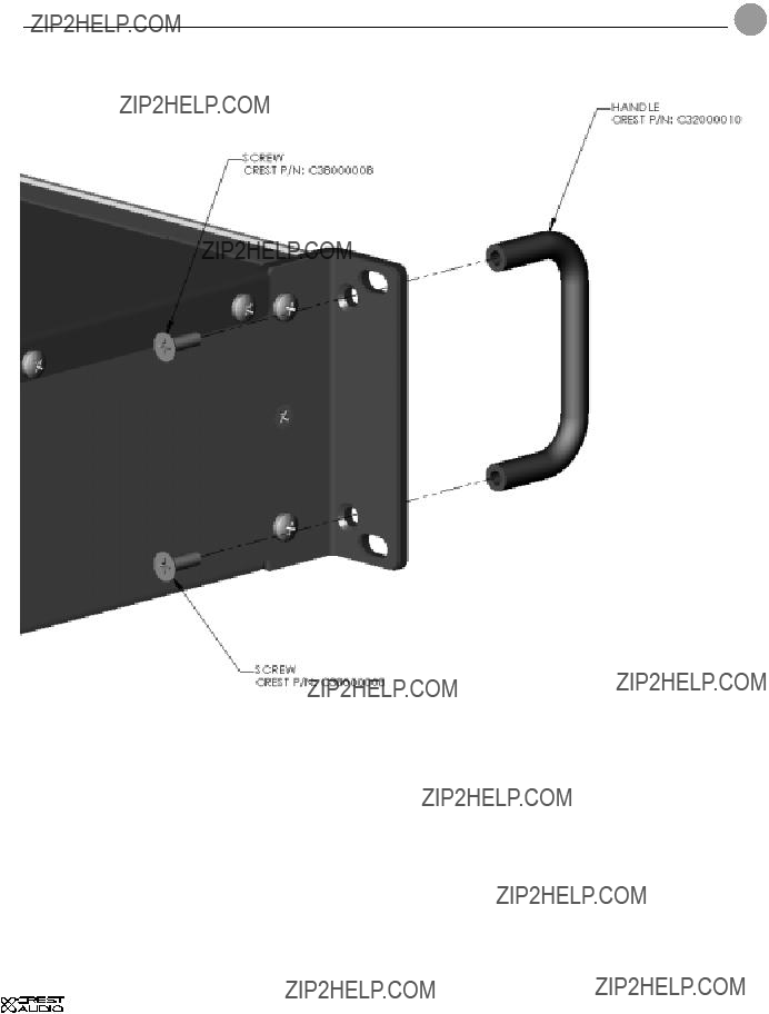
optional handle installation c
The CD amplifiers can be outfitted with optional handles.This option requires (2) CD series handles (P/N C32000010) and (4)
p. 29

d wire gauge
CD owner???s manual
stranded cable length
2meters
5meters
10meters
30meters
p. 30

wire gauge d
stranded cable length
5feet
10feet
40feet
80feet
p. 31

http://www.crestaudio.com CD Owner's Manual Version 1.1 10/14/04
P/N 80305114