PA G E M AT R I X ???
Co n t ro l l e r
ARCHITECTURAL ACOUSTICS
O W N E R ??? S M A N U A L
PA G E M AT R I X ???
Co n t ro l l e r
ARCHITECTURAL ACOUSTICS
O W N E R ??? S M A N U A L

Intended to alert the user to the presence of uninsulated ???dangerous voltage??? within the product???s enclosure that may be of sufficient magnitude to constitute a risk of electric shock to persons.
Intended to alert the user of the presence of important operating and maintenance (servicing) instructions in the literature accompanying the product.
CAUTION: Risk of electrical shock ??? DO NOT OPEN!
CAUTION: To reduce the risk of electric shock, do not remove cover. No user serviceable parts inside. Refer servicing to qualified service personnel.
WARNING: To prevent electrical shock or fire hazard, do not expose this appliance to rain or moisture. Before using this appliance, read the operating guide for further warnings.
Este s??mbolo tiene el prop??sito, de alertar al usuario de la presencia de ???(voltaje) peligroso??? que no tiene aislamiento dentro de la caja del producto que puede tener una magnitud suficiente como para constituir riesgo de corrientazo.
Este s??mbolo tiene el prop??sito de alertar al usario de la presencia de instruccones importantes sobre la operaci??n y mantenimiento en la literatura que viene con el producto.
PRECAUCION: Riesgo de corrientazo ??? ??No abra!
PRECAUCION: Para disminu??r el riesgo de corrientazo, no abra la cubierta. No hay piezas adentro que el usario pueda reparar. Deje todo mantenimiento a los t??cnicos calificados.
ADVERTENCIA: Para evitar corrientazos o peligro de incendio, no deje expuesto a la lluvia o humedad este aparato Antes de usar este aparato, Iea m??s advertencias en la gu??a de operaci??n.
Ce symbole est utilis?? pour indiquer ?? l???utilisateur la pr??sence ?? l???int??rieur de ce produit de tension non- isol??e dangereuse pouvant ??tre d???intensit?? suffisante pour constituer un risque de choc ??lectrique.
Ce symbole est utilis?? pour indiquer ?? l???utilisateur qu???il ou qu???elle trouvera d???importantes instructions sur l???utilisation et l???entretien (service) de l???appareil dans la litt??rature accompagnant le produit.
ATTENTION: Risques de choc ??lectrique ??? NE PAS OUVRIR!
ATTENTION: Afin de r??duire le risque de choc ??lectrique, ne pas enlever le couvercle. Il ne se trouve ?? l???int??rieur aucune pi??ce pouvant ??tre repar??e par l???utilisateur. Confier I???entretien ?? un personnel qualifi??.
AVERTISSEMENT: Afin de pr??venir les risques de d??charge ??lectrique ou de feu, n???exposez pas cet appareil ?? la pluie ou ?? l???humidit??. Avant d???utiliser cet appareil, lisez les avertissements suppl??mentaires situ??s dans le guide.
Dieses Symbol soll den Anwender vor unisolierten gef??hrlichen Spannungen innerhalb des Geh??uses warnen, die von Ausreichender St??rke sind, um einen elektrischen Schlag verursachen zu k??nnen.
Dieses Symbol soll den Benutzer auf wichtige Instruktionen in der Bedienungsanleitung aufmerksam machen, die Handhabung und Wartung des Produkts betreffen.
VORSICHT: Risiko ??? Elektrischer Schlag! Nicht ??ffnen!
VORSICHT: Um das Risiko eines elektrischen Schlages zu vermeiden, nicht die Abdeckung enfernen. Es befind- en sich keine Teile darin, die vom Anwender repariert werden k??nnten. Reparaturen nur von qualifiziertem Fachpersonal durchf??hren lassen.
ACHTUNG: Um einen elektrischen Schlag oder Feuergefahr zu vermeiden, sollte dieses Ger??t nicht dem Regen oder Feuchtigkeit ausgesetzt werden. Vor Inbetriebnahme unbedingt die Bedienungsanleitung lesen.
2
3
4

ENGLISH
1 . I n t r o d u c t i o n
Congratulations on wisely choosing the PageMatrix??? system for your current and future paging projects. Used in conjunction with our
MediaMatrix serves as the central processing unit for an entire project, controlling the entire system from signal routing to managing the paging system. The PageMatrix system provides multiple paging stations that are easily configured to just about any page/zone requirement. Plus, these paging stations are portable, meaning that the wall plug/port contains the identity of the paging station connected to it.
The PageMatrix hardware components include the
The software components include:
???PageMatrix Software
???MediaMatrix view files
???MediaMatrix PASHA??? paging files (corresponds to the appropriate view file)
The PageMatrix application provides a graphical way to program the zone preset buttons of each attached station. Once the configuration is finalized, it is simply downloaded to the PageMatrix Controller for operation. It is not necessary to access the PageMatrix application again until the time comes to update the configuration.
Features
???99 available page zones
???16 simultaneous pages
???Any combination of four or ten button stations can be used.
???All stations feature
???Controller features a station power input for remote +24V DC operation.
???Phoenix connectors are used to connect paging audio to MediaMatrix BoBs.
???Controller supports up to four MediaMatrix systems.
???Controller offers 16 front panel station LEDs which indicate station status.
5
2 . H a r d w a r e D e s c r i p t i o n
2 . 1 P a g e m a t r i x C o n t r o l l e r
The PageMatrix controller is the heart of the system. It is connected via an
The PageMatrix controller supports up to 16 unique paging stations including any combination of the Station
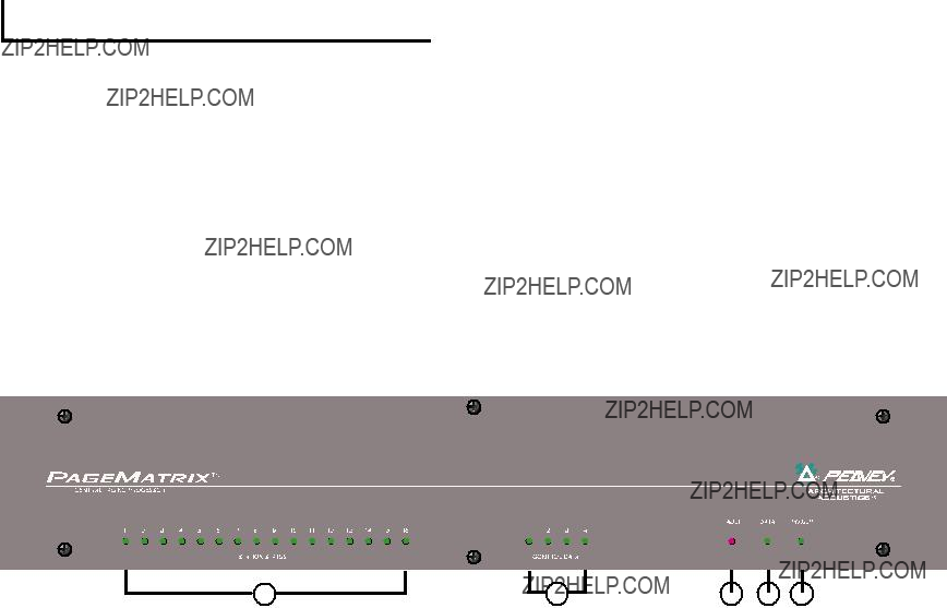
Front Panel
1.Station Status LEDs: (16) Displays green after software activation.
2.Control LEDs: (4) Lights up green when the control data ports are in use.
3.Fault LED: Download error indication when downloading the PageMatrix configuration to the PageMatrix controller. When this message occurs, download the configuration again.
4.Data LED: Indicates a data transfer to the unit or that valid data exists in memory at power up.
5.Power : Indicates that the unit is on.
6
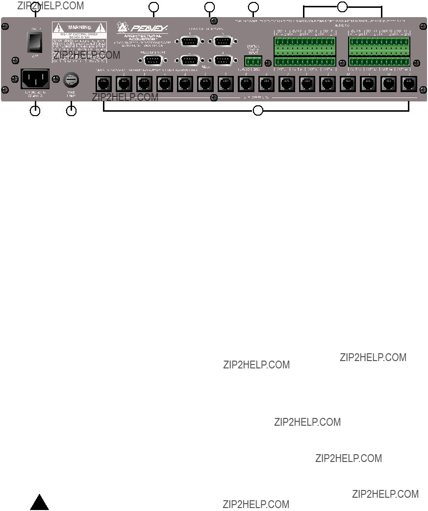
Rear Panel
6.Program Port
7.Control Data Ports (4
8.Station Inputs (16 RJ45 jacks): All stations are connected to one of the sixteen station inputs using standard CAT 5 cable. The cable carries audio from the station and control data to and from the station, as well as power for the station. Note: This is not a network connection.
9.Audio Outputs: Four removable ???Phoenix??? style connectors are provided for connection of
audio to MediaMatrix Break out Box. Note: Two BoBs (8 channels each) are required for 16 stations.
10.Station Power Input: +24V DC input for emergency station power.
Note: In the event of a power loss to the paging controller, the station power input will power only the stations to allow audio to pass in an emergency situation. In this case, the stations will be unable to communicate with the controller, and the controller will be unable to send control information to the MediaMatrix unit. In the event of a power loss, the MediaMatrix view file must be configured to route the audio without control input from the PageMatrix controller. In order for both the controller and stations to remain active, the controller must be connected to some form of power backup system, such as a UPS.
11.Power Switch: Use to turn the unit on or off.
12.Detachable Power Cord Connector
13.Fuse: 1A at 100V/120V AC~, T1A/250V
500 mA at 230V AC~, T500mA/250V
7

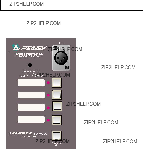
2 . 2 . S t a t i o n F o u r - W ??? W a l l - M o u n t P a g i n g S t a t i o n
Station
Front Panel
Zone Preset buttons w/LEDs(4):
Used to select any of the four zone presets. A green LED indicates the zone is available, while a red LED indicates it is in use by another station. The LED will blink to confirm the selection.
Used to connect the supplied
Mic Volume:
Recessed to the right of the microphone input, use a small screwdriver to adjust the mic gain.
Rear Panel
This is the analog audio signal output to be connected to the PageMatrix controller.
See the wiring diagram, Appendix 5.3.
This connects the control data to and from the PageMatrix controller and also the power for the station. See the wiring diagram, Appendix 5.3.
8
S t a t i o n F o u r - W O p e r a t i o n
???LED color indicates status of each of the four Zone presets.
???Green indicates the zone is available and not in use by another station.
???Red indicates the zone is in use.
???When the microphone ???Talk??? button is pressed, the selected zone preset LED turns orange to confirm that it is active. Other stations connected to the system will indicate RED to confirm that this particular zone is in use.
???Press any Zone Preset button to select. The LED will blink confirming the selection.
???At
???
???Zone presets can be labeled in the appropriate white boxes.
???If all LEDs flash red at power up, this indicates the station has not been programmed.
???If all LEDs flash green at power up, this indicates the station has been programmed.
A b o u t Z o n e P r e s e t s
MediaMatrix defines the zones which can represent single outputs or groups of outputs. PageMatrix software is used to program the button assignments on the paging stations which enables them to access one or more zones per button. We refer to the button assignments as zone presets, since these settings are set initially. They are then downloaded to the PageMatrix controller where they become active.
A b o u t P r i o r i t y
With PageMatrix, there are no inherent priority settings. Any microphone may be used at any time and the ???busy??? LED indication identifies when a zone preset is in use by another station. However, extensive priority levels can be configured and designed within MediaMatrix.
9

2 . 3 . S t a t i o n F o u r ??? D e s k t o p P a g i n g S t a t i o n
Station Four??? is a four button desktop station that includes an electret condenser microphone. Each of the four button zone presets are defined and programmed by the PageMatrix software.
Front Panel
Push To Talk button:
Press and hold to enable the microphone for the selected zone preset. The selected LED will turn orange to denote active status while the other zone preset LEDs become red.
Zone Preset buttons w/ LED(4):
Used to select any one of the four zone presets. A green LED indicates the zone is available, while a red LED indicates it is in use by another station. The LED will blink to confirm selection.
XLR Mic Input:
Phantom powered microphone input
Mic Volume:
Recessed mic gain adjustment
Rear Panel
For connection of a remote microphone with a
S t a t i o n F o u r O p e r a t i o n
???LED color indicates status of each of the four Zone presets.
???Green indicates the zone is available and not in use by another station.
???Red indicates the zone is in use.
???When the Push To Talk button is pressed, the selected zone preset LED turns orange to confirm that it is active. Other stations connected to the system will indicate RED to confirm that this particular zone preset is in use.
???Press any zone preset button to select. The LED will blink confirming the selection.
???At
???Zone presets can be labeled in the appropriate white boxes.
???If all LEDs flash red at power up, this indicates the station has not been programmed.
???If all LEDs flash green at power up, this indicates the station has been programmed.
???The Aux mic input (rear panel) is always routed to zone preset one.
10
2 . 4 . S t a t i o n T e n ??? D e s k t o p P a g i n g S t a t i o n
Station Ten??? is a ten button desktop station that includes an electret condenser microphone. Each of the ten zone presets are defined and programmed by the PageMatrix software. In addition, a 12 button ???telephone style??? key pad and 20 x 2 LCD panel are provided for selection and indication of up to 99 ???virtual??? zones. The ten buttons are unique for each station; however, the additional 89 ???virtual???
Front Panel
Push To Talk button:
Press to activate the microphone for the selected zone preset.
Zone Preset buttons w/ LED(10):
Used to select any of the ten zone presets. A green LED indicates the zone is available, while a red LED indicates it is in use. The LED will blink to confirm selection.
XLR Mic Input:
Phantom powered microphone input.
Mic Volume:
Recessed mic gain control.
Rear Panel
Aux Mic Input
For connection of a remote microphone with a
RJ45 Connector:
For connection to the PageMatrix controller.
11
S t a t i o n T e n O p e r a t i o n
???LED color indicates status of each of the ten zone presets.
???Green indicates the zone is available and not in use by another station.
???Red indicates the zone is in use.
???When the Push To Talk button is pressed, the selected zone preset LED turns orange to confirm that it is active. Other stations connected to the system will indicate RED to confirm that the zone preset is in use.
???Press any Zone Preset button to select. The LED will blink confirming the selection.
???At
???Aux Mic input
???For direct zone preset access, the key pad can be used. Simply enter a one or two digit number, then press # to select.
???The selected zone name (user nameable up to 16 characters within the PageMatrix software) will be displayed on the 20 x 2 LCD in addition to status (ready/busy/paging)
???The upper line of the display provides the station name and status. The second line provides the zone name.
???Zone presets can be labeled in the appropriate white boxes.
???If all LEDs flash red at power up, this indicates the station has not been programmed.
???If all LEDs flash green at power up, this indicates the station has been programmed.
???At
A b o u t Z o n e P r e s e t s
MediaMatrix defines the zones which can represent single outputs or groups of outputs. PageMatrix software is used to program the button assignments on the paging stations which enables them to access one or more zones per button. We refer to the button assignments as zone presets, because these settings are set initially then downloaded to the PageMatrix controller where they become active.
A b o u t P r i o r i t y
With PageMatrix, there are no inherent priority settings. Any microphone may be used at any time and the ???busy??? LED indication identifies when a zone preset is in use by another station. However, extensive priority levels can be configured and designed within MediaMatrix.
12

2 . 4 . T y p i c a l P a g e M a t r i x C o n n e c t i o n
Up to 16 Stations of any combination
CAT 5 STANDARD ???Data Type??? cable is used.
However, there is voltage on the line. DO NOT
CONNECT to computer networks.
Station 4W???
CAT 5*
Cable
MediaMatrix??
Cable
BoB Cable
IA??? 200
CAT 5*
Cable
PageMatrix???
Audio
Cable
Lap Top
OR
MediaMatrix??
Com Port
13

3 . P a g e M a t r i x S o f t w a r e D e s c r i p t i o n
3 . 1 . C o m p u t e r R e q u i r e m e n t s
Minimum:
3 . 2 . S o f t w a r e I n s t a l l a t i o n
Note: With MediaMatrix Mainframe systems shipped since 1999, the PageMatrix application is already installed. The instruc- tions below only apply to systems prior to this time.
The complete PageMatrix software system includes:
1.PageMatrix application (Floppy Disk 1)
2.MediaMatrix view files and PASHA??? files (Floppy Disk 2)
3.MediaMatrix devices (Floppy Disk 2)
Step One: Installing the PageMatrix software (files in parentheses indicate defaults)
A.Insert Disk One (PageMatrix Installation) into the floppy drive.
B.Run ???A:\setup.exe???.
C.Will prompt for an installation directory (c:\pagemtrx) and a program group name (PageMatrix). Installs files in that directory and creates program group. When installation window says ???Installation Complete!??? in red, click the Finish button or cancel button (if there is no finish button). You do not need to restart your computer after installation.
Step Two: Installing the MediaMatrix view files:
Note: When installing the PageMatrix view files and devices, you will need to know what directory your MediaMatrix software is in (if it is in a different directory than the factory defaults).
A.Insert Disk Two (MediaMatrix view Files) into the floppy drive.
B.Run ???A:\views.exe???.
C.This is a
D.Once the directory is confirmed, click Unzip.
E.Click Close when finished.
Step Three: Installing the MediaMatrix devices
A.Insert Disk Two (MediaMatrix view Files) into the floppy drive.
B.Run ???A:\devices.exe???.
C.This is a
D.Once the directory is confirmed, click Unzip.
E.Click Close when finished.
14

3 . 2 . 1 . L a u n c h i n g P a g e M a t r i x
Windows 95:
1.Under the Start menu, select Programs.
2.Find the PageMatrix directory and select it.
3.Locate PageMatrix , and select it.
Windows 3.1:
1.Find the PageMatrix Program Group within the Program Manager
2.Doulbe click the group, then double click the PageMatrix Icon.
Note: For systems that are not
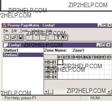
3 . 2 . 2 . S t a t i o n s a n d Z o n e s
The PageMatrix application simplifies the process of programming the remote stations. A grid matrix is presented that lists each button for the selected station. HB stands for hardware button and the following number signifies the specific button on the station. Station buttons are displayed in rows and potential zone assignments in columns.
To assign the button, simply
Zones represent physical locations and outputs
connected via MediaMatrix BoB outputs, amplifiers, and speakers. Note: If you only use one BoB, a maximum of 8 zones will be available.
Programming the Paging Stations with the PageMatrix application
[note: see the next chapter (Menu Bar) for additional information]
Use the ???Insert Station??? or ???Add Station??? (Edit Menu) as necessary to include your hardware stations in the programming. After setting up the PageMatrix application, the layout on the left displays a column listing all the connected paging stations. To the right is a matrix list of zones at the top and columns of buttons by number. Select the station you wish to program first, then use the mouse to activate zones for each button. When finished, download the configuration to the Pagematrix controller (File menu). Now your page station buttons are programmed and ready for use.
Naming Zone Presets When Using the Station Ten
With the Station Ten, a 20 x 2 display is provided for viewing the zone presets. The zone presets are named within the PageMatrix application. When a 10 button station is inserted (Edit/Insert Station), the LCD Text option appears at the top of the screen. Simply select a virtual button, then highlight the default title and rename as you wish up to 16 characters.
15

3 . 3 . P A G E M A T R I X A P P L I C A T I O N M E N U B A R O V E R V I E W
3.3.1 File Menu
New
Selecting New opens a new configuration set to factory defaults.
Open
Brings up the standard file open dialog that allows you to open an existing file (*.pmx).
Close
Closes the active configuration.
Save
Save the current configuration and any edits you have made.
Save As
Brings up the standard file save dialog and allows you to rename the file before you save it.
Not active at this time.
Print Preview
Not active at this time.
Print Setup???
Not active at this time.
Download Configuration???
This option allows you to send your configuration settings to the PageMatrix controller. Since this will replace the current configuration loaded into the controller, a ???Do you wish to continue???? dialog gives you the opportunity to cancel.
Recent File List
This area of the menu lists the most recent configurations. These configurations may be opened directly from the list.
Exit
Closes PageMatrix.
16

3.3.2. Edit Menu
Undo
Not active at this time
Cut
Not active at this time
Copy
Not active at this time
Paste
Not active at this time
Insert Station
Creates a new paging station that is available for editing. It is placed in the list before the currently selected station. Selecting this option opens the ???New Station Properties??? dialog and allows the following edits:
Station Name: Up to 16 characters.
Number of buttons: 4 or 10.
PAC Port: Identifies the specific port
PAC Port Address: Currently, always set to one.
Add Station
Creates a new paging station that is available for editing. It is placed at the end of the list. Selecting this option opens the ???New Station Properties??? dialog and allows the following edits:
Station Name: Up to 16 characters.
Number of buttons: 4 or 10.
PAC Port: Identifies the specific port
PAC Port Address: Currently, always set to one.
Delete Station
Removes the currently selected station. The ???Are You Sure??? dialog opens for confirmation.
17

3.3.3. Tools Menu/Options
View Toolbar
Show or hide the screen toolbar.
View Status Bar
Show or hide the status bar at the bottom of the window.
View Station Addresses
Displays the station address in front of the station name.
Max Number of Zones
Use this parameter to set the maximum number of zones used in your system.
Communications
Used to set the upload/download port. In addition to COM
3.3.4. Window Menu
New Window
Creates a new window.
Cascade
Standard Windows function that arranges all open configuration windows in a cascade pattern.
Tile
Standard Windows function that arranges all open configuration windows in a tile pattern.
Arrange Icons
Aligns minimized child windows.
Configuration Display
Lists all open configurations.
3.3.5.Help Menu
About PageMatrix
Displays the PageMatrix
18

4 . 0 . T y p i c a l P a g e M a t r i x O p e r a t i o n
4 . 1 . O v e r v i e w
4.1.1. The components
PageMatrix / MediaMatrix paging systems consist of five primary components:
???At least one PageMatrix paging station connected to the PageMatrix controller via the proper category five cabling
???PageMatrix controller with the appropriate configuration file loaded
???PageMatrix application software
???A MediaMatrix audio system with PASHA running
???A proper PASHA.ini file configured for the ???View File??? compiled
4.1.2.Connections
Paging stations connect to the PageMatrix controller via CAT 5 cabling. This cable
carries three ???signals?????? the analog audio from the microphone, the voltage required to power the remote paging station, and the serial control data which will determine where the microphone???s audio signal will be routed by MediaMatrix.
The analog microphone signals from all paging stations are individually connected from their outputs on the rear of the PageMatrix Controller to the signal inputs of MediaMatrix break out boxes (???BoBs???).
One of the serial outputs on the rear of the PageMatrix Controller connects to one of the Com Ports on the rear of the MediaMatrix frame.
4.1.3. The Desktop Paging Stations (Station Four and Station Ten)
There is no local switching of the
4.1.4. The PageMatrix Controller
There are three functions of this device:
1:To provide power to the Paging stations.
2:To pass the analog microphone signals from the paging stations to the inputs of the MediaMatrix system???s BoBs.
19
3:To interpret the proprietary control data from the paging stations and convert it to standard serial strings which can be forwarded to MediaMatrix.
Microphone signals from the paging stations are not acted upon by the PageMatrix Controller, but are simply passed through the box as received. Any switching or routing is done within MediaMatrix.
4.1.4. The MediaMatrix system and PASHA
Among many other tasks, the MediaMatrix system receives the analog audio from the Paging Stations via the PageMatrix controller, converts it to digital and performs all processing of those signals, including the routing of these signals to the various ???zones???. These routing functions are accomplished by special PageMatrix devices within the system???s ???View File??? which are controlled from the PageMatrix Controller via PASHA.
4.1.5.
1:Pressing a station???s zone preset button selects the configured zones in MediaMatrix.
2:When the
3:This serial command is interpreted by MediaMatrix (via PASHA) and ???presses??? the appropriate router buttons in the MediaMatrix view file to send the audio to the zone or combination of zones selected by the paging station.
4:Audio passes to the zone(s) through MediaMatrix as long as the
5:Functions such as paging priorities, signal source ducking, zone equalization, etc. are all functions of the MediaMatrix system and are not directly acted upon by the PageMatrix components.
4.1.6.Operation within MediaMatrix
Paging devices can be complicated systems consisting of multiple ???mixing routers.??? For example, programming a paging device which consists of 8 stations and 32 buttons requires that a PASHA file be written addressing each of the matrix locations (256 parameters). Since programming your own Pasha files would require extensive time, we have provided a variety of view files and associated PASHA.INI files to simplify the task. We highly recommend you use the files we???ve provided on floppy disk and edit them for your specific application.
20
Basic
1.Find the appropriate .txt file for the device you wish to use.
2.Rename this file to pasha.ini and place in the Peavey directory (mediamatrix\views).
Note: If you wish to keep the original pasha.ini file, just rename it.
3.Open MediaMatrix (if not already launched).
4.From the Device menu select ???Paging??? to view the available devices.
5.Select an existing device and wire it accordingly.
6.Test the routings and zones.
Example:
Suppose we want to use the 1632.pav file. Rename the 1632.txt file to pasha.ini. Move this newly created pasha.ini to the MediaMatrix root directory.
4.2. Troubleshooting 101
???Remember, the view file must be compiled.
???Make sure Pasha.com(pasha.com1, pasha.com2, pasha.com3, or pasha.com4) is launched and matches the same com port used for PageMatrix.
???Be sure to launch PageMatrix and program a test file.
???In MediaMatrix, check the view file visual monitors to determine if the system is responding.
???Finally, check cable type, connection, and port settings.
21

5 . A P P E N D I X
5 . 1 . F a c t o r y S u p p o r t
Peavey provides customer support and service direct from the factory. If you need further assistance or information, don???t hesitate to call us. You can reach us 8 a.m. - 5 p.m. CST at (800)
Peavey Electronics Corp. ??? MediaMatrix Support Group ??? 711 A St. ??? Meridian, MS 39301
You can also access helpful tips, specifications, FAQs, sample files, application notes and other Peavey Architectural Acoustics equipment product information 24 hours a day, seven days a week at our site on the World Wide Web. The URL is:
http://www.peavey.com/division/arch/index.html
In order to provide you with the best technical support, it will probably be necessary to see your view file so we can accurately diagnose your problem. This also helps to streamline your work and make your system more efficient. Using the Internet and
Please direct your mail and attached view file to:
George Douglas, National Sales Manager george@peavey.com
Ken Valentine, Central District Manager ken@peavey.com
Will Roland, Western District Manager will@peavey.com
Joel Moak, Southeastern District Manager joel@peavey.com
Levin Culpepper, Internal Tech Support Coordinator levin@peavey.com
Brent Harshbarger, Product Manager brent@peavey.com
If you need emergency assistance after business hours or on the weekend, you may reach one of us on our SkyPager at (800)
A R C H I T E C T U R A L A C O U S T I C S?? 711 A Street ??? Meridian, MS 39301
(601)
Features and specifications are subject to change without notice.
22

5 . 2 . U s i n g t h e M e d i a M a t r i x P r o g r a m L a u n c h e r
The Program Launcher is found in the Device/Miscellaneous Menu. It is used to make it easy to open another Windows application while you are using MediaMatrix. You can label the Program Launcher block and include it in any window of a MediaMatrix design. The Program Launcher device can either launch another Windows??? application or switch to that application if it is already running. The Object Properties dialog for this object has a field titled ???Run this program??? that contains the complete path and file name and optional command line arguments of the program you want to run. You can browse the applications that are currently running by pressing the ???Window Title...??? button, and you can browse for executables (*.exe) by pressing the ???File Name...??? button. The object can perform its action, either running or switching to the other application, on either a single mouse click or on a
23

5 . 3 . S t a t i o n 4 - W W i r i n g D i a g r a m
1
 485+
485+
2 
 485 -
485 -
3 
 GND
GND
4 
 24V+
24V+
5 
 GND
GND
CAT 5
54
NOTE:
This is not a network connection.
24

5.4.
 Audio +
 Audio -
 Mic Switch
 GND
GND
25

5 . 5 . C o n f i g u r i n g t h e P a g e M a t r i x C o n t r o l l e r
As mentioned previously, the PageMatrix controller supports up to sixteen paging stations simultaneously. In larger applications where multiple controllers are necessary, the various PageMatrix units must be configured for IDs beyond the default
1.Remove top plate of the controller (six screws).
2.Now viewing the inside of the unit, find the DIP switch (labeled SW100) located at the front left side of the unit.
3.You will only adjust switches 1 and 2 according to the chart below.
4.Switches 3 through 8 are inactive.
DIP SETTINGSCONTROLLER IDs
1 2 3 4 5 6 7 8
O
N
Stations 33 - 48
NOTE: Factory settings default to
26

5 . 6 . S p e c i f i c a t i o n s
P a g e M a t r i x
P o w e r R e q u i r e m e n t s :
D o m e s t i c : 1 2 0 V A C ~ , 6 0 H z , 5 0 W
E x p o r t : 1 0 0 V A C ~ , 5 0 / 6 0 H z , 5 0 W 2 3 0 V A C ~ , 5 0 / 6 0 H z , 5 0 W
I n c l u d e d A c c e s s o r i e s :
I E C L i n e C o r d
( 4 ) 1 2 p o s i t i o n P h o e n i x - t y p e c o n n e c t o r s ( 1 ) 3 p o s i t i o n P h o e n i x - t y p e c o n n e c t o r
D i m e n s i o n s a n d W e i g h t :
3 . 5 " H x 1 9 " W x 1 1 . 6 9 " D ( e x c l u d i n g c o n n e c t o r s )
1 3 . 7 l b s .
C o n t r o l l e r
C a t e g o r y 5 c a b l e l e n g t h
M a x i m u m 1 , 0 0 0 f t
N o t e : S t a n d a r d ??? d a t a t y p e ??? c a b l e i s u s e d ; h o w e v e r , t h e r e i s v o l t a g e o n t h e l i n e .
D O N O T c o n n e c t t o c o m p u t e r n e t w o r k s .
Station
Station
It is recommended to use a standard 4 Gang Electrical box with these dimensions: 3.75" H x 7.5" W x 2.0" (Min) D.
P a g i n g S t a t i o n s
M a x i m u m I n p u t L e v e l :
S t a t i o n 4 W a l l m o u n t : - 2 2 d B u
S t a t i o n 4 D e s k t o p : - 2 2 d B u
S t a t i o n 1 0 D e s k t o p : - 2 2 d B u
M a x i m u m O u t p u t L e v e l :
S t a t i o n 4 W a l l m o u n t : + 2 5 d B u
S t a t i o n 4 D e s k t o p : + 2 5 d B u
S t a t i o n 1 0 D e s k t o p : + 2 5 d B u
I n p u t I m p e d a n c e :
S t a t i o n 4 W a l l m o u n t : 2 . 2 K o h m s
S t a t i o n 4 D e s k t o p : 2 . 2 K o h m s
S t a t i o n 1 0 D e s k t o p : 2 . 2 K o h m
O u t p u t I m p e d a n c e :
S t a t i o n 4 W W a l l m o u n t : 2 0 0 o h m s
S t a t i o n 4 D e s k t o p : 2 0 0 o h m s
S t a t i o n 1 0 D e s k t o p : 2 0 0 o h m s
F r e q u e n c y R e s p o n s e :
Station 4 Wallmount: 20Hz to 20 kHz (+0,
S t a t i o n 4 D e s k t o p : 2 0 H z t o 2 0 k H z ( + 0 , - 2 d B )
S t a t i o n 1 0 D e s k t o p : 2 0 H z t o 2 0 k H z ( + 0 , - 2 d B )
T o t a l H a r m o n i c D i s t o r t i o n :
S t a t i o n 4 W a l l m o u n t : L e s s t h a n 0 . 0 1 % a t 1 k H z
S t a t i o n 4 D e s k t o p : L e s s t h a n 0 . 0 1 % a t 1 k H z
S t a t i o n 1 0 D e s k t o p : L e s s t h a n 0 . 0 1 % a t 1 k H z
S i g n a l - t o - N o i s e R a t i o :
S t a t i o n 4 W a l l m o u n t : G r e a t e r t h a n 8 8 d B
S t a t i o n 4 D e s k t o p : G r e a t e r t h a n 8 5 d B
S t a t i o n 1 0 D e s k t o p : G r e a t e r t h a n 8 4 d B
P h a n t o m P o w e r :
S t a t i o n 4 W a l l m o u n t : + 4 8 V D C
S t a t i o n 4 D e s k t o p : + 4 8 V D C
S t a t i o n 1 0 D e s k t o p : + 4 8 V D C
P o w e r R e q u i r e m e n t s :
S t a t i o n 4 W a l l m o u n t : 4 8 m A a t + 2 4 V D C
S t a t i o n 4 D e s k t o p : 5 5 m A a t + 2 4 V D C
S t a t i o n 1 0 D e s k t o p : 9 2 m A a t + 2 4 V D C D i m e n s i o n s :
S t a t i o n 4 W a l l m o u n t : 4 . 5 " H x 8 . 2 " W x 1 " D
S t a t i o n 4 D e s k t o p : 4 . 0 " H x 5 . 2 " W x 7 . 1 " D
S t a t i o n 1 0 D e s k t o p : 4 . 0 " H x 1 0 . 4 " W x 7 . 1 " D
27

ESPA??OL
1. Introducci??n
Lo felicitamos por su sabia elecci??n del sistema PageMatrix??? para sus proyectos de intercomunicaci??n actuales y futuros. Utilizado en conjunto con nuestro aclamado sistema de audio digital MediaMatrix??, el sistema PageMatrix provee un enfoque integrado y flexible para todas las aplicaciones de intercomunicaci??n profesionales.
MediaMatrix sirve como unidad central de procesamiento al proyecto en su totalidad, control??ndolo, desde el encaminamiento de la se??al, hasta la administraci??n integral del sistema de intercomunicaci??n. El sistema PageMatrix provee varias estaciones de intercomunicaci??n, que se configuran f??cilmente para satisfacer cualquier requisito de localizaci??n/zona. Adem??s, estas estaciones de intercomunicaci??n son port??tiles, lo que significa que el enchufe/puerto de pared contiene la identidad de la estaci??n de intercomunicaci??n conectada a ??l.
Los componentes de hardware del sistema PageMatrix, incluyen el controlador PageMatrix, que ocupa dos espacios de bastidor, y tres tipos de estaciones de intercomunicaci??n. El controlador PageMatrix soporta cualquier combinaci??n de hasta 16 estaciones de intercomunicaci??n, para la gesti??n de audio se conecta con las cajas distribuidoras (BoB) del sistema MediaMatrix y para el control de datos se conecta con el puerto serie
Los componentes de software incluyen:
???El software PageMatrix
???Los archivos de visualizaci??n MediaMatrix
???Los archivos de intercomunicaci??n MediaMatrix PASHA??? (que se corresponden con los archivos de visualizaci??n apropiados)
La aplicaci??n PageMatrix provee un medio gr??fico para programar los botones preconfigurados de zona de cada estaci??n agregada. Una vez que finaliza la configuraci??n, la transmite directamente al controlador PageMatrix para su operaci??n. No es necesario acceder nuevamente a la aplicaci??n PageMatrix, hasta que llegue el momento de actualizar la configuraci??n.
Caracter??sticas
???Disponibles 99 zonas de intercomunicaci??n
???Con hasta 16 estaciones de intercomunicaci??n simult??neamente
???Se puede utilizar cualquier combinaci??n de estaciones de cuatro o diez botones
???Todas las estaciones tienen indicadores LED multicolores, que indican el estado de precon figuraci??n de la zona.
28

???El controlador dispone de una entrada para el funcionamiento con alimentaci??n a distancia de +24 VCC.
???Se utilizan conectores tipo Phoenix para llevar la se??al de intercomunicaci??n de audio a las cajas distribuidoras BoB.
???El controlador sustenta hasta cuatro sistemas MediaMatrix.
???En el panel frontal del controlador hay 16 LED de estaci??n, que indican el estado de cada una de ellas.
2.Descripci??n del hardware
2.1 Controlador PageMatrix
El controlador PageMatrix es el coraz??n del sistema. A trav??s del puerto serie
de control, hay un puerto exclusivo, disponible para recibir los datos del software PageMatrix. Normalmente, una vez que se dise??a la configuraci??n PageMatrix, se la transfiere al controlador PageMatrix y el sistema MediaMatrix se desconecta del puerto de programas.
El controlador PageMatrix sustenta hasta 16 estaciones de intercomunicaci??n exclusivas, lo que incluye cualquier combinaci??n de estaciones Station
Consulte los diagramas del panel delantero en la secci??n de ingl??s de est manual pg. 6
Panel Frontal
1.LED indicadores de estado de las estaciones: (16) Muestran el color verde despu??s de la activaci??n del software.
2.LED indicadores de control: (4) Se encienden de color verde cuando est?? en uso el puerto de control de datos.
3.LED indicador de fallas: Indicaci??n de error al cargar la configuraci??n PageMatrix en el controlador PageMatrix. Cuando se produce ese mensaje, vuelva a cargar la configuraci??n.
4.LED indicador de datos: Indica la transferencia de datos a la unidad o la existencia de datos en la memoria al poner en marcha el sistema.
5.LED de encendido: Indica que la unidad est?? activada.
29

Panel posterior
6.Puerto de programas
7.Puertos de datos (4 enchufes
8.Entradas de estaciones (16 enchufes RJ45 hembra): Todas las estaciones est??n conectadas a una de las 16 entradas de estaci??n, mediante un cable CAT 5 est??ndar. El cable transporta se??ales de audio desde la estaci??n y datos de control hacia y desde la estaci??n, as?? como alimentaci??n para la misma. Nota: ??sta no es una conexi??n de red inform??tica.
9.Salidas de audio: Se proveen cuatro conectores desmontables tipo ???Phoenix??? para la
conexi??n del audio a la caja distribuidora BoB del sistema MediaMatrix. Nota: Para 16 estaciones, se requieren dos cajas distribuidoras BoB (de 8 canales cada una).
10.Entrada de alimentaci??n a la estaci??n: Entrada de +24 VCC para alimentaci??n de emergencia de la estaci??n.
Nota: En el caso de que se interrumpa la alimentaci??n el??ctrica al controlador del sistema de intercomunicaci??n, la entrada de alimentaci??n a la estaci??n s??lo alimenta a la misma para permitir el paso de la se??al de audio en una situaci??n de emergencia. En este caso, las estaciones no pueden comunicarse con el controlador y el controlador puede enviar informaci??n de control a la unidad MediaMatrix. En caso de p??rdida de alimentaci??n, el archivo de visualizaci??n del sistema MediaMatrix debe estar configurado para encaminar la se??al de audio sin entrada de se??al de control del controlador PageMatrix. A fin de que tanto el controlador como las estaciones permanezcan activadas, el controlador debe estar conectado a un sistema de respaldo de la alimentaci??n, tal como una unidad de alimentaci??n ininterrumpible (UPS).
11.Interruptor de encendido: Utilizado para activar y desactivar la estaci??n.
12.Conector desmontable del cable de alimentaci??n
13.Fusible: 1 A a 100/120 VCA~, T1A/250V
500 mA a 230 VCA~, T500 mA/250V
30
2.2. Estaci??n de intercomunicaci??n de pared Station
Es una estaci??n de intercomunicaci??n que incluye un micr??fono port??til (de 5 terminales) con un pulsador para hablar. Cada una de las preprogramaciones de las cuatro zonas de intercomunicaci??n se define y programa con el software PageMatrix.
Panel frontal
Botones de zonas preprogramadas con LED indicadores (4):
Utilizados para seleccionar cualquiera de las cuatro zonas preprogramadas. El LED de color verde indica que la zona est?? disponible, mientras que el de color rojo indica que est?? siendo utilizada por otra estaci??n. El LED indicador destella para confirmar la selecci??n.
Entrada de micr??fono de 5 terminales:
Se utiliza para conectar el micr??fono port??til de 5 terminales suministrado.
Volumen de micr??fono:
Embutido a la derecha de la entrada de micr??fono. Utilice un destornillador peque??o para ajustar la ganancia de micr??fono.
Panel posterior
Conector de 3 terminales:
Es la salida de la se??al anal??gica de audio para conectarse al controlador PageMatrix.
Consulte el diagrama de cableado en el Ap??ndice 5.3.
Conector de 4 terminales:
Conecta los datos de control hacia y desde el controlador PageMatrix y tambi??n la alimentaci??n de la estaci??n. Consulte el diagrama de cableado en el Ap??ndice 5.3.
31
Operaci??n de la estaci??n Station
???El color del LED indica el estado de cada una de las zonas preprogramadas.
???El color verde indica que la zona est?? disponible y que no est?? siendo utilizada por otra estaci??n.
???El color rojo indica que la zona est?? en uso.
???Cuando se oprime el bot??n para hablar, el LED indicador de la zona preprogramada se ilumina de color naranja, para confirmar que est?? activada. En las otras estaciones conectadas al sistema, los LED se iluminan de color rojo, para confirmar que esa zona preprogramada est?? en uso.
???Para seleccionar una zona preprogramada, oprima su bot??n. El LED indicador destella para confirmar la selecci??n.
???Al encender el sistema, la estaci??n, por defecto, selecciona la zona 1. Despu??s de un minuto de inactividad vuelve a la zona 1.
???El micr??fono port??til de 5 terminales se activa oprimiendo el bot??n para hablar.
???Las zonas preprogramadas se pueden rotular en las casillas de color blanco correspondientes.
???Si todos los LED indicadores destellan en rojo al encender el sistema, eso indica que la estaci??n no ha sido programada.
???Si todos los LED indicadores destellan en verde al encender el sistema, eso indica que la estaci??n ha sido programada.
Acerca de las zonas preprogramadas
El sistema MediaMatrix define las zonas, que pueden ser salidas independientes o grupos de salidas. El software PageMatrix se utiliza para programar las asignaciones de los botones de las estaciones de intercomunicaci??n, que las habilitan para acceder a una o m??s zonas por bot??n. Nos referimos a las asignaciones a los botones como ???zonas preprogramadas???, porque esas programaciones se establecen inicialmente y luego se cargan en el controlador PageMatrix donde se activan.
Acerca de la prioridad
Con el sistema PageMatrix, no hay par??metros de prioridad inherentes a cada estaci??n f??sica. Cualquier micr??fono se puede utilizar en cualquier momento y el LED indicador ???ocupado??? identifica cuando una zona preprogramada es utilizada por otra estaci??n. Sin embargo, en el sistema MediaMatrix se pueden configurar y asignar niveles de prioridad amplios.
32
2.3. Estaci??n de intercomunicaci??n de mesa Station Four???
Es una estaci??n de cuatro botones, que incluye un micr??fono de condensador de electreto. Cada una de las preprogramaciones de las cuatro zonas de intercomunicaci??n se define y programa con el software PageMatrix.
Panel frontal
Pulsador para hablar:
Mant??ngalo presionado para habilitar el micr??fono para la zona preprogramada seleccionada. El LED indicador se ilumina con luz naranja, para denotar la condici??n de activado, mientras que los LED indicadores de las otras zonas se iluminan de color rojo.
Botones de zonas preprogramadas con LED indicadores (4):
Utilizados para seleccionar cualquiera de las cuatro zonas preprogramadas. El LED de color verde indica que la zona est?? disponible, mientras que el LED de color rojo indica que est?? siendo utilizada por otra estaci??n. El LED indicador destella para confirmar la selecci??n.
Entrada XLR de micr??fono:
Entrada de micr??fono con alimentaci??n fantasma.
Volumen de micr??fono:
Ajuste embutido de ganancia del micr??fono
Panel posterior
Entrada de micr??fono de 5 terminales:
Se usa para conectar un micr??fono remoto con pulsador para hablar. Consulte el diagrama de cableado del Ap??ndice 5.4. El micr??fono auxiliar se encamina autom??ticamente a la zona preprogramada 1.
Operaci??n de la estaci??n de cuatro botones
???El color del LED indica el estado de cada una de las zonas preprogramadas.
???El color verde indica que la zona est?? disponible y que no est?? siendo utilizada por otra estaci??n.
???El color rojo indica que la zona est?? en uso.
???Cuando se oprime el bot??n para hablar, el LED indicador de la zona preprogramada se ilumina con luz naranja, para confirmar que est?? activada. En las otras estaciones conectadas al sistema, los LED se iluminan de color rojo, para confirmar que esa zona preprogramada est?? en uso.
???Para seleccionar una zona preprogramada, oprima el bot??n. El LED indicador destella para confirmar la selecci??n.
???Al encender el sistema, la estaci??n, la unidad selecciona por defecto la zona 1. Despu??s de un minuto de inactividad vuelve a la zona 1.
33

???Las zonas preprogramadas se pueden rotular en las casillas color blanco correspondientes.
???Si todos los LED indicadores destellan con luz roja al encender el sistema, significa que la estaci??n no ha sido programada.
???Si todos los LED indicadores destellan con luz verde al encender el sistema, significa que la estaci??n ha sido programada.
???La entrada de micr??fono auxiliar (panel posterior), siempre se encamina a la zona preprogramada 1.
2.4.Estaci??n de intercomunicaci??n de mesa Station Ten???
Es una estaci??n de diez botones que incluye un micr??fono de condensador de electreto. Cada una de las preprogramaciones de las diez zonas de intercomunicaci??n se define y programa con el software PageMatrix. Se suministra, adem??s, un teclado de 12 botones ???tipo telef??nico??? y un panel LCD (pantalla de cristal l??quido) de 20 x 2, para selecci??n e indicaci??n de hasta 99 zonas "virtuales". Los diez botones son exclusivos para cada estaci??n. Sin embargo las 89 zonas ???virtuales??? adicionales que son seleccionables mediante el teclado tipo telef??nico, son las mismas (globales) para cada unidad Station Ten conectada a un controlador PageMatrix. Cada una de estas zonas preprogramadas se define y programa mediante el software PageMatrix.
Panel frontal
Pulsador para hablar:
Presi??nelo para activar el micr??fono correspondiente a la zona preprogramada seleccionada.
Botones de zonas preprogramadas con LED indicadores (10):
Utilizados para seleccionar cualquiera de las diez zonas preprogramadas. El LED de color verde indica que la zona est?? disponible, mientras que el de color rojo indica que est?? siendo utilizada por otra estaci??n. El LED indicador destella para confirmar la selecci??n.
Entrada XLR de micr??fono:
Entrada de micr??fono con alimentaci??n fantasma.
34
Volumen de micr??fono:
Ajuste embutido de ganancia del micr??fono.
Panel posterior
Entrada de micr??fono auxiliar de 5 terminales:
Se usa para conectar un micr??fono remoto con pulsador para hablar. Consulte el diagrama de cableado del Ap??ndice 5.4. El micr??fono auxiliar se encamina autom??ticamente a la zona preprogramada uno.
Conector RJ45:
Para conexi??n al controlador PageMatrix.
Operaci??n de la estaci??n Station Ten
???El color del LED indica el estado de cada una de las zonas preprogramadas.
???El color verde indica que la zona est?? disponible y que no est?? siendo utilizada por otra estaci??n.
???El color rojo indica que la zona est?? en uso.
???Cuando se oprime el bot??n para hablar, el LED indicador de la zona preprogramada se ilumina con luz naranja para confirmar que est?? activada. En las otras estaciones conectadas al sistema se iluminan de color rojo, para confirmar que esa zona preprogramada est?? en uso
???Para seleccionar una zona preprogramada, oprima el bot??n. El LED indicador destella para confirmar la selecci??n.
???Al encender el sistema, la estaci??n, por defecto, selecciona la zona uno.
???La entrada de micr??fono auxiliar (de 5 terminales) del panel posterior, est?? programada para la zona preprogramada uno.
???Para el acceso directo a la zona preprogramada, se puede utilizar el teclado. Ingrese simplemente un n??mero de uno o dos d??gitos y luego, para seleccionar, oprima #.
???El nombre de la zona seleccionada (de hasta 16 caracteres, seleccionables por el usuario con el software PageMatrix), se muestra en la pantalla LCD de 20 x 2, junto con su estado (lista/ocupada/intercomunicando).
???La l??nea superior de la pantalla provee el n??mero y el estado de la estaci??n. La segunda l??nea proporciona el nombre de la estaci??n.
???Las zonas preprogramadas se pueden rotular en las casillas de color blanco correspondientes.
???Si todos los LED indicadores destellan con luz roja al encender el sistema, significa que la estaci??n no ha sido programada.
???Si todos los LED indicadores destellan con luz verde al encender el sistema, significa que la estaci??n ha sido programada.
???La entrada de micr??fono auxiliar (panel posterior) siempre se encamina a la zona preprogramada 1. Despu??s de un minuto de inactividad vuelve a la zona 1.
Acerca de las zonas preprogramadas
El sistema MediaMatrix defines las zonas, que pueden ser salidas independientes o grupos de salidas. El software PageMatrix se utiliza para programar las asignaciones de los botones de las estaciones de intercomunicaci??n, que las habilitan para acceder a una o m??s zonas por bot??n. Nos
35

referimos a las asignaciones a los botones como ???zonas preprogramadas???, porque esas programaciones se establecen inicialmente y luego se cargan en el controlador PageMatrix donde se activan.
Acerca de la prioridad
Con el sistema PageMatrix, no hay par??metros de prioridad inherentes a cada estaci??n f??sica. Cualquier micr??fono se puede utilizar en cualquier momento y el LED indicador ???ocupado??? identifica cuando una zona preprogramada es utilizada por otra estaci??n. Sin embargo, en el sistema MediaMatrix se pueden configurar y asignar niveles de prioridad amplios.
2 . 4 . T y p i c a l P a g e M a t r i x C o n n e c t i o n
Up to 16 Stations of any combination
CAT 5 STANDARD ???Data Type??? cable is used.
However, there is voltage on the line. DO NOT
CONNECT to computer networks.
BoB Cable
Lap Top
OR
MediaMatrix??
Com Port
IA??? 200
36
3. Descripci??n del software PageMatrix
3.1. Requisitos inform??ticos
M??nimos: PC con procesador
3.2. Instalaci??n del software
Nota: En los sistemas MediaMatrix Mainframe que se despachen a partir de 1999, la aplicaci??n PageMatrix ya estar?? instalada. Las instrucciones que siguen se aplican s??lo a los sistemas anteriores a ese a??o.
El software del sistema PageMatrix incluye lo siguiente:
1.Aplicaci??n PageMatrix (disquete 1)
2.Archivos de visualizaci??n MediaMatrix y archivos PASHA??? (disquete 2)
3.Dispositivos MediaMatrix (disquete 2)
Paso uno: Instalaci??n del software PageMatrix (los archivos entre par??ntesis indican las opciones por defecto)
A.Inserte el disquete 1 (Instalaci??n del sistema PageMatrix) en la unidad de disquete.
B.Ejecute ???A:\setup.exe???.
C.Muestra un mensaje de indicaci??n que solicita un directorio para instalaci??n (c:\pagemtrx) y un nombre de grupo de programa (PageMatrix). Instala los archivos en el directorio y crea el grupo de programa. Cuando la pantalla de instalaci??n dice ???Installation Complete!??? (??Instalaci??n completa!) en rojo, haga clic en el bot??n Finish (terminar) o en el bot??n de cancelar (si no hay un bot??n de terminar). No necesita reiniciar su computadora despu??s de la instalaci??n.
Paso dos: Instalaci??n de los archivos de visualizaci??n MediaMatrix:
Nota: Al instalar los archivos de visualizaci??n y dispositivos PageMatrix, usted necesita saber en qu?? directorio est?? su software MediaMatrix (si es en un directorio diferente del asignado por defecto en la f??brica).
A.Inserte el disquete 2 (archivos de visualizaci??n MediaMatrix) en la unidad de disquete.
B.Ejecute ???A:\views.exe???.
C.??ste es un archivo comprimido autoextraible, que solicita al usuario un directorio para
instalar los archivos descomprimidos. Esos archivos pueden estar en cualquier posici??n en su disco r??gido, pero se recomienda que los instale en el subdirectorio View del directorio ra??z del sistema (c:\peavey\views).
D.Una vez que confirme el directorio, haga clic en Unzip (descomprimir).
E.Al finalizar haga clic en Close (cerrar).
Paso tres: Instalaci??n de los dispositivos MediaMatrix
A.Inserte el disquete 2 (archivos de visualizaci??n del sistema MediaMatrix) en la unidad de disquete.
37

B.Ejecute ???A:\devices.exe???.
C.??ste es un archivo comprimido autoextraible, que solicita al usuario un directorio para instalar los archivos descomprimidos. Estos archivos DEBEN ESTAR en el directorio Devices (dispositivos) del directorio ra??z de su sistema MediaMatrix (c:\peavey\devices\standard\paging). Si su directorio ra??z es diferente al asignado por defecto, ingrese el directorio ra??z apropiado seguido por ???devices\standard\paging???.
D.Una vez que confirme el directorio, haga clic en Unzip (descomprimir).
E.Al finalizar haga clic en Close (cerrar).
3.2.1. Iniciaci??n del sistema PageMatrix
Windows 95:
1.En el men?? Start (inicio), seleccione Programs (programas).
2.Localice la carpeta del sistema PageMatrix y selecci??nela.
3.Localice el sistema PageMatrix y selecci??nelo.
Windows 3.1:
1.En el Administrador de Programas, busque el grupo de programas PageMatrix
2.Haga doble clic en ese grupo y luego en el icono del sistema PageMatrix.
Nota: En los sistemas que no tienen instalada la aplicaci??n PageMatrix, se puede utilizar el MediaMatrix Program Launcher (iniciador de programas del sistema MediaMatrix). Se lo encuentra en el men?? Device/Miscellaneous (dispositivos/varios) del sistema MediaMatrix. Consulte el Ap??ndice 5.2.
3.2.2. Estaciones y zonas
La aplicaci??n PageMatrix simplifica el proceso de programaci??n de las estaciones remotas. Se presenta una matriz tipo grilla, que enumera los botones de la estaci??n seleccionada. La sigla ???HB??? corresponde a ???bot??n de hardware??? y el n??mero que la sigue significa el bot??n espec??fico de la estaci??n. Los botones de las estaciones se muestran en filas y las estaciones potenciales en columnas.
Para asignar el bot??n, haga clic con el bot??n izquierdo del mouse para seleccionar la zona deseada (aparece un contorno resaltado alrededor de la selecci??n) y luego, para confirmar, haga clic con el bot??n derecho (pasa a color rojo).
Las zonas representan ubicaciones f??sicas y salidas conectadas mediante: las cajas distribuidoras
(BoB) del sistema MediaMatrix, los amplificadores y los altavoces. Nota: Si se utiliza s??lo una caja distribuidora, habr?? disponibles ocho zonas como m??ximo.
Programaci??n de las estaciones de intercomunicaci??n con la aplicaci??n PageMatrix
[Nota: Consulte informaci??n adicional en el pr??ximo cap??tulo (Barra de men??s)]
38

Para incluir sus estaciones de hardware en la programaci??n, en el men?? Edit (edici??n,) utilice ???Insert Station??? (insertar estaci??n) o ???Add Station??? (agregar estaci??n), seg??n sea necesario. Despu??s de configurar inicialmente la aplicaci??n PageMatrix, el diagrama de la izquierda muestra una columna con todas las estaciones de intercomunicaci??n conectadas. A la derecha hay una matriz con la lista de las zonas en la parte superior y columnas de botones numerados. Seleccione la estaci??n que desea programar primero y luego utilice el mouse para activar las zonas para cada bot??n. Al finalizar, cargue la configuraci??n en el controlador PageMatrix (men?? File
Asignaci??n de nombre a las zonas preprogramadas cuando se utiliza la estaci??n Station Ten
Con la Station Ten se provee una pantalla de 20 x 2 para visualizar las programaciones de las zonas. En la aplicaci??n PageMatrix, se asignan nombres a las zonas preprogramadas. Cuando se inserta una estaci??n de diez botones (Edit/Insert Station
3.3. Rese??a de la barra de men??s de la aplicaci??n PageMatrix
3.3.1 Men?? File (archivo)
New (nuevo)
Al seleccionar New, se abre una nueva configuraci??n programada con las opciones por defecto de la f??brica.
Open (abrir)
Activa el cuadro de di??logo de apertura de archivo est??ndar, que permite abrir un archivo existente (*.pmx).
Close (cerrar)
Cierra la configuraci??n activa.
Save (guardar)
Guarda la configuraci??n actual y cualquier edici??n que usted haya efectuado.
Save As (guardar como)
Activa el cuadro de di??logo guardar est??ndar, que permite cambiar el nombre del archivo antes de guardarlo.
Print (imprimir)
Actualmente inactivo.
Print Preview (presentaci??n preliminar)
Actualmente inactivo.
Print Setup (configuraci??n de impresi??n)
Actualmente inactivo.
Download Configuration (cargar configuraci??n)
Esta opci??n le permite enviar la programaci??n de su configuraci??n al controlador PageMatrix. Como esto reemplaza la configuraci??n actual cargada, un di??logo ???Do you wish to continue???? (??desea continuar?) le da oportunidad de cancelar.
Recent File List (lista de archivos recientes)
Esta ??rea del men?? exhibe la lista de las configuraciones m??s recientes. Esas configura ciones se pueden abrir directamente desde el listado.
Exit (salir)
Cierra la aplicaci??n PageMatrix.
39

3.3.2. Men?? Edit (edici??n)
Undo (deshacer)
Actualmente inactivo
Cut (cortar)
Actualmente inactivo
Copy (copiar)
Actualmente inactivo
Paste (pegar)
Actualmente inactivo
Insert Station (insertar estaci??n)
Crea una estaci??n de intercomunicaci??n nueva que queda disponible para edici??n. Se coloca en la lista precediendo a la estaci??n actualmente seleccionada. Al seleccionar esta opci??n se abre el cuadro de di??logo ???New Station Properties??? (propiedades de la estaci??n nueva), que permite efectuar las siguientes ediciones:
Station Name (nombre de la estaci??n): Hasta 16 caracteres.
Number of buttons (cantidad de botones): 4 ?? 10.
PAC Port (puerto PAC): Identifica el puerto espec??fico (1 a 16), en el que est?? conectada la estaci??n al controlador PageMatrix.
PAC Port Address (direcci??n del puerto PAC): Actualmente, siempre configurada en 1.
Add Station (agregar estaci??n)
Crea una estaci??n de intercomunicaci??n que queda disponible para edici??n. Se coloca al final de la lista. Al seleccionar esta opci??n se abre el cuadro de di??logo ???New Station Properties??? (propiedades de la estaci??n nueva) que permite efectuar las siguientes ediciones:
Station Name (nombre de la estaci??n): Hasta 16 caracteres.
Number of buttons (cantidad de botones): 4 ?? 10.
PAC Port (puerto PAC): Identifica el puerto espec??fico (1 a 16) en el que est?? conectada la estaci??n al controlador PageMatrix.
PAC Port Address (direcci??n del puerto PAC): Actualmente, siempre configurada en 1.
Delete Station (borrar la estaci??n)
Elimina la estaci??n actualmente seleccionada. Abre el cuadro de di??logo ???Are You Sure???? (??est?? seguro?) para confirmaci??n.
40
3.3.3. Men?? de herramientas/opciones
View Toolbar (ver barra de herramientas)
Muestra u oculta la barra de herramientas en la pantalla.
View Status Bar (ver barra de estado)
Muestra u oculta la barra de estado en la parte inferior de la pantalla.
View Station Addresses (ver las direcciones de las estaciones)
Muestra la direcci??n de la estaci??n frente al nombre de la misma.
Max Number of Zones (cantidad m??xima de zonas)
Utilice este par??metro para configurar la cantidad de estaciones utilizadas en su sistema.
Communications (comunicaciones)
Utilizado para configurar el env??o/carga de un puerto. Adem??s de las opciones COM 1
3.3.4. Men?? Window (ventana)
New Window (ventana nueva)
Crea una ventana nueva.
Cascade (cascada)
Funci??n est??ndar del sistema operativo Windows que organiza todas las ventanas de configuraci??n abiertas en dise??o de cascada.
Tile (mosaico)
Funci??n est??ndar del sistema operativo Windows que organiza todas las ventanas de configuraci??n abiertas en dise??o de mosaico.
Arrange Icons (organizar iconos)
Alinea las ventanas reducidas minimizadas.
Configuration Display (pantalla de configuraciones)
Lista todas las configuraciones abiertas.
3.3.5. Men?? Help (ayuda)
About PageMatrix
Muestra la pantalla inicial del sistema PageMatrix.
41

4.0.Operaci??n t??pica del sistema PageMatrix
4.1.Rese??a
4.1.1. Componentes
Los sistemas de intercomunicaci??n PageMatrix/MediaMatrix consisten en cinco componentes primarios:
???Una estaci??n de intercomunicaci??n PageMatrix como m??nimo, conectada al controlador PageMatrix mediante el cableado categor??a cinco apropiado
???Un controlador PageMatrix con el archivo de configuraci??n apropiado cargado
???El software de aplicaci??n del sistema PageMatrix
???Un sistema de audio MediaMatrix que ejecute el archivo PASHA
???Un archivo PASHA.ini configurado para el archivo de visualizaci??n compilado
4.1.2.Conexiones
Las estaciones de intercomunicaci??n est??n conectadas al controlador PageMatrix mediante el cableado CAT 5. Este cable transporta tres se??ales: La anal??gica de audio del micr??fono, el voltaje requerido para alimentar a la estaci??n de intercomunicaci??n remota y los datos de control serie, que determinan ad??nde encaminar?? el sistema MediaMatrix la se??al de audio del micr??fono.
Las se??ales anal??gicas de los micr??fonos de todas las estaciones de intercomunicaci??n se conectan individualmente, desde sus salidas en la parte posterior del controlador PageMatrix, a las entradas de las cajas de distribuci??n del sistema MediaMatrix (???BoB???).
Una de las salidas en serie de la parte posterior del controlador PageMatrix, se conecta con uno de los puertos de comunicaci??n en la parte posterior de la estructura del sistema MediaMatrix.
4.1.3. Estaciones de intercomunicaci??n de mesa (Station Four y Station Ten)
No hay conmutaci??n local del micr??fono con pulsador para hablar conectado a la estaci??n de intercomunicaci??n. En todos los modelos, el micr??fono est?? activado o ???conectado??? en todo momento. Oprimir los botones de la estaci??n s??lo implica la activaci??n de la comunicaci??n serie al controlador PageMatrix.
4.1.4. Controlador PageMatrix
Este dispositivo ejecuta tres acciones:
1:Alimentar las estaciones de intercomunicaci??n.
2:Pasar las se??ales anal??gicas del micr??fono de las estaciones de intercomunicaci??n, a las entradas de las cajas de distribuci??n (BoB) del sistema MediaMatrix.
42
3: Interpretar los datos de control patentados de las estaciones de intercomunicaci??n y convertirlos en cadenas serie est??ndar, que se pueden dirigir al sistema MediaMatrix.
El controlador PageMatrix no act??a sobre las se??ales de las estaciones de intercomunicaci??n, s??lo pasan a trav??s de la caja como se reciben. Toda conmutaci??n o encaminamiento se efect??a dentro del sistema MediaMatrix.
4.1.4. Sistema MediaMatrix y archivo PASHA
Entre otras muchas tareas, el sistema MediaMatrix recibe la se??al anal??gica de audio de las estaciones de intercomunicaci??n mediante el controlador PageMatrix; las convierte en se??ales digitales y efect??a todo el procesamiento de esas se??ales, lo que incluye el encaminamiento de ellas a las diferentes ???zonas???. Esas funciones de encaminamiento son efectuadas por dispositivos especiales dentro del archivo ???View File??? (archivo de visualizaci??n) del sistema PageMatrix, que controla el sistema PageMatrix mediante el archivo PASHA.
4.1.5.??Qu?? pasa con el ???pulsador para hablar????
1:Al oprimir uno de los botones de zona preprogramada, se seleccionan las zonas configuradas en el sistema MediaMatrix.
2:Cuando se oprime el pulsador para hablar, el controlador PageMatrix env??a inmediatamente el comando serie apropiado al puerto de comunicaciones del sistema MediaMatrix. (El comando serie enviado lo predetermina el archivo de configuraci??n del sistema PageMatrix, que se carg?? y se est?? ejecutando en el controlador).
3:El sistema MediaMatrix interpreta este comando en serie (mediante el archivo PASHA) y ???oprime??? los botones de encaminamiento apropiados, dentro del archivo de visualizaci??n del sistema MediaMatrix, para enviar la se??al de audio a la zona o combinaci??n de zonas seleccionadas por la estaci??n de intercomunicaci??n.
4:La se??al de audio pasa a las zonas, siempre que el pulsador para hablar de la estaci??n permanezca oprimido.
5:Las funciones tales como prioridades para la intercomunicaci??n, rectificaci??n de la fuente de la se??al, ecualizaci??n de la zona, etc., son todas del sistema MediaMatrix y no se accionan directamente mediante los componentes del sistema PageMatrix.
4.1.6.Operaci??n interna del sistema MediaMatrix
Los dispositivos de intercomunicaci??n pueden ser sistemas complicados consistentes en muchos
43

Operaci??n b??sica - Aqu?? vamos???
1.Localice el archivo ???.txt??? correspondiente al dispositivo que desea utilizar.
2.Cambie el nombre del archivo por ???pasha.ini??? e inst??lelo en el directorio Peavey (mediamatrix\views).
Nota: Si desea mantener el archivo ???pasha.ini??? original, s??lo debe cambiarle el nombre.
3.Inicie el sistema MediaMatrix (si no se est?? ejecutando ya).
4.Desde el men?? Device (dispositivo), seleccione ???Paging??? (intercomunicaci??n), para ver los dispositivos disponibles.
5.Seleccione un dispositivo existente y cable??lo en consecuencia.
6.Pruebe los encaminamiento y las zonas.
Ejemplo:
Supongamos que deseamos utilizar el archivo ???1632.pav???. Cambie el nombre del archivo ???1632.txt??? por ???pasha.ini???.
Desplace este archivo ???pasha.ini??? reci??n creado al directorio ra??z del sistema MediaMatrix.
4.2. Localizaci??n de fallas 101
???Recuerde, el archivo de visualizaci??n se debe compilar.
???Aseg??rese de que se inicie el programa Pasha.com (pasha.com1, pasha.com2, pasha.com3 pasha.com4) y de que utilice el mismo puerto de comunicaciones utilizado por el sistema PageMatrix.
???Aseg??rese de iniciar el sistema y programe un archivo de prueba.
???En el sistema MediaMatrix, verifique los monitores visuales del archivo de visualizaci??n, para determinar si el sistema est?? respondiendo.
???Finalmente, verifique el tipo de cable, la conexi??n y la configuraci??n de los puertos.
5.Ap??ndice
5.1. Apoyo t??cnico de la f??brica
Peavey provee apoyo al cliente y servicio t??cnico directo de la f??brica. Si usted necesita asistencia o informaci??n m??s amplia, no dude en llamarnos. Puede tomar contacto con nosotros entre las
8 a.m. y las 5 p.m. (0800 a 1700) horas, hora central (CST) de los Estados Unidos, en los tel??fonos (800)
Peavey Electronics Corp. ??? MediaMatrix Support Group ??? 711 A St. ??? Meridian, MS 39301, Estados Unidos.
Tambi??n puede acceder a consejos ??tiles, especificaciones, preguntas y respuestas frecuentes, archivos modelo, notas de aplicaci??n y otros productos para arquitectura ac??stica de Peavey, 24 horas por d??a, 7 d??as a la semana, en nuestro sitio de la World Wide Web. El URL es:
http://www.peavey.com/division/arch/index.html
44
A fin de proveerle el mejor apoyo t??cnico, posiblemente sea necesario ver su archivo de visualizaci??n, de manera de poder diagnosticar su problema con precisi??n. Esto tambi??n ayuda a agilizar su trabajo y a hacer m??s eficiente su sistema. Por medio de Internet y del correo electr??nico, podemos ponerlo en servicio r??pidamente. Tenga a bien dirigir su correo electr??nico con su archivo de visualizaci??n agregado a:
George Douglas, National Sales Manager (Gerente Nacional de Ventas): george@peavey.com
Ken Valentine, Central District Manager (Gerente del Distrito Central): ken@peavey.com
Will Roland, Western District Manager (Gerente del Distrito Oeste): will@peavey.com
Joel Moak, Southeastern District Manager (Gerente del Distrito Sudeste): joel@peavey.com
Levin Culpepper, Internal Tech Support Coordinator (Coordinador Interno de Apoyo T??cnico): levin@peavey.com
Brent Harshbarger, Product Manager (Gerente de Producto): brent@peavey.com
Si usted necesita asistencia despu??s de las horas de atenci??n al p??blico o durante los fines de semana, puede tomar contacto con nosotros mediante nuestro localizador SkyPager en el tel??fono (800)
utilizaci??n durante fines de semana.
A R C H I T E C T U R A L A C O U S T I C S?? 711 A Street ??? Meridian, MS 39301
Estados Unidos
(601)
Las funciones y las especificaciones est??n sujetas a cambios sin previo aviso.
45

5.2. Utilizaci??n del MediaMatrix Program Launcher (iniciador de programas del sistema MediaMatrix)
El Program Launcher (iniciador de programas), se encuentra en el men?? Device/Miscellaneous (dispositivos/varios). Se lo utiliza para simplificar la apertura de otra aplicaci??n Windows, mientras se est?? usando el sistema MediaMatrix. Usted puede asignar nombre al bloque del Program Launcher e incluirlo en cualquier ventana de un dise??o MediaMatrix. El dispositivo Program Launcher puede iniciar otra aplicaci??n Windows??? o si ya se est?? ejecutando, cambiar a esa aplicaci??n. El cuadro de di??logo Object Properties (propiedades del objeto) tiene un campo llamado ???Run this program??? (ejecutar este programa) que contiene la ruta y el nombre completo del archivo y los argumentos opcionales de la l??nea de comando del programa que desea ejecutar. Puede tambi??n examinar las aplicaciones que est?? ejecutando actualmente, seleccionando el bot??n ???Window Title??? (mosaico) y los programas ejecutables (*.exe), seleccionando el bot??n ???File Name??? (nombre de archivo). El objeto puede desarrollar esta acci??n, ya sea ejecutando la otra aplicaci??n o cambiando a ella, con un clic del mouse o con dos, seg??n se haya determinado con la configuraci??n del bot??n de radio ???Run program on??? (ejecute este programa con). En el modo Edit (edici??n), la acci??n es siempre con un doble clic.
46

5 . 3 . S t a t i o n 4 - W W i r i n g D i a g r a m
1
 485+
485+
2 
 485 -
485 -
3 
 GND
GND
4 
 24V+
24V+
5 
 GND
GND
CAT 5
54
NOTE:
This is not a network connection.
47
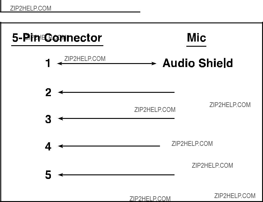
5 . 4 . 5 - P i n M i c W i r i n g D i a g r a m
 Audio +
 Audio -
 Mic Switch
 GND
GND
48

5.5. Configuraci??n del controlador del sistema PageMatrix
Como se mencion?? previamente, el controlador PageMatrix soporta simult??neamente hasta 16 estaciones de intercomunicaci??n. En las aplicaciones m??s grandes, en las que son necesarios varios controladores, las diferentes unidades del sistema PageMatrix se deben configurar con identidades m??s all?? de las 1 a 16 configuradas por defecto. Esto se logra modificando la configuraci??n de los interruptores DIP internos de la unidad.
1.Retire la placa superior del controlador (seis tornillos).
2.En el interior de la unidad, localice el interruptor DIP (denominado SW100), ubicado en la parte frontal izquierda de la misma.
3.S??lo debe ajustar los interruptores 1 y 2, seg??n la tabla de m??s abajo.
4.Los interruptores 3 a 8 est??n inactivos.
DIP SETTINGSCONTROLLER IDs
1 2 3 4 5 6 7 8
O
N
Stations 33 - 48
NOTE: Factory settings default to 1
49

5.6. Especificaciones
Controlador PageMatrix
Estaciones de intercomunicaci??n
Nivel de entrada m??ximo:
Station 4 Wallmount (de 4 botones, de pared):
Station 4 Desktop (de 4 botones, de mesa):
Station 10 Desktop (de 10 botones, de mesa):
Nivel de salida m??ximo:
Station 4 Wallmount (de 4 botones, de pared): +25 dBu
Station 4 Desktop (de 4 botones, de mesa): +25 dBu
Station 10 Desktop (de 10 botones, de mesa): +25 dBu
Impedancia de entrada:
Station 4 Wallmount (de 4 botones, de pared): 2,2K??
Station 4 Desktop (de 4 botones, de mesa): 2,2K ??
Station 10 Desktop (de 10 botones, de mesa): 2,2K ??
Impedancia de salida:
Station 4 Wallmount (de 4 botones, de pared): 200 ??
Station 4 Desktop (de 4 botones, de mesa): 200 ??
Station 10 Desktop (de 10 botones, de mesa): 200 ??
Respuesta de frecuencia:
Station 4 Wallmount (de 4 botones, de pared): 20 Hz a 20 kHz (+0 a
Station 4 Desktop (de 4 botones, de mesa): 20 Hz a 20 kHz (+0 a
Station 10 Desktop (de 10 botones, de mesa): 20 Hz a 20 kHz (+0 a
Distorsi??n arm??nica total:
Station 4 Wallmount (de 4 botones, de pared): menor que 0,01% a 1 kHz
Station 4 Desktop (de 4 botones de mesa): menor que 0,01% a 1 kHz
Station 10 Desktop (de 10 botones, de mesa): menor que 0,01% a 1 kHz
Relaci??n se??al/ruido:
Station 4 Wallmount (de 4 botones, de pared): mayor que 88 dB
Station 4 Desktop (de 4 botones, de mesa): mayor que 85 dB
Station 10 Desktop (de 10 botones, de mesa): mayor que 84 dB
Alimentaci??n fantasma:
Station 4 Wallmount (de 4 botones, de pared): +48 VCC
Station 4 Desktop de 4 botones, de mesa): +48 VCC
Station 10 Desktop (de 10 botones, de mesa): +48 VCC
Requisitos de alimentaci??n:
Station 4 Wallmount (de 4 botones, de pared): 48 mA a +24 VCC
Station 4 Desktop (de 4 botones, de mesa): 55 mA a +24 VCC
Station 10 Desktop (de 10 botones, de mesa): 92 mA a +24 VCC
Dimensiones:
Station 4 Wallmount (de 4 botones, de pared): 114,3 x 208,3 x 25,4 mm (alt. x anch. x prof.)
Station 4 Desktop de (4 botones, de mesa): 101,6 x 132,1 x 180,3 mm (alt. x anch. x prof.)
Station 10 Desktop (de 10 botones, de mesa): 101,6 x 264,2 x
50
INSTRUCCIONES DE SEGURIDAD IMPORTANTES
ADVERTENCIA: Al utilizar productos el??ctricos se deben respetar las precauciones b??sicas, que incluyen las siguientes:
1.Lea estas instrucciones.
2.Conserve estas instrucciones.
3.Preste atenci??n a todas las advertencias.
4.Respete todas las instrucciones.
5.No utilice este aparato cerca del agua. Por ejemplo, cerca o dentro de ba??eras, piscinas, lavaderos, s??tanos h??medos, etc.
6.Limpie el aparato solamente con un trapo h??medo.
7.No bloque ninguna de las aberturas de ventilaci??n. Instale el aparato de acuerdo con las instrucciones del fabricante. No debe ser coloca- do contra la pared sin separaci??n o dentro de una cubierta que impida el flujo de aire de ventilaci??n.
8.No instale el aparato cerca de fuentes de calor, tales como radiadores, registros de calefacci??n, estufas u otros aparatos que produzcan calor (incluso amplificadores).
9.No anule la funci??n de seguridad de los enchufes de tipo polarizado o con toma de tierra. El enchufe de tipo polarizado tiene dos patas planas, una m??s ancha que la otra. El enchufe con toma de tierra tiene dos patas planas y un tercer terminal de toma de tierra. La pata m??s ancha o el tercer terminal se proporcionan para su seguridad. Cuando el enchufe provisto no sirve para su recept??culo de alimentaci??n, consulte a un electricista para reemplazar el recept??culo obsoleto. No interrumpa nunca la toma de tierra. Escr??banos y solicite nuestro folleto gratuito ???Riesgo de descarga el??ctrica y puesta a tierra???. Conecte el aparato ??nicamente a una fuente de alimentaci??n del tipo mar- cado en la unidad, cerca del cable de alimentaci??n el??ctrica.
10.Proteja el cable de alimentaci??n para que no lo pise o estrangule, especialmente en los enchufes, tomacorrientes y en el punto de salida del aparato.
11.Utilice s??lo aditamentos/accesorios provistos por el fabricante.
12.Utilice s??lo carros, plataformas, tr??podes, soportes o mesas especificadas por el fabricante o vendidas con el aparato. Cuando se utiliza un carro, sea precavido al mover la combinaci??n carro/aparato, para evitar lesiones en caso de vuelcos.
13.Desenchufe este aparato durante tormentas el??ctricas o mientras no se lo utilice durante per??odos prolongados.
14.Conf??e todas las reparaciones a personal t??cnico calificado. Se requiere servicio cuando el aparato ha sido da??ado de alguna forma, como cuando se aver??an el cable de alimentaci??n o el enchufe, se derraman l??quidos o caen objetos dentro del aparato o el mismo se expuso a la lluvia o la humedad, no funciona normalmente o se lo dej?? caer.
15.Si este producto se monta en un bastidor para equipos, se debe instalar un soporte posterior.
16.La exposici??n a niveles de ruido extremadamente altos puede provocar p??rdidas auditivas permanentes. La susceptibilidad de los individ- uos a las p??rdidas auditivas inducidas por ruido var??a considerablemente, pero casi todos sufrir??n alguna p??rdida auditiva si se exponen a un nivel de ruido lo suficientemente intenso, durante un per??odo suficiente. La Administraci??n del Trabajo y la Salud del gobierno de los Estados Unidos (OSHA), ha especificado los siguientes niveles permitidos de exposici??n al ruido:
Seg??n la administraci??n OSHA, toda exposici??n que exceda los l??mites permitidos indicados m??s arriba, puede producir alguna p??rdida auditiva. Para evitar p??rdidas auditivas permanentes, si la exposici??n excede los l??mites precedentes cuando se opera este equipo de sonido, se deben utilizar tapones o protectores de los canales auditivos o por sobre los o??dos. Para asegurarse contra la exposici??n a niveles de presi??n sonora peligrosos, se recomienda que mientras esta unidad est?? funcionando, todas las personas expuestas a equipos capaces de producir niveles de presi??n sonora altos como este sistema amplificador, est??n protegidas mediante protectores auditivos.
??CONSERVE ESTAS INSTRUCCIONES!
51

FRAN??AIS
1. Introduction
F??licitations pour avoir eu la sagesse de choisir le syst??me PageMatrix??? pour vos projets de t??l??appel actuels et futurs. Utilis?? en conjonction avec notre syst??me audio num??rique MediaMatrix?? universellement acclam??, le PageMatrix constitue une approche int??gr??e et souple pour toutes les applications de t??l??appel s??rieuses.
Le MediaMatrix sert de processeur central pour l???ensemble du projet, contr??lant la totalit?? du syst??me, de l???acheminement des signaux ?? la gestion des appels. Le syst??me PageMatrix offre des postes d???appel multiples et faciles ?? configurer pour pratiquement n???importe quel besoin d???appel ou de zone. De plus, les postes d???appel sont portatifs, ce qui veut dire que les prises murales ou ports sur lesquels ils sont branch??s prennent leur identit??.
Les composants mat??riels du PageMatrix sont le contr??leur ?? double espace de baie et trois types de postes d???appel. Le contr??leur PageMatrix, qui peut alimenter jusqu????? 16 postes d???appel dans n???importe quelle combinaison, se branche sur les bo??tes de distribution pour l???audio et sur le port s??rie
Les composants logiciels sont:
???Le logiciel PageMatrix
???Les fichiers de visualisation MediaMatrix
???Les fichiers d???appel (correspondant aux fichiers de visualisation) MediaMatrix PASHA???
L???application PageMatrix permet de programmer de mani??re graphique les touches de pr??s??lection de zone pour chaque poste connect??. Une fois la configuration finalis??e, elle est simplement t??l??charg??e dans le contr??leur PageMatrix et le syst??me est pr??t ?? l???emploi. Il n???est alors plus n??cessaire d???acc??der ?? l???application PageMatrix sauf pour modifier la configuration.
Caract??ristiques
???99 zones d???appel disponibles
???16 appels simultan??s
???N???importe quelle combinaison de postes ?? quatre ou dix touches peut ??tre utilis??e.
???Tous les postes sont dot??s de DEL multicolores indiquant l?????tat de la zone pr??s??lectionn??e.
???Le contr??leur est pourvu d???une entr??e d???alimentation pour t??l??commande +24 V c.c.
???Des connecteurs Phoenix servent ?? raccorder des appareils audio aux bo??tes de distribution du MediaMatrix.
52

???Quatre syst??mes MediaMatrix peuvent ??tre raccord??s au contr??leur.
???Le panneau avant du contr??leur est dot?? de 16 DEL indiquant l?????tat des postes.
2.Description des composants mat??riels
2.1 Contr??leur PageMatrix
Le contr??leur PageMatrix constitue le coeur du syst??me. Il est reli?? par un port s??rie
Le contr??leur PageMatrix peut commander jusqu????? 16 postes de t??l??appel, ?? savoir des mod??les Station
Panneau avant
1.DEL d?????tat de poste: (16) s???allument en vert une fois que le logiciel est activ??.
2.DEL de contr??le: (4) s???allument en vert lorsque les ports de donn??es de contr??le sont en cours d???utilisation.
3.DEL d???erreur: s???allume pour indiquer une erreur lors du t??l??chargement de la configuration du logiciel PageMatrix dans le contr??leur. Lorsque ce signal se produit, t??l??chargez de nouveau la configuration.
4.DEL de donn??es: s???allume pour indiquer qu???un transfert de donn??es vers l???appareil est en cours ou que des donn??es valides se trouvent en m??moire ?? la mise sous tension.
5.DEL d???alimentation: indique que l???appareil est sous tension.
53

Panneau arri??re
6.Port de programmation
7.Ports de donn??es de contr??le (4 jacks
8.Entr??es de postes (16 jacks RJ45): tous les postes sont reli??s ?? l???une de ces 16 entr??es au moyen d???un c??ble CAT 5 standard. Le c??ble est porteur des signaux audio entre l???appareil et les postes, ainsi que de l???alimentation des postes. Remarque: ceci n???est pas une connexion de r??seau.
9.Sorties audio: l???appareil comporte quatre connecteurs de type ???Phoenix??? amovibles pour le
branchement des c??bles audio sur la bo??te de distribution. Remarque: deux bo??tes de distribution sont n??cessaires si 16 postes sont utilis??s.
10.Entr??e d???alimentation de poste: entr??e +24 V c.c. pour l???alimentation de secours des postes.
Remarque: En cas de coupure de l???alimentation du contr??leur de t??l??appel, l???alimentation de secours ne fournira de courant aux postes que pour permettre le passage du signal audio en cas d???urgence. Dans ce cas, les postes ne pourront pas communiquer avec le contr??leur et
11.Commutateur d???alimentation: permet d???allumer ou d?????teindre l???appareil.
12.Connecteur de cordon d???alimentation amovible
13.Fusible: 1A ?? 100 V/120 V c.a.~, T1A/250 V
500 mA ?? 230 V c.a~, T 500 mA/250 V
54

2.2. Poste de t??l??appel ?? montage mural Station
Le Station
Panneau avant
Touches de pr??s??lection de zone avec DEL (4):
Ces touches permettent d???activer les quatre zones pr??s??lectionn??es. Une DEL verte indique que la zone est libre alors qu???une DEL rouge signifie qu???elle est occup??e par un autre poste. La DEL clignote pour confirmer la s??lection.
Entr??e microphone ?? cinq broches:
Permet le branchement du microphone ?? main ?? 5 broches fourni.
Volume microphone:
Vis de r??glage en retrait situ??e ?? droite de l???entr??e microphone. Utilisez un petit tournevis pour r??gler le volume.
Panneau arri??re
Connecteur ?? 3 broches:
Sortie de signal audio analogique ?? raccorder au contr??leur PageMatrix. Voir le sch??ma de c??blage ?? l???annexe 5.3.
Connecteur ?? 4 broches:
Ce c??ble est porteur des donn??es ??chang??es avec le contr??leur PageMatrix et du courant d???alimentation du poste. Voir le sch??ma de c??blage ?? l???annexe 5.3.
55
Fonctionnement du poste Station
???La couleur des DEL indique l?????tat de chacune des zones pr??s??lectionn??es.
???La couleur verte indique que la zone n???est pas utilis??e par un autre poste et qu???elle est donc libre.
???La couleur rouge indique que la zone est occup??e.
???Lorsque le bouton d???alternat est enfonc??, la DEL de la zone s??lectionn??e devient orange, indiquant qu???elle est active. Les DEL des autres postes reli??s au syst??me sont ROUGES pour confirmer que la zone en question est en usage.
???Appuyez sur la touche de n???importe quelle zone pour la s??lectionner. Sa DEL clignote pour confirmer la s??lection.
????? la mise sous tension et au bout d???une minute d???inactivit??, l???appareil passe automatiquement ?? la zone 1 (d??faut).
???L???entr??e ?? 5 broches du microphone ?? main est activ??e en appuyant sur le bouton d???alternat.
???Les pr??s??lections de zone peuvent ??tre identifi??es dans les cases blanches appropri??es.
???Si toutes les DEL clignotent en rouge lors de la mise sous tension, cela signifie que le poste n???a pas ??t?? programm??.
???Si toutes les DEL clignotent en vert lors de la mise sous tension, cela signifie que le poste a ??t?? programm??.
Au sujet des pr??s??lections de zone
Le logiciel MediaMatrix d??finit les zones, lesquelles peuvent ??tre constitu??es soit d???une sortie unique, soit d???un groupe de sorties. Il sert ?? programmer les affectations de touches des postes de t??l??appel, permettant ?? chacune des touches d???acc??der ?? une ou plusieurs zones. Nous appelons ces affectations de boutons ???pr??s??lections de zone??? car ces param??tres sont d??finis ?? l???avance. Les pr??s??lections de zone sont ensuite t??l??charg??es dans le contr??leur PageMatrix, o?? elles deviennent actives.
Au sujet de la priorit??
Aucun r??glage prioritaire n???est initialement programm?? dans le syst??me PageMatrix. N???importe que microphone peut ??tre utilis?? ?? tout moment et l???indication ???occup????? par une DEL signifie que la zone est occup??e par un autre poste. Toutefois, des niveaux de priorit?? complexes peuvent ??tre configur??s et int??gr??s au syst??me.
56

2.3. Poste de t??l??appel de bureau Station Four???
Le Station Four??? est un poste de t??l??appel de bureau ?? quatre touches comprenant un microphone ?? condensateur ??lectret. Chacune des quatre pr??s??lections de zone est d??finie et programm??e par le logiciel PageMatrix.
Panneau avant
Alternat:
Appuyez sur ce bouton et
Touches de zones avec DEL (4):
Ces touches permettent d???activer les quatre zones pr??s??lectionn??es. Une DEL verte indique que la zone est libre alors qu???une DEL rouge signifie qu???elle est occup??e par un autre poste. La DEL clignote pour confirmer la s??lection.
Entr??e microphone XLR:
Entr??e de microphone ?? alimentation duplex
Volume du microphone:
R??glage de gain en retrait
Panneau arri??re
Entr??e microphone auxiliaire ?? 5 broches
Destin??e au branchement d???un microphone ?? distance dot?? d???un alternat. Voir le sch??ma de c??blage ?? l???annexe 5.4. Le microphone auxiliaire est automatiquement achemin?? ?? la pr??s??lection de zone 1.
Fonctionnement du poste Station Four
???La couleur des DEL indique l?????tat de chacune des zones pr??s??lectionn??es.
???La couleur verte indique que la zone n???est pas utilis??e par un autre poste et est par con s??quent libre.
???La couleur rouge indique que la zone est occup??e.
???Lorsque le bouton d???alternat est enfonc??, la DEL de la zone s??lectionn??e devient orange, indiquant qu???elle est active. Les DEL des autres postes reli??s au syst??me sont ROUGES pour confirmer que la zone en question est en cours d???utilisation.
???Appuyez sur la touche de n???importe quelle zone pour la s??lectionner. Sa DEL clignote pour confirmer la s??lection.
????? la mise sous tension et au bout d???une minute d???inactivit??, l???appareil passe automatiquement ?? la zone 1 (d??faut).
???Les pr??s??lections de zone peuvent ??tre identifi??es dans les cases blanches appropri??es.
???Si toutes les DEL clignotent en rouge lors de la mise sous tension, cela signifie que le poste n???a pas ??t?? programm??.
57
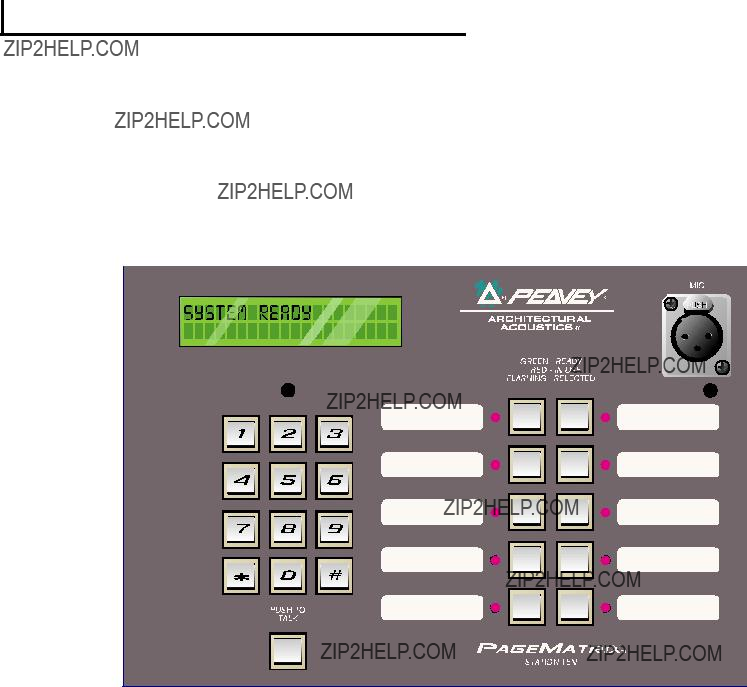
???Si toutes les DEL clignotent en vert lors de la mise sous tension, cela signifie que le poste a ??t?? programm??.
???L???entr??e de microphone auxiliaire (panneau arri??re) est toujours achemin??e ?? la pr??s??lection de zone 1.
2.4.Poste de t??l??appel de bureau Station Ten???
Le Station Ten??? est un poste de t??l??appel de bureau ?? dix touches comprenant un microphone ?? condensateur ??lectret. Chacune des dix pr??s??lections de zone est d??finie et programm??e par le logiciel PageMatrix. En outre, le poste est dot?? d???un clavier ?? 12 touches style ???t??l??phone??? et d???un ??cran ACL 20 x 2 pour la s??lection et le contr??le de 99 zones ???virtuelles??? possibles. La programmation des 10 touches de s??lection est diff??rente pour chaque poste; toutefois, les 89 zones d???acc??s par composition ???virtuelle??? sont les m??mes (globales) pour chaque poste Station Ten reli?? au contr??leur PageMatrix. Chacune des pr??s??lections de zone est d??finie et programm??e par le logiciel PageMatrix.
Panneau avant
Bouton d???alternat:
Appuyez sur ce bouton pour activer le microphone de la zone pr??s??lectionn??e.
Touches de pr??s??lection de zone avec DEL (10):
Ces touches permettent d???activer chacune des dix zones pr??s??lectionn??es. Une DEL verte indique que la zone est libre alors qu???une DEL rouge signifie qu???elle est occup??e par un autre poste. La DEL clignote pour confirmer la s??lection.
Entr??e de microphone XLR:
Entr??e de microphone ?? alimentation duplex.
Volume microphone:
Commande de gain de microphone en retrait.
58
Panneau arri??re
Entr??e microphone auxiliaire ?? 5 broches:
Destin??e au branchement d???un microphone ?? distance dot?? d???un alternat. Voir le sch??ma de c??blage ?? l???annexe 5.4. Le microphone auxiliaire est automatiquement achemin?? ?? la pr??s??lection de zone 1.
Connecteur RJ45:
Pour le branchement du contr??leur PageMatrix.
Fonctionnement du poste Station Ten
???La couleur des DEL indique l?????tat de chacune des zones pr??s??lectionn??es.
???La couleur verte indique que la zone n???est pas utilis??e par un autre poste et est par cons??quent libre.
???La couleur rouge indique que la zone est occup??e.
???Lorsque le bouton d???alternat est enfonc??, la DEL de la zone s??lectionn??e devient orange, indiquant qu???elle est active. Les DEL des autres postes reli??s au syst??me sont ROUGES pour confirmer que la zone en question est en cours d???utilisation.
???Appuyez sur la touche de n???importe quelle zone pour la s??lectionner. Sa DEL clignote pour confirmer la s??lection.
????? la mise sous tension, l???appareil passe automatiquement ?? la zone 1 (d??faut).
???L???entr??e de microphone auxiliaire (5 broches) du panneau arri??re est programm??e pour la zone pr??s??lectionn??e 1.
???Le clavier peut ??tre utilis?? pour acc??der directement ?? la zone pr??s??lectionn??e. Il suffit d???entrer un num??ro ?? un ou deux chiffres et d???appuyer sur # pour la s??lectionner.
???Le nom de la zone s??lectionn??e (un nom de 16 caract??res maximum peut ??tre d??fini par l???utilisateur dans le logiciel PageMatrix) s???affiche sur l?????cran ACL 20 x 2, accompagn?? de l?????tat (pr??te/occup??e/appel)
???La premi??re ligne de l???affichage indique le nom et l?????tat du poste, la seconde le nom de la zone.
???Les pr??s??lections de zone peuvent ??tre identifi??es dans les cases blanches appropri??es.
???Si toutes les DEL clignotent en rouge lors de la mise sous tension, cela signifie que le poste n???a pas ??t?? programm??.
???Si toutes les DEL clignotent en vert lors de la mise sous tension, cela signifie que le poste a ??t?? programm??.
????? la mise sous tension et au bout d???une minute d???inactivit??, l???appareil passe automatiquement ?? la zone 1 (d??faut).
Au sujet des pr??s??lections de zone
Le logiciel MediaMatrix d??finit les zones, lesquelles peuvent ??tre constitu??es soit d???une sortie unique, soit d???un groupe de sorties. Il sert ?? programmer les affectations de touches du poste de t??l??appel, permettant ?? chacune des touches d???acc??der ?? une ou plusieurs zones. Nous appelons ces affectations de boutons ???pr??s??lections de zone??? car ces param??tres sont d??finis ?? l???avance. Les pr??s??lections de zone sont ensuite t??l??charg??es dans le contr??leur PageMatrix, o?? elles deviennent actives.
Au sujet de la priorit??
Aucun r??glage prioritaire n???est initialement programm?? dans le syst??me PageMatrix. N???importe que microphone peut ??tre utilis?? ?? tout moment et l???indication ???occup????? par une DEL signifie que la zone
59

est occup??e par un autre poste. Toutefois, des niveaux de priorit?? complexes peuvent ??tre configur??s et int??gr??s au syst??me.
2 . 4 . T y p i c a l P a g e M a t r i x C o n n e c t i o n
Up to 16 Stations of any combination
CAT 5 STANDARD ???Data Type??? cable is used.
However, there is voltage on the line. DO NOT
CONNECT to computer networks.
Station 4W???
CAT 5*
Cable
MediaMatrix??
Cable
BoB Cable
IA??? 200
CAT 5*
Cable
PageMatrix???
Audio
Cable
Lap Top
OR
MediaMatrix??
Com Port
60
3. Description du logiciel PageMatrix
3.1. Mat??riel requis
Minimum: PC
3.2. Installation du logiciel
Remarque: sur les syst??mes MediaMatrix Mainframe ?? partir du mod??le 1999, l???application MediaMatrix est d??j?? install??e. Les instructions
Le syst??me logiciel PageMatrix complet inclut:
1.L???application PageMatrix (disquette 1)
2.Les fichiers de visualisation MediaMatrix et PASHA??? (disquette 2)
3.Les utilitaires MediaMatrix (disquette 2)
Premi??re ??tape : Installation du logiciel PageMatrix (les fichiers par d??faut sont entre parenth??ses)
A.Ins??rez la disquette 1 (PageMatrix Installation) dans l???unit?? de disquette.
B.Ex??cutez ???A:\setup.exe???.
C.Le logiciel demande d???indiquer un r??pertoire d???installation (c:\pagemtrx) et un nom de groupe de programmes (PageMatrix). Il installe les fichiers dans le r??pertoire sp??cifi?? et cr??e un groupe de programmes. Lorsque la phrase ???Installation Complete!???(installation termin??e) s???affiche en rouge dans la fen??tre d???installation, cliquez sur le bouton Finish (terminer) ou, s???il n???appara??t pas, sur le bouton Cancel (annulation). Il n???est pas n??cessaire de relancer l???ordinateur apr??s avoir install?? le logiciel.
Deuxi??me ??tape : Installation des fichiers de visualisation MediaMatrix:
Remarque: Lors de l???installation des fichiers de visualisation et utilitaires PageMatrix, il est n??cessaire de savoir dans quel r??pertoire le logiciel MediaMatrix se trouve (s???il est plac?? dans un r??pertoire autre que celui sp??cifi?? en usine).
A.Ins??rez la disquette 2 (fichiers de visualisation MediaMatrix) dans l???unit?? de disquette.
B.Ex??cutez ???A:\views.exe???.
C.Ce fichier zip ?? extraction automatique demande le nom du r??pertoire o?? placer les fichiers d??compress??s. Bien que ces fichiers puissent ??tre plac??s n???importe o?? sur le disque dur, nous recommandons de les installer dans le
D.Une fois le r??pertoire confirm??, cliquez sur Unzip (d??compresser).
E.Lorsque l???installation est termin??e, cliquez sur Close (fermer).
Troisi??me ??tape : Installation des utilitaires MediaMatrix
A.Ins??rez la disquette 2 (MediaMatrix view Files) dans l???unit?? de disquette.
B.Ex??cutez ???A:\devices.exe???.
C.Ce fichier zip ?? extraction automatique demande le nom du r??pertoire o?? placer les fichiers d??compress??s. Ces fichiers DOIVENT ??tre install??s dans le
61
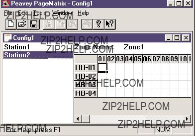
r??pertoire racine est diff??rent de celui sp??cifi?? en usine,
D.Une fois le r??pertoire confirm??, cliquez sur Unzip (d??compresser).
E.Lorsque l???installation est termin??e, cliquez sur Close (fermer).
3.2.1.Lancement de PageMatrix
Windows 95:
1.Dans le menu Start (D??marrer) s??lectionnez Programs (Programmes).
2.S??lectionnez le r??pertoire PageMatrix.
3.S??lectionnez PageMatrix.
Windows 3.1:
1.Trouvez le groupe de programmez PageMatrix dans le gestionnaire de programmes.
2.Cliquez deux fois sur le groupe, puis deux fois sur l???ic??ne PageMatrix.
Remarque: Le lanceur de programme MediaMatrix peut ??tre utilis?? pour les syst??mes dans lesquels le logiciel PageMatrix n???a pas ??t?? charg??. Ce lanceur de programme se trouve dans le menu Device/Miscellaneous (Utilitaires/divers) de MediaMatrix. Voir l???annexe 5.2.
3.2.2. Postes et zones
L???application PageMatrix simplifie le processus de programmation des postes distants. Une matrice ?? grille s???affiche, indiquant chaque bouton utilis?? pour le poste s??lectionn??. La mention HB repr??sente une touche mat??rielle et le num??ro qui la suit est celui de la touche sur le poste. Les touches de poste sont affich??es en rangs et les affectations de zones potentielles, en colonnes.
Pour affecter une touche, il suffit de cliquer deux fois sur la zone d??sir??e avec le bouton gauche de la souris (la s??lection est alors encadr??e), puis de cliquer sur le bouton droit pour confirmer.
Les zones repr??sentent les appareils physiques connect??s via les sorties de bo??tes de connexion MediaMatrix, amplificateurs et
Programmation des postes de t??l??appel au moyen de l???application PageMatrix
[Remarque : voir le chapitre suivant (Barre de menu) pour des informations compl??mentaires]
Choisissez l???option ???Insert Station??? (ins??rer poste) ou ???Add Station??? (ajouter poste) dans le menu Edit (??dition) pour inclure vos postes mat??riels dans la programmation. Une fois l???application PageMatrix configur??e, une colonne listant tous les postes de t??l??appel branch??s s???affiche sur la partie gauche de l?????cran. Sur la droite, en haut, appara??t une matrice des zones et des colonnes de touches par num??ro. S??lectionnez d???abord le poste ?? programmer, puis activez les zones pour chaque touche ?? l???aide de la souris. Une fois l???op??ration termin??e, t??l??chargez la configuration dans le contr??leur PageMatrix (menu File [Fichiers]). Les touches des postes de t??l??appel sont maintenant programm??es et pr??tes ?? l???emploi.
62

Noms des pr??s??lections de zone avec le poste Station Ten
Le poste Station Ten est dot?? d???un affichage 20 x 2 permettant de voir les pr??s??lections de zone.
3.3. Pr??sentation de la barre de menu de l???application PageMatrix
3.3.1 Menu File (Fichier)
New (nouveau)
Cette option ouvre une nouvelle configuration d??finie avec les param??tres par d??faut.
Open (ouvrir)
Cette option affiche la bo??te de dialogue d???ouverture de fichier standard, qui permet d???acc??der ?? un fichier existant (*.pmx).
Close (fermer)
Ferme la configuration active.
Save (enregistrer)
Enregistre la configuration actuelle et les modifications ??ventuellement faites.
Save As (enregistrer sous)
Affiche la bo??te de dialogue d???enregistrement de fichier standard, qui permet de changer le nom du fichier avant de le sauvegarder.
Print (Imprimer)
Option non activ??e.
Print Preview (aper??u avant impression)
Option non activ??e.
Print Setup... (configurer impression)
Option non activ??e.
Download Configuration... (t??l??charger configuration)
Cette option permet d???envoyer les param??tres de configuration au contr??leur PageMatrix. ??tant donn?? que la nouvelle configuration remplace celle qui est d??j?? install??e dans le contr??leur, le mes- sage ???Do you wish to continue????
Recent File List (liste des fichiers r??cents)
Cette option de menu affiche la liste des configurations les plus r??centes.
Exit (quitter)
Ferme PageMatrix.
63

3.3.2. Menu Edit (??dition)
Undo (Annuler)
Option non activ??e.
Cut (D??couper)
Option non activ??e.
Copy (Copier)
Option non activ??e.
Paste (Coller)
Option non activ??e.
Insert Station (Ins??rer Poste)
Cette option permet de cr??er un nouveau poste de t??l??appel pouvant ??tre modifi??. Elle se trouve dans la liste avant le poste actuellement s??lectionn??.
Station Name (nom de poste): jusqu????? 16 caract??res.
Number of buttons (nombre de touches) : 4 ou 10.
PAC Port (port PAC): identifie le port (1 ??16) du contr??leur PageMatrix auquel le poste est reli??.
PAC Port Address (adresse du port PAC): jusqu????? pr??sent toujours r??gl??e sur 1.
Add Station (ajouter poste)
Cette option permet de cr??er un nouveau poste de t??l??appel pouvant ??tre modifi??. Elle se trouve ?? la fin de la liste.
Station Name (nom de poste): jusqu????? 16 caract??res.
Number of buttons (nombre de touches): 4 ou 10.
PAC Port (port PAC): identifie le port (1 ??16) du contr??leur PageMatrix auquel le poste est reli??.
PAC Port Address (adresse du port PAC): jusqu????? pr??sent toujours r??gl??e sur 1.
Delete Station (supprimer poste)
Cette option permet de supprimer le poste actuellement s??lectionn??. Le message ???Are You Sure???
64

3.3.3.Menu Tools/Options (outils/options)
View Toolbar (Afficher Barre D???outils)
Permet d???afficher ou de cacher la barre d???outils.
View Status Bar (Afficher Barre
D?????tat)
Permet d???afficher ou de cacher la barre d?????tat au bas de l?????cran.
View Station Addresses (Afficher
Adresses Des Postes)
Permet d???afficher l???adresse d???un poste, devant son nom.
Max Number of Zones (Nombre Maximum De Zones)
Ce param??tre d??finit le nombre maximum de zones utilis??es avec le syst??me.
Communications
Permet de configurer le port de t??l??chargement (ports COM 1 ?? 4). Une option de programmation hors ligne est ??galement disponible pour l???op??ration ?? distance.
3.3.4. Menu Windows (Fen??tres)
New Window (Nouvelle Fen??tre)
Permet de cr??er une nouvelle fen??tre.
Cascade
Fonction Window standard permettant de disposer toutes les fen??tres de configuration ouvertes en cascade.
Tile (Juxtaposition)
Fonction Window standard permettant de juxtaposer toutes les fen??tres de configuration ouvertes.
Arrange Icons (Arrangement Ic??nes)
Permet d???aligner toutes les fen??tres filles r??duites.
Configuration Display (Affichage Des Configurations)
Liste toutes les configurations ouvertes.
3.3.5. Menu Help (Aide)
About PageMatrix (au sujet de PageMatrix)
Affiche l?????cran initial de PageMatrix.
65

4.0.Fonctionnement de PageMatrix
4.1.G??n??ralit??s
4.1.1. Composants
Les syst??mes PageMatrix / MediaMatrix sont constitu??s de cinq composants principaux :
???Au moins un poste de t??l??appel PageMatrix reli?? au contr??leur par un c??ble de cat??gorie cinq ad??quat
???Un contr??leur PageMatrix dans lequel le fichier de configuration appropri?? est charg??
???Le logiciel d???application PageMatrix
???Un syst??me audio MediaMatrix pilot?? par PASHA
???Un fichier PASHA.ini configur?? pour le ???fichier de visualisation??? ??tabli
4.1.2.Connexions
Les postes de t??l??appel sont reli??s au contr??leur PageMatrix par c??ble CAT 5. Ce c??ble est porteur de trois ???signaux???: le signal audio analogique du microphone, la tension requise pour l???alimentation du poste de t??l??appel ?? distance, et le signal des donn??es de contr??le en s??rie qui d??terminent o?? le signal du microphone est achemin?? par le MediaMatrix.
Les sorties de signal analogique de microphone de tous les postes de t??l??appel, ?? l???arri??re du contr??leur PageMatrix, sont individuellement reli??es aux entr??es des bo??tes de distribution MediaMatrix.
L???une des sorties s??rie ?? l???arri??re du contr??leur PageMatrix est reli??e ?? l???un des ports de communications ?? l???arri??re du ch??ssis MediaMatrix.
4.1.3. Postes de t??l??appel de bureau (mod??les Station Four et Station Ten)
Il n???y a pas de commutation locale des microphones branch??s sur les postes de t??l??appel. Quel que soit le mod??le, le microphone est activ?? en permanence. Les touches de postes commandent uniquement la communication s??rie du contr??leur PageMatrix.
4.1.4. Contr??leur PageMatrix
Cet appareil remplit trois fonctions:
1: Il fournit l???alimentation des postes de t??l??appel.
66
2:Il achemine les signaux analogiques de microphone des postes de t??l??appel aux entr??es des bo??tes de distribution du contr??leur MediaMatrix.
3:Il analyse les donn??es de contr??le de chaque poste de t??l??appel et les convertit en cha??nes de donn??es standard pouvant ??tre transmises au contr??leur MediaMatrix.
Les signaux de microphone des postes de t??l??appel ne sont pas trait??s par le contr??leur PageMatrix mais le traversent simplement tels qu???ils sont re??us. Toutes les op??rations de commutation ou d???acheminement sont effectu??es par le MediaMatrix.
4.1.4. Syst??me MediaMatrix et PASHA
Parmi les nombreuses t??ches qu???il remplit, le syst??me MediaMatrix re??oit les signaux analogiques des postes de t??l??appel via le contr??leur PageMatrix, les convertit en signaux num??riques et effectue toutes les op??rations de traitement, y compris leur acheminement vers les diff??rentes ???zones???. Ces fonctions d???acheminement sont ex??cut??es par des utilitaires sp??ciaux du syst??me se trouvant dans son ???fichier de visualisation???, lesquels sont contr??l??s ?? partir du contr??leur PageMatrix via PASHA.
4.1.5. Bouton d???alternat ??? Comment
1:Les touches de pr??s??lection de zones permettent de s??lectionner les zones configur??es dans le contr??leur MediaMatrix.
2:Lorsque le bouton d???alternat est enfonc??, le contr??leur MediaMatrix envoie imm??diatement la commande s??rie appropri??e au port de communications du MediaMatrix. (La commande s??rie est pr??d??finie par le fichier de configuration du PageMatrix t??l??charg?? dans le contr??leur et utilis?? par
3:Cette commande s??rie est interpr??t??e par le MediaMatrix (via PASHA) et ???appuie??? sur les touches d???acheminement dans le fichier de visualisation du MediaMatrix pour envoyer le signal audio ?? la zone ou au groupe de zones s??lectionn??es par le poste de t??l??appel.
4:Le signal audio est transmis ?? la zone (ou aux zones) via le contr??leur MediaMatrix tant que le bouton d???alternat du poste est maintenu enfonc??.
5:Les fonctions telles que les priorit??s d???appel, l?????vitement des sources de signal, l?????galisation de zone, etc., sont toutes des fonctions du contr??leur MediaMatrix et ne sont pas directement trait??es par les composants du syst??me PageMatrix.
4.1.6. Fonctionnement du MediaMatrix
Les syst??mes de t??l??appel peuvent ??tre des syst??mes complexes constitu??s de plusieurs ???routeurs de mixage???. Par exemple, la programmation d???un syst??me comprenant 8 postes et 32 touches exige l?????criture d???un fichier PASHA portant sur chacun des emplacements de matrice (256 param??tres). ??tant donn?? que la programmation de vos propres fichiers PASHA exigerait trop de temps, nous avons pr??par?? un assortiment de fichiers de visualisation et de fichiers d???ini tialisation PASHA.INI pour vous faciliter la t??che. Nous vous recommandons vivement d???utiliser ces fichiers fournis sur disquette et de les modifier en fonction de votre application.
67
Utilisation de base ??? Tout d???abord...
1.Trouvez le fichier .txt pour le syst??me que vous d??sirez utiliser.
2.Donnez ce fichier le nom Pasha.ini et
Remarque : Pour conserver le fichier pasha.ini existant, il suffit de le renommer.
3.Ouvrez MediaMatrix (s???il n???est pas d??j?? lanc??).
4.Dans le menu Device (syst??mes), s??lectionnez ???Paging??? (t??l??appel) pour voir les syst??mes disponibles.
5.Choisissez un syst??me existant et
6.Testez les acheminements et les zones.
Exemple:
Supposons que vous d??sirez utiliser le fichier 1632.pav. Remplacez son nom par pasha.ini, puis
4.2. D??pannage 101
???N???oubliez pas que le fichier de visualisation doit ??tre compil??.
???
???Veillez ?? initialiser PageMatrix et ?? programmer un fichier de test.
???Dans MediaMatrix, observez les indicateurs visuels du fichier de visualisation pour d??terminer si le syst??me r??pond.
???Enfin, v??rifiez le type de c??blage, les connexions et la configuration des ports.
68

5. Annexe
5.1. Assistance d???usine
Peavey offre des services d???assistance client??le et de r??parations directement ?? l???usine. N???h??sitez pas ?? nous appeler si vous d??sirez notre aide ou des informations compl??mentaires. Vous pouvez nous joindre de 8 ?? 17 heures HNC au (800)
Peavey Electronics Corp. ??? MediaMatrix Support Group ??? 711 A St. ??? Meridian, MS 39301 ???
Vous pouvez ??galement obtenir, 24 heures sur 24 et sept jours sur sept, des conseils utiles, fiches techniques, r??ponses aux questions souvent pos??es, notes d???applications et autres informations concernant les produits Peavey Architectural Acoustics sur notre site web, ?? l???adresse suivante:
http://www.peavey.com/division/arch/index.html
Pour vous offrir le meilleur soutien technique possible, il nous sera sans doute n??cessaire de voir votre fichier de visualisation afin de pouvoir diagnostiquer pr??cis??ment votre probl??me. Cela contribuera ??galement ?? faciliter votre travail et ?? accro??tre l???efficacit?? de votre syst??me. Gr??ce ?? Internet et au courrier ??lectronique, vous pourrez redevenir op??rationnel dans de brefs d??lais. Envoyez votre message ??lectronique accompagn?? du fichier de visualisation ??:
George Douglas, directeur national des ventes ?? george@peavey.com
Ken Valentine, directeur du district central ?? ken@peavey.com
Will Roland, directeur du district ouest ?? will@peavey.com
Joel Moak, directeur du district
Levin Culpepper, coordinateur du soutien technique international ?? levin@peavey.com
Brent Harshbarger, directeur des produits ?? brent@peavey.com
En cas d???urgence en dehors des heures de bureau ou pendant le
ARCHITECTURAL ACOUSTICS??
711 A Street ??? Meridian, MS 39301 ???
Les fonctions et caract??ristiques sont sujettes ?? changements sans pr??avis.
69

5.2 Utilisation du lanceur de programme MediaMatrix
Le lanceur de programme se trouve dans le menu Device/Miscellaneous (syst??me/divers). Il permet d???ouvrir facilement une autre application Windows pendant l???utilisation de MediaMatrix. Le bloc de lanceur de programme peut ??tre ??tiquet?? et inclus dans n???importe quelle fen??tre d???un programme MediaMatrix. Le lanceur de programme peut soit lancer une autre application Window???, soit passer ?? cette application si elle est d??j?? ouverte. La bo??te de dialogue Object Properties (propri??t??s objet) de ce programme comporte un champ intitul?? ???Run this program??? (ex??cuter ce programme) qui contient le chemin d???acc??s complet et le nom de fichier, ainsi que les arguments de ligne de commande du programme que vous d??sirez ex??cuter. Vous pouvez parcourir les applications en cours en appuyant sur le bouton ???Window Title...??? (titre de fen??tre) et les fichiers ex??cutables (*.exe) en appuyant sur le bouton ???File Name???(nom de fichier). L???objet peut alors soit ex??cuter l???application en cours, soit passer ?? une autre application par un clic simple ou double de la souris selon le r??glage des touches radio ???Run Program on???(ex??cuter programme sur). En mode d?????dition, l???action est toujours command??e par un double clic.
70
5 . 3 . S t a t i o n 4 - W W i r i n g D i a g r a m
1
 485+
485+
2 
 485 -
485 -
3 
 GND
GND
4 
 24V+
24V+
5 
 GND
GND
CAT 5
54
NOTE:
This is not a network connection.
71

5.4.
 Audio +
 Audio -
 Mic Switch
 GND
GND
72

5.5. Configuration du contr??leur PageMatrix
Comme il l???a ??t?? mentionn?? plus haut, le contr??leur PageMatrix peut commander jusqu????? 16 postes simultan??ment. Dans les applications plus ??tendues o?? il est n??cessaire d???utiliser plusieurs contr??leurs, les codes d???identification des diff??rentes unit??s PageMatrix peuvent ??tre configur??s
1.Retirez la plaque du dessus du contr??leur (six vis).
2.Regardez ?? l???int??rieur de l???appareil pour trouver le commutateur DIP (marqu?? SW100), situ?? sur le c??t?? avant gauche du contr??leur.
3.Seuls les interrupteurs 1 et 2 doivent ??tre r??gl??s, conform??ment au tableau
4.Les interrupteurs 3 ?? 8 sont inactifs.
DIP SETTINGSCONTROLLER IDs
1 2 3 4 5 6 7 8
O
N
Stations 33 - 48
NOTE: Factory settings default to 1
73

5.6. Fiche technique
Postes de t??l??appel
Niveau d???entr??e maximum:
Station 4 ?? montage mural:
Station 4 de bureau:
Station 10 de bureau:
Niveau de sortie maximum:
Station 4 ?? montage mural: +25 dBu
Station 4 de bureau: +25 dBu
Station 10 de bureau: +25 dBu
Imp??dance d???entr??e:
Station 4 ?? montage mural: 2,2 K ohms
Station 4 de burea : 2,2 K ohms
Station 10 de bureau: 2,2 K ohms
Imp??dance de sortie:
Station 4W ?? montage mural : 200 ohms
Station 4 de bureau: 200 ohms
Station 10 de bureau: 200 ohms
R??ponse en fr??quence:
Station 4 ?? montage mural: 20 Hz ?? 20 kHz (+0,
Station 4 de bureau: 20 Hz ?? 20 kHz (+0,
Station 10 de bureau: 20 Hz ?? 20 kHz (+0,
Distorsion harmonique totale:
Station 4 ?? montage mural: moins de 0,01 % ?? 1 kHz
Station 4 de bureau: moins de 0,01 % ?? 1 kHz
Station 10 de bureau: moins de 0,01 % ?? 1 kHz
Rapport
Station 4 ?? montage mural: sup??rieur ?? 88 dB
Station 4 de bureau: sup??rieur ?? 85 dB
Station 10 de bureau: sup??rieur ?? 84 dB
Alimentation duplex:
Station 4 ?? montage mural: +48 V c.c.
Station 4 de bureau: +48 V c.c.
Station 10 de bureau: +48 V c.c
Alimentation ??lectrique:
Station 4 ?? montage mural: 48 mA ?? +24 V c.c.
Station 4 de burea: 55 mA ?? +24 V c.c.
Station 10 de bureau: 92 mA ?? +24 V c.c.
Dimensions:
Station 4 ?? montage mural: 4,5 po H x 8,2 po W x 1 po D (11,4 x 20,8 x 2,5 cm)
Station 4 de burea : 4 po H x 5,2 po W x 7,1 po D (10,2 x 13,2 x 18 cm)
Station 10 de bureau: 4 po H x 10,4 po W x 7,1 po D (10,2 x 26,4 x 18 cm)
74
NOTE IMPORTANTE CONCERNANT LA SECURITE
ATTENTION: Lors de l???utilisation de appareils ??lectriques, certaines mesures de s??curit?? doivent ??tre respect??es:
1.Lisez toutes les instructions.
2.Conservez ces instructions.
3.Tenez compte de tous les avertissements.
4.Suivez pr??cisemment les instructions.
5.N???utilisez pas l???appareil ?? proximit?? de l???eau. Par exemple pr??s d???un bain, d???une piscine, d???un ??vier, ou dans un
6.Nettoyez avec un chiffon sec uniquement.
7.N???obstruez aucune des ventilations. Installez l???appareil selon les instructions du constructeur. Ne placez pas l???appareil contre un mur ou dans une enceinte emp??chant la libre circulation de l???air.
8.Ne placez pas l???appareil pr??s d???une source de chaleur telle un radiateur, four, cuisini??re ou tout autre appareil (amplificateur inclus) produisant de la chaleur.
9.Ne d??connectez pas la prise de terre. Cette connexion doit ??tre r??alis??e pour votre s??curit??. Si le connecteur d???alimentation ne correspond pas ?? votre prise secteur, consultez un ??lectricien qualifi??. Connectez l???appareil ?? une source de courant correspondant aux sp??cifications inscrites sur l???appareil pr??s du cordon d???alimentation ou de la prise IEC.
10.Prot??gez le cordon d???alimentation contre tout dommage, principalement pr??s de la prise ou pr??s de sa connexion avec l???appareil.
11.N???utilisez que des accessoires ou extensions fournis par le constructeur.
12.Utilisez uniquement un stand, tr??pied, crochet ou support sp??cifi?? par le constructeur ou vendu avec l???appareil.
13.D??branchez l???appareil en cas d???orage ou lors d???une
14.Fa??tes r??aliser toutes r??parations par un personnel qualifi??. Une r??paration doit ??tre effectu??e quelque soient les dommages subis par l???appareil (cordon d???alimentation ab??m??, intrusion de liquide ou d???un quelconque objet dans l???appareil, exposition aux moisissures ou ?? la pluie, fonc- tionnement anormal de l???appareil).
15.Si l???appareil est mont?? dans un rack, l???arri??re doit ??tre support?? correctement.
16.L???exposition ?? des niveaux de bruit ??lev??s peut provoquer la perte de l???ou??e. La r??action de chaque individu est diff??rente
Une exposition plus longue ?? ces niveaux de pression accoustique peut provoquer une perte certaine de l???audition. Des bouchons d???oreille, filtres ou casques
CONSERVEZ CES INSTRUCTIONS!
75

DEUTSCH
1. Einleitung
Wir begl??ckw??nschen Sie zu Ihrer klugen Entscheidung, f??r Ihren jetzigen und k??nftigen
MediaMatrix dient als Verarbeitungszentrale f??r eine vollst??ndige Anlage und steuert alle Abl??ufe ??? von der Signallenkung bis zur Rufanlagenverwaltung. Das
mehrere Rufstationen, die sich problemlos je nach Ruf- und Zonenerfordernissen praktisch beliebig konfigurieren lassen. Diese Rufstationen sind au??erdem tragbar, wobei die Wandanschlu??dose bzw. der Port die Identit??t der angeschlossenen Station bestimmt.
Zu den Komponenten der
Die Software umfa??t folgende Komponenten:
???Die
???Die
???Die MediaMatrix
Das
Merkmale
???99 verf??gbare Rufzonen
???16 Rufe simultan
???Stationen mit vier oder zehn Tasten beliebig kombinierbar
???Alle Stationen mit mehrfarbigen Leuchtdioden, die den Zonenstatus anzeigen.
???Der Controller verf??gt ??ber einen
???F??r die Anschl??sse der Audiokabel an den
???Der Controller unterst??tzt bis zu vier
???Die Frontplatte des Controllers hat 16 Leuchtdioden zur Stationsstatusanzeige.
76

2.Beschreibung der Hardware
2.1Der
Der
Der
Siehe Diagramm der Frontplatte im englischen Teil des Handbuchs pg. 6.
Frontplatte
1.
2.
3.
4.
5.Betriebsleuchte (Power): Zeigt an, da?? das Ger??t eingeschaltet ist.
77
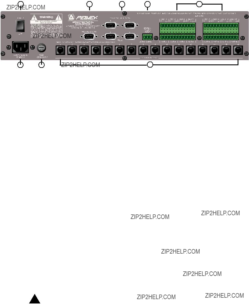
R??ckwand
6.Programmanschlu??
7.
8.Stationseing??nge (16
9.Audioausg??nge: F??r die Audioanschl??sse an einer
abnehmbare
10.
Hinweis: Sollte einmal die Stromversorgung des Rufanlagencontrollers ausfallen, versorgt der
11.Betriebsschalter: Dient zum Ein- und Ausschalten des Systems.
12.Abnehmbarer Stromkabelstecker
13.Sicherung: 1 A bei 100 V/120 V~, T1 A/250 V
500 mA bei 230 V~, T500 mA/250 V
78

2.2. Rufstation Station
Die Station
Frontplatte
4 Zonentasten mit Leuchtdioden:
Dienen zum Anw??hlen einer der vier voreingestellten Zonen. Eine gr??ne Leuchtdiode zeigt an, da?? die betreffende Zone zug??nglich ist. Eine rote Leuchtdiode bedeutet, da?? die Zone gerade von einer anderen Station aus gerufen wird. Zur Best??tigung der Wahl blinkt die Leuchtdiode.
F??nfpoliger Mikrofoneingang:
Dient zum Anschlie??en des mitgelieferten Handmikrofons mit 5 Kontakten.
Mic Volume (Lautst??rke):
Rechts vom Mikrofoneingang befindliche versenkte Schraube. Die Mikrofonverst??rkung mit einem kleinen Schraubenzieher einstellen.
R??ckwand
Dreipoliger Anschlu??:
Dies ist der Ausgang f??r das analoge Audiosignal. Dient zum Anschlie??en am PageMatrix- Controller. Siehe Schaltplan, Anhang 5.3.
Vierpoliger Anschlu??:
Dient zur ??bertragung der Steuerungsdaten vom und zum
79
Betrieb der Station
???Die Leuchtdiodenfarbe gibt den Status der jeweiligen Voreinstellzone wieder:
???Gr??n bedeutet, da?? die Zone frei ist, d.h. nicht von einer anderen Station gerufen wird.
???Rot bedeutet, da?? die Zone belegt ist.
???Dr??ckt man auf die Sprechtaste des Mikrofons (???Talk???), wird die gew??hlte Zonentaste orange und best??tigt damit die Aktivierung. Andere am System angeschlossene Stationen zeigen die entsprechende Zonentaste ROT an und signalisieren damit, da?? die Zone belegt ist.
???Zum W??hlen einer Zone dr??ckt man auf die entsprechende Taste. Zur Best??tigung der Wahl blinkt die Leuchtdiode.
???Beim Einschalten sowie nach einmin??tiger Inaktivit??t schaltet das Ger??t automatisch auf Zone eins um.
???Der f??nfpolige Eingang des Handmikrofons wird durch Dr??cken der Sprechtaste (???Talk???) aktiviert.
???Zum Beschriften der Voreinstellzonen sind wei??e Felder vorgesehen.
???Wenn alle Leuchtdioden beim Einschalten rot blinken, bedeutet dies, da?? die Station noch nicht programmiert ist.
???Wenn alle Leuchtdioden beim Einschalten gr??n blinken, bedeutet dies, da?? die Station programmiert ist.
Zonenvoreinstellungen
MediaMatrix definiert die Zonen, die einzelne Ausg??nge oder ganze Ausgangsgruppen umfassen k??nnen. Die
Bevorrechtigung
In PageMatrix gibt es keine systembedingten Bevorrechtigungen. Jedes Mikrofon kann jederzeit benutzt werden; die
80
2.3.
Die Station Four??? ist eine Tischstation mit vier Tasten und einem
Frontplatte
Tastenaktivierung:
Zur Aktivierung des Mikrofons f??r die gew??hlte Zone die Taste gedr??ckt halten. Die entsprechende Leuchtdiode leuchtet orange auf, w??hrend die Leuchtdioden der anderen Zonen rot leuchten.
4 Zonenvoreinstellungstasten mit Leuchtdioden:
Dienen zum Anw??hlen einer der vier voreingestellten Zonen. Eine gr??ne Leuchtdiode zeigt an, da?? die betreffende Zone zug??nglich ist. Eine rote Leuchtdiode bedeutet, da?? die Zone gerade von einer anderen Station aus belegt wird. Zur Best??tigung der Wahl blinkt die Leuchtdiode.
Eingang f??r phantomgespeistes Mikrofon
Mic Volume (Lautst??rke):
Versenkte Mikrofonverst??rkungsjustierung
R??ckwand
F??nfpoliger Zusatzmikrofoneingang (Aux Mic)
Zum Anschlu?? eines separaten Mikrofons mit Tastenaktivierung. Siehe Schaltplan, Anhang 5.4. Das Zusatzmikrofon wird automatisch zur Voreinstellzone 1 gelenkt.
Betrieb der Station Four
???Die Leuchtdiodenfarbe gibt den Status der jeweiligen Voreinstellzone wieder:
???Gr??n bedeutet, da?? die Zone frei ist, d.h. nicht von einer anderen Station gerufen wird.
???Rot bedeutet, da?? die Zone belegt ist.
???Dr??ckt man auf die Sprechtaste, wird die gew??hlte Zonentaste orange und best??tigt damit die Aktivierung. Andere am System angeschlossene Stationen zeigen die entsprechende Zonentaste ROT an und signalisieren damit, da?? die Zone belegt ist.
???Zum W??hlen einer Zone dr??ckt man auf die entsprechende Taste. Zur Best??tigung der Wahl blinkt die Leuchtdiode.
???Beim Einschalten sowie nach einmin??tiger Inaktivit??t schaltet das Ger??t automatisch auf Zone 1 um.
???Zum Beschriften der Voreinstellzonen sind wei??e Felder vorgesehen.
???Wenn alle Leuchtdioden beim Einschalten rot blinken, bedeutet dies, da?? die Station noch nicht programmiert ist.
???Wenn alle Leuchtdioden beim Einschalten gr??n blinken, bedeutet dies, da?? die Station programmiert ist.
???Der Zusatzmikrofoneingang (Aux mic) an der R??ckwand adressiert immer Voreinstellzone 1.
81
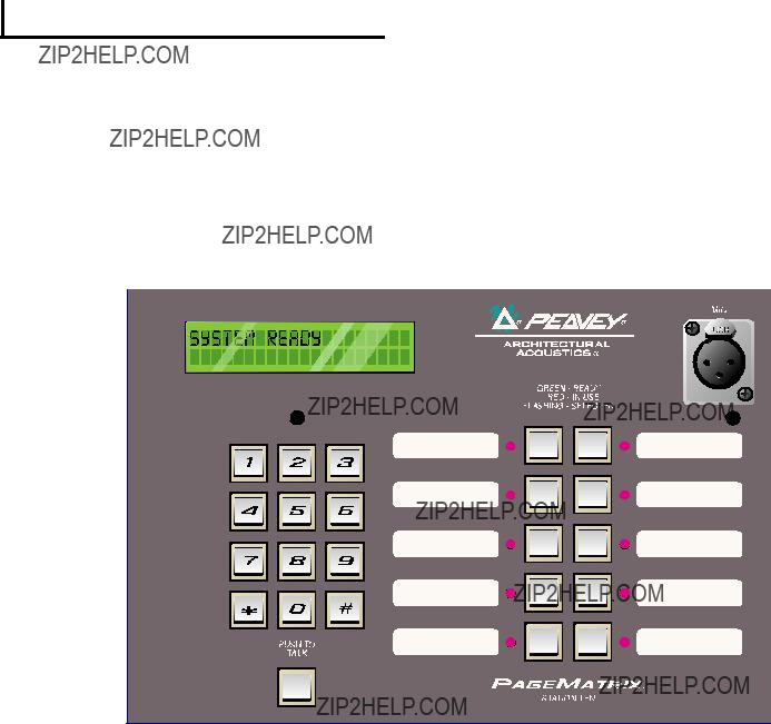
2.4.
Die Station Ten??? ist eine Tischstation mit zehn Tasten und einem
Frontplatte
Tastenaktivierung:
Zur Aktivierung des Mikrofons f??r die gew??hlte Voreinstellzone die Taste dr??cken.
10 Zonenvoreinstellungstasten mit Leuchtdioden:
Dienen zum Anw??hlen einer der zehn voreingestellten Zonen. Eine gr??ne Leuchtdiode zeigt an, da?? die betreffende Zone zug??nglich ist. Eine rote Leuchtdiode bedeutet, da?? die Zone gerade von einer anderen Station aus belegt wird. Zur Best??tigung der Wahl blinkt die Leuchtdiode.
Eingang f??r phantomgespeistes Mikrofon
Mic Volume (Lautst??rke):
Versenkte Mikrofonverst??rkungsjustierung
R??ckwand
F??nfpoliger Zusatzmikrofoneingang (Aux Mic)
Zum Anschlu?? eines separaten Mikrofons mit Tastenaktivierung. Siehe Schaltplan, Anhang 5.4. Das Zusatzmikrofon wird automatisch zur Voreinstellzone 1 gelenkt.
F??r den Anschlu?? am
82
Betrieb der Station Ten
???Die Leuchtdiodenfarbe gibt den Status der jeweiligen Voreinstellzone wieder:
???Gr??n bedeutet, da?? die Zone frei ist, d.h. nicht von einer anderen Station gerufen wird.
???Rot bedeutet, da?? die Zone belegt ist.
???Dr??ckt man auf die Sprechtaste, wird die gew??hlte Zonentaste orange und best??tigt damit die Aktivierung. Andere am System angeschlossene Stationen zeigen die entsprechende Zonentaste ROT an und signalisieren damit, da?? die Zone belegt ist.
???Zum W??hlen einer Zone dr??ckt man auf die entsprechende Taste. Zur Best??tigung der Wahl blinkt die Leuchtdiode.
???Beim Einschalten adressiert das Ger??t automatisch Zone 1.
???Der f??nfpolige Zusatzmikrofoneingang (Aux Mic) an der R??ckwand ist f??r Voreinstellzone 1 programmiert.
?????ber die Tastatur sind die Voreinstellzonen direkt zug??nglich. Man gibt einfach eine ein- oder zweistellige Zahl ein und dr??ckt dann auf die Taste ???#???.
???Der Name der angew??hlten Zone (er kann bis zu 16 Zeichen lang sein und wird vom Benutzer ??ber das
???Die obere Zeile des Displays gibt Namen und Status der Station an. Die zweite Zeile gibt den Namen der Zone an.
???Zum Beschriften der Voreinstellzonen sind wei??e Felder vorgesehen.
???Wenn alle Leuchtdioden beim Einschalten rot blinken, bedeutet dies, da?? die Station noch nicht programmiert ist.
???Wenn alle Leuchtdioden beim Einschalten gr??n blinken, bedeutet dies, da?? die Station programmiert ist.
???Beim Einschalten sowie nach einmin??tiger Inaktivit??t schaltet das Ger??t automatisch auf Zone 1 um.
Zonenvoreinstellungen
MediaMatrix definiert die Zonen, die einzelne Ausg??nge oder ganze Ausgangsgruppen umfassen k??nnen. Die
Bevorrechtigung
In PageMatrix gibt es keine systembedingten Bevorrechtigungen. Jedes Mikrofon kann jederzeit benutzt werden; die
83

2 . 4 . T y p i c a l P a g e M a t r i x C o n n e c t i o n
Up to 16 Stations of any combination
CAT 5 STANDARD ???Data Type??? cable is used.
However, there is voltage on the line. DO NOT
CONNECT to computer networks.
Station 4W???
CAT 5*
Cable
MediaMatrix??
Cable
BoB Cable
IA??? 200
CAT 5*
Cable
PageMatrix???
Audio
Cable
Lap Top
OR
MediaMatrix??
Com Port
84

3. Beschreibung der
3.1.
Mindestanforderungen:
3.2. Installieren der Software
Hinweis:
Die
1.
2.
3.
Schritt 1: Installieren der
A.Legen Sie Diskette 1 (PageMatrix Installation) in das Laufwerk ein.
B.F??hren Sie ???A:\setup.exe???aus.
C.Sie werden um Eingabe des Installationsverzeichnisses (C:\pagemtrx) sowie eines Programmgruppennamens (PageMatrix) gebeten. Die Dateien werden in dem gew??hlten Verzeichnis installiert, und die Programmgruppe wird erstellt. Wenn im Installationsfenster die Meldung ???Installation Complete!??? in roter Schrift erscheint, klicken Sie bitte auf die Schaltfl??che ???Finish??? oder ??? sofern diese Schaltfl??che fehlt ??? auf die Schaltfl??che ???Cancel???. Es ist nicht n??tig, den Computer nach der Installation neu zu starten.
Schritt 2: Installieren der
Hinweis: Bei der Installation der
A.Legen Sie Diskette 2 (MediaMatrix View Files) in das Laufwerk ein.
B.F??hren Sie ???A:\views.exe??? aus.
C.Dies ist eine selbstentpackende
D.Best??tigen Sie das Verzeichnis, und klicken Sie auf ???Unzip???.
E.Klicken Sie nach Abschlu?? der Installation auf ???Close???.
Schritt 3: Installieren der
A.Legen Sie Diskette 2 (MediaMatrix View Files) in das Laufwerk ein.
B.F??hren Sie ???A:\devices.exe??? aus.
C.Dies ist eine selbstentpackende
85
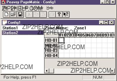
aufgefordert, in dem die entpackten Dateien abgelegt werden k??nnen. Diese Dateien M??SSEN im Verzeichnis ???Devices??? des
D.Best??tigen Sie das Verzeichnis, und klicken Sie auf ???Unzip???.
E.Klicken Sie nach Abschlu?? der Installation auf ???Close???.
3.2.1. Starten von PageMatrix
Windows 95:
1.W??hlen Sie im Men?? ???Start??? die Option ???Programme???.
2.Suchen und markieren Sie das
3.Suchen und markieren Sie PageMatrix.
Windows 3.1:
1.Suchen Sie im
2.Doppelklicken Sie auf die Gruppe, und doppelklicken Sie anschlie??end auf das
Hinweis: Bei Systemen, in denen PageMatrix nicht bereits geladen ist, kann das Programm mit dem
3.2.2. Stationen und Zonen
Das
Um einer Taste eine Zone zuzuweisen, markiert man die entsprechende Zone durch Anklicken mit der linken
Maustaste (daraufhin erscheint ein fetter Rahmen um die Zone) und klickt dann zur Best??tigung mit der rechten Maustaste (Zone wird rot).
Die Zonen stellen r??umliche Bereiche bzw. Ger??teausg??nge dar, die ??ber
Hinweis: Wird nur eine BoB verwendet, stehen maximal 8 Zonen zur Verf??gung.
Programmieren der Rufstationen mit dem
[Hinweis: Weitere Informationen siehe n??chstes Kapitel (Men??leiste).]
Mit der Option ???Insert Station??? bzw. ???Add Station??? (Men?? ???Edit???) k??nnen je nach Bedarf die vorhandenen Stationen programmiert werden. Nach dem Einrichten des
86

links auf dem Bildschirm eine Spalte zu sehen, in der alle angeschlossenen Rufstationen aufgelistet sind. Rechts oben befindet sich eine
und aktivieren Sie dann mit der Maus Zonen f??r jede Ruftaste. Wenn Sie fertig sind, laden Sie die Konfiguration in den
Benennen der Voreinstellzonen bei Verwendung der Station Ten
Station Ten hat ein 20 x 2 Zeichen gro??es Display, das die Zonenvoreinstellungen anzeigt. Die Benennung der Voreinstellzonen erfolgt ??ber PageMatrix. Wenn man dort eine Zehntastenstation einf??gt (Edit / Insert Station), erscheint am oberen Bildschirmrand die
3.3. Die Men??leiste des Programms ???PageMatrix???
3.3.1 Men?? ???File???
New (Neu)
W??hlt man ???New???, wird eine neue Konfiguration ge??ffnet, die auf den werkseingestellten Standardwerten beruht.
Open (??ffnen)
Ruft den
Close (Schlie??en)
Schlie??t die aktive Konfiguration.
Save (Speichern)
Speichert die aktuelle Konfiguration und alle daran vorgenommenen ??nderungen.
Save As (Speichern unter)
Ruft den
Print (Drucken)
Derzeit noch nicht benutzbar.
Print Preview (Seitenansicht)
Derzeit noch nicht benutzbar.
Print Setup??? (Druckereinrichtung)
Derzeit noch nicht benutzbar.
Download Configuration??? (Konfiguration fernladen)
Mit dieser Option werden die Konfigurationseinstellungen an den
Recent File List (Zuletzt ge??ffnete Dateien)
In diesem Bereich des Men??s werden die zuletzt bearbeiteten Konfigurationen aufgelistet. Sie k??nnen direkt von der Liste aus ge??ffnet werden.
Exit (Beenden)
Beendet PageMatrix.
87

3.3.2. Men?? ???Edit??? (Bearbeiten)
Undo (R??ckg??ngig)
Derzeit noch nicht benutzbar.
Cut (Ausschneiden)
Derzeit noch nicht benutzbar.
Copy (Kopieren)
Derzeit noch nicht benutzbar.
Paste (Einf??gen)
Derzeit noch nicht benutzbar.
Insert Station (Station einf??gen)
Dient zum Erstellen einer neuen Rufstation, die dann bearbeitet werden kann. Sie erscheint auf der Liste vor der derzeit gew??hlten Station. W??hlt man diese Option, erscheint das Dialogfeld ???New Station Properties???, das folgende Bearbeitungsvorg??nge erm??glicht:
Station Name: bis zu 16 Zeichen.
Number of buttons (Anzahl der Tasten): 4 oder 10.
PAC Port: Identifiziert den Anschlu??port
PAC Port Address (Adresse des
Add Station (Station hinzuf??gen)
Dient zum Erstellen einer neuen Rufstation, die dann bearbeitet werden kann. Sie erscheint am Ende der Liste. W??hlt man diese Option, erscheint das Dialogfeld ???New Station Properties???, das folgende Bearbeitungsvorg??nge erm??glicht:
Station Name: bis zu 16 Zeichen.
Number of buttons (Anzahl der Tasten): 4 oder 10.
PAC Port: Identifiziert den Anschlu??port
PAC Port Address (Adresse des
Delete Station (Station l??schen)
L??scht die markierte Station. Mit dem Dialogfeld ???Are You Sure???? (Sind Sie sicher?) werden Sie gebeten, den L??schvorgang zu best??tigen.
88

3.3.3. Men?? ???Tools/Options???
View Toolbar (Symbolleiste einblenden/ausblenden)
Bestimmt, ob die Symbolleiste angezeigt wird oder nicht.
View Status Bar (Statusleiste einblenden/ausblenden)
Bestimmt, ob die Statusleiste am unteren Rand des Fensters angezeigt wird oder nicht.
View Station Addresses (Stationsadressen anzeigen)
Vor jedem Stationsnamen wird die Stationsadresse angezeigt.
Max Number of Zones (max. Anzahl von Zonen)
Mit diesem Parameter wird die maximale Anzahl der Zonen in dem System festgelegt.
Communications (Kommunikation)
Dient zum Einstellen des Fernladeanschlusses. Zus??tzlich zu den
3.3.4. Men?? ???Window???
New Window (Neues Fenster)
??ffnet ein neues Fenster.
Cascade (??berlappen)
Standardfunktion von Windows, mit der alle ge??ffneten
Konfigurationen in gestaffelter Anordnung angezeigt werden.
Tile (Alle anordnen)
Standardfunktion von Windows, mit der alle ge??ffneten
Konfigurationen neben- und ??bereinander angeordnet werden.
Arrange Icons (Symbole anordnen)
Ordnet minimierte untergeordnete Fenster an.
Configuration Display (Konfigurationsanzeige)
Listet alle ge??ffneten Konfigurationen auf.
3.3.5. Men?? ???Hilfe???
About PageMatrix (Info zu PageMatrix)
Zeigt den Er??ffnungsbildschirm von PageMatrix an.
89

4.0.Das Funktionsschema von PageMatrix
4.1.??berblick
4.1.1. Die Komponenten
???Mindestens einer
???Dem
???Der
???Einem
???Einer Datei namens PASHA.ini, die f??r die Ansichtsdatei (View File) kompiliert ist.
4.1.2.Anschl??sse
Die Rufstationen werden mit
Die analogen Mikrofonsignale aller Rufstationen gelangen separat vom jeweiligen Ausgang an der R??ckwand des
Einer der seriellen Eing??nge an der R??ckwand des
4.1.3. Die
Das an der Rufstation angeschlossene tastenaktivierte Mikrofon wird lokal nicht beschaltet. Bei allen Modellen ist das Mikrofon immer eingeschaltet. Dr??ckt man eine Taste an der Station, wird lediglich die serielle Kommunikation mit dem Controller aktiviert.
4.1.4.Der
Diese Einheit hat drei Aufgaben:
1:Die Versorgung der Rufstationen mit Strom.
2:Die Weiterleitung der analogen Mikrofonsignale von den Rufstationen an die Eing??nge der ???BoB???s??? des
90
3:Die Interpretation der propriet??ren, von den Rufstationen gesendeten Steuerungsdaten und deren Umwandlung in serielle Standardstrings, die an MediaMatrix weitergeleitet werden k??nnen.
Der
4.1.4. Das
Neben vielen anderen Aufgaben ist das
4.1.5.Sprechtaste ??? Was geschieht?
1:Dr??ckt man auf eine Zonentaste an einer Station, werden die entsprechenden konfigurierten Zonen im MediaMatrix adressiert.
2:Bei Dr??cken der Sprechtaste sendet der
3:Dieser serielle Befehl wird durch MediaMatrix (??ber PASHA) interpretiert und ???bet??tigt??? die entsprechenden Leitschaltfl??chen in der
4:MediaMatrix leitet die Audiosignale an die Zone(n) weiter, solange die Sprechtaste an der Station gedr??ckt wird.
5:Funktionen wie Rufbevorrechtigung,
4.1.6.Der Betrieb von MediaMatrix
Rufanlagen sind komplizierte Systeme, die aus einer Vielzahl von Misch- und Leiteinheiten bestehen. So erfordert beispielsweise die Programmierung einer Rufeinheit aus 8 Stationen mit 32 Tasten, da?? eine
91
Inbetriebnahme ??? So wird???s gemacht???
1.Suchen Sie die
2.Benennen Sie diese Datei in ???pasha.ini??? um, und speichern Sie sie im Peavey- Verzeichnis ???mediamatrix\views???.
Hinweis: Wenn Sie die urspr??ngliche
3.??ffnen Sie MediaMatrix (sofern nicht bereits geschehen).
4.Um die verf??gbaren Einheiten einsehen zu k??nnen, w??hlen Sie im Men?? ???Device??? die Option ???Paging???.
5.W??hlen Sie eine vorhandene Einheit (device) aus, und stellen Sie die entsprechen- den Verbindungen her.
6.Testen Sie die Leitungsf??hrungen und Zonen.
Beispiel:
Angenommen, Sie m??chten die Datei ???1632.pav??? benutzen. Benennen Sie die Datei ???1632.txt??? in ???pasha.ini??? um. Legen Sie die neu erstellte Datei ???pasha.ini??? im
4.2. Fehlerbehebung 101
???Nicht vergessen ??? die Ansichtsdatei mu?? kompiliert werden.
???Vergewissern Sie sich, da?? Pasha.com (pasha.com1, pasha.com2, pasha.com3 oder pasha.com4) gestartet wird und dem f??r PageMatrix verwendeten
???Starten Sie PageMatrix, und programmieren Sie eine Testdatei.
???Pr??fen Sie in MediaMatrix anhand der visuellen Monitore der Ansichtsdatei, ob das System reagiert.
???Pr??fen Sie die Kabeltypen, alle Anschl??sse und die
92

5.Anhang
5.1.Werkseitiger Service
Peavey bietet direkten Werkskundendienst an. Sollten Sie weitere Hilfe oder zus??tzliche Informationen ben??tigen, rufen Sie uns bitte an. Sie erreichen uns von 8.00 bis 17.00 CST (= sieben Stunden fr??her als MEZ) unter 001 601 483 5376. Die Anschrift f??r alle Korrespondenzen sowie zum Anfordern von Lekt??re zu aktuellen und neuen Produkten lautet:
Peavey Electronics Corp. ??? MediaMatrix Support Group ??? 711 A St. ??? Meridian, MS 39301 ??? USA
Hilfreiche Tips, technische Daten, Antworten zu h??ufig gestellten Fragen (FAQ???s), Beispieldateien, Applikationsbrosch??ren und Informationen zu weiteren Produkten von Peavey Architectural Acoustics finden Sie rund um die Uhr auf unserer Site im World Wide Web. Die URL lautet:
http://www.peavey.com/division/arch/index.html
Um Ihnen im konkreten Fall den bestm??glichen technischen Service bieten zu k??nnen, m??ssen wir wahrscheinlich Ihre Ansichtsdatei durchsehen, um das Problem pr??zise diagnostizieren zu k??nnen. Dadurch wird Ihre Arbeit erleichtert und Ihr System effizienter. ??ber das Internet und per
George Douglas, National Sales Manager george@peavey.com
Ken Valentine, Central District Manager ken@peavey.com
Will Roland, Western District Manager will@peavey.com
Joel Moak, Southeastern District Manager joel@peavey.com
Levin Culpepper, Internal Tech Support Coordinator levin@peavey.com
Brent Harshbarger, Product Manager brent@peavey.com
In drigenden F??llen au??erhalb der normalen Gesch??ftszeiten k??nnen Sie unsere Mitarbeiter ??ber den
Bitte machen Sie von dieser M??glichkeit nur in wirklichen Notf??llen im
A R C H I T E C T U R A L A C O U S T I C S?? 711 A Street ??? Meridian, MS 39301
001 601 483 5376 ??? FAX 001 601 486 1678 http://www.peavey.com ??? ??1998
??nderungen an Ausstattung und technischen Daten vorbehalten.
93

5.2. Der MediaMatrix Program Launcher
Der Program Launcher (Programmstarter) ist im Men?? ???Device/Miscellaneous??? zu finden. Er erleichtert das ??ffnen anderer
94
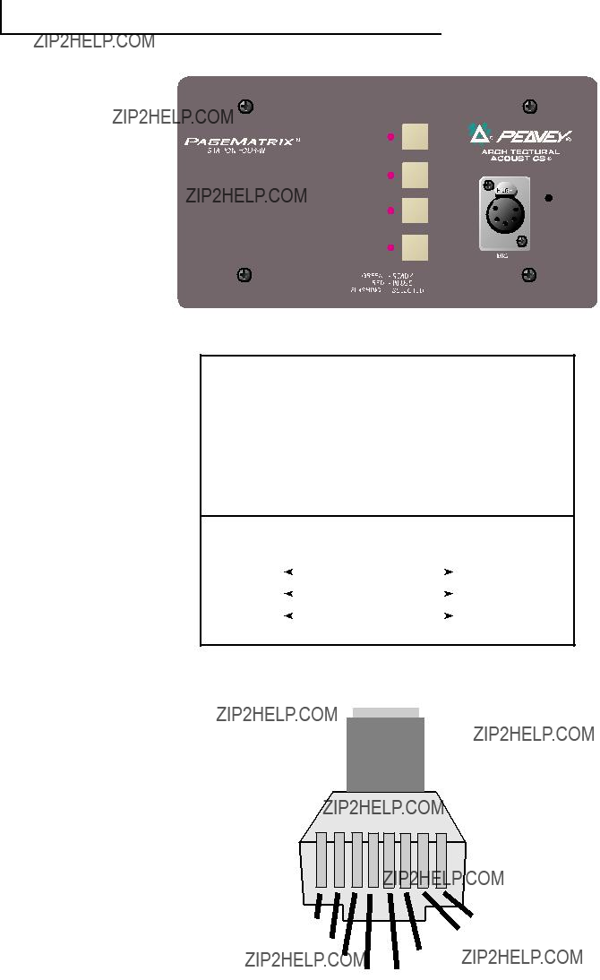
5 . 3 . S t a t i o n 4 - W W i r i n g D i a g r a m
1
 485+
485+
2 
 485 -
485 -
3 
 GND
GND
4 
 24V+
24V+
5 
 GND
GND
CAT 5
54
NOTE:
This is not a network connection.
95

5.4.
 Audio +
 Audio -
 Mic Switch
 GND
GND
96

5.5. Konfigurieren des
Wie bereits erw??hnt, unterst??tzt der
1.Obere Deckplatte des Controllers abnehmen (sechs Schrauben).
2.Im Inneren des Ger??ts befindet sich links vorne ein
3.Bitte stellen Sie nur die Schalter 1 und 2 um. Die nachstehende Tabelle zeigt Ihnen, wie.
4.Die Schalter 3 bis 8 sind inaktiv.
DIP SETTINGSCONTROLLER IDs
1 2 3 4 5 6 7 8
O
N
Stations 33 - 48
NOTE: Factory settings default to 1
97

5.6. Technische Daten
98
WICHTIGE SICHERHEITSRICHTLINIEN
WARNUNG: Beim Einsatz elektrischer Ger??te sollten stets nachfolgend genannte grundlegende Sicherheitsrichtlinien beachtet werden:
1.Lesen Sie diese Richtlinien.
2.Bewahren Sie diese Richtlinien stehts griffbereit auf.
3.Beachten Sie s??mtliche Richtlinien.
4.Befolgen Sie alle Anweisungen.
5.Benutzen Sie das Ger??t nicht in unmittelbarer Wassern??he (z. B. Badewanne, Waschbecken,
6.Nur mit einem feuchten oder klammen Tuch reinigen.
7.Keine der L??ftungsschlitze blockieren. F??hren Sie die Installation in ??bereinstimmung mit den Herstelleranweisungen durch. Nicht flach gegen eine Wand aufstellen oder in einem geschlossenen Geh??use unterbringen in dem die Frischluftzufuhr blockiert oder behindert wird.
8.Nicht in der N??he von Hitzequellen wie z. B. Radiatoren, Heizl??fter, ??fen oder sonstigen Apparaten (inkl. Verst??rker) aufstellen.
9.Beeintr??chtigen Sie nicht den Sicherheitszweck eines polarisierten oder
10.Sch??tzen Sie das Netzkabel vor mechanischen Einwirkungen, insbesondere am Stecker und Ger??teausla??.
11.Verwenden Sie nur vom Hersteller zur Verf??gung stehendes Bestigungsmaterial/Zubeh??r.
12.Nur in Verbindung mit einem vom Hersteller oder dem Apparat verkauften
13.Trennen Sie das Ger??t vom Stromnetz w??hrend eines Gewitters oder aber wenn es ??ber l??ngere Zeit unbenutzt bleibt.
14.??berlassen Sie s??mtliche Wartungsarbeiten qualifiziertem Fachpersonal. Wartungsarbeiten werden erforderlich, sobald das Ger??t in irgend einer Weise zu Schaden gekommen ist, wie wenn z.B. das Netzkabel besch??digt ist, Fl??ssigkeit ins Geh??use gelaufen ist, das Ger??t Regen oder Feuchtigkeit ausgesetzt wurde, keine normale Bedienung mehr m??glich ist oder das Ger??t gest??rtzt ist.
15.Bei der Rackmontage ist darauf zu achten, da?? die Ger??ter??ckseite gut zug??nglich bleibt.
16.Extrem hohe Lautst??rkepegel beeintr??chtigen das H??rverm??gen und k??nnen zum permanenten Verlust desselben f??hren. Die Anf??lligkeit variiert von Person zu Person. Unter den oben genanntenn Umst??nden und enstsprechender Zeit leidet jedoch ann??hernd jeder unter H??rverlust. Die Arbeitssicherheits- und Gesundheitsbeh??rde der
Gem???? OSHA, f??hrt jede exzessive Lautst??rkeaussetzung ??ber den erlaubten Grenzen bereits zu geringem H??rverlust.
Um dauerhafte Geh??rsch??den zu vermeiden, die durch ??ber dem erlaubten Pegel liegende exzessive Lautst??rken verursacht werden, m??ssen Ohrst??psel oder Ohrsch??tzer getragen werden. Um der Aussetzung potentiell gef??hrlicher Lautst??rkepegel aus dem Wege zu gehen wird emp- fohlen, da?? alle Personen die solchen Ger??ten ausgesetzt sind, die in der Lage sind solche hohen Lautst??rkepegel zu erzeugen (wie z.B. dieses Verst??rkersystem) sich durch Geh??rst??psel, Kapselgeh??rsch??tzer oder B??gelgeh??rsch??tzer zu sch??tzen.
BEWAHREN SIE DIESE RICHTLINIEN IMMER GRIFFBEREIT AUF!
99

NOTES:
100
NOTES:
101
IMPORTANT SAFETY INSTRUCTIONS
WARNING: When using electric products, basic cautions should always be followed, including the following:
1.Read these instructions.
2.Keep these instructions.
3.Heed all warnings.
4.Follow all instructions.
5.Do not use this apparatus near water. For example, near or in a bathtub, swimming pool, sink, wet basement, etc.
6.Clean only with a damp cloth.
7.Do not block any of the ventilation openings. Install in accordance with manufacturer???s instructions. It should not be placed flat against a wall or placed in a
8.Do not install near any heat sources such as radiators, heat registers, stoves or other apparatus (including amplifiers) that produce heat.
9.Do not defeat the safety purpose of the polarized or
10.Protect the power cord from being walked on or pinched particularly at plugs, convenience receptacles, and the point they exit from the apparatus.
11.Only use attachments/accessories provided by the manufacturer.
12.Use only with a cart, stand, tripod,bracket, or table specified by the manufacturer, or sold with the apparatus. When a cart is used, use caution when moving the cart/apparatus combination to avoid injury from
13.Unplug this apparatus during lightning storms or when unused for long periods of time.
14.Refer all servicing to qualified service personnel. Servicing is required when the apparatus has been damaged in any way, such as power- supply cord or plug is damaged, liquid has been spilled or objects have fallen into the apparatus, the apparatus has been exposed to rain or moisture, does not operate normally, or has been dropped..
15.If this product is to be mounted in an equipment rack, rear support should be provided.
16.Exposure to extremely high noise levels may cause a permanent hearing loss. Individuals vary considerably in susceptibility to noise induced hearing loss, but nearly everyone will lose some hearing if exposed to sufficiently intense noise for a sufficient time. The U.S. Government???s Occupational and Health Administration (OSHA) has specified the following permissible noise level exposures:.
According to OSHA, any exposure in excess of the above permissible limits could result in some hearing loss. Ear plugs or protectors to the ear canals or over the ears must be worn when operating this amplification system in order to prevent a permanent hearing loss if exposure is in excess of the limits as set forth above. To ensure against potentially dangerous exposure to high sound pressure levels, it is recommended that all persons exposed to equipment capable of producing high sound pressure levels such as this amplification system be protected by hearing protectors while this unit is in operation.
SAVE THESE INSTRUCTIONS!
102

PEAVEY ELECTRONICS CORPORATION LIMITED WARRANTY
Effective Date: July 1, 1998
What This Warranty Covers
Your Peavey Warranty covers defects in material and workmanship in Peavey products purchased and serviced in the U.S.A. and Canada.
What This Warranty Does Not Cover
The Warranty does not cover: (1) damage caused by accident, misuse, abuse, improper installation or operation, rental, product modification or neglect; (2) damage occurring during shipment; (3) damage caused by repair or service performed by persons not authorized by Peavey; (4) products on which the serial number has been altered, defaced or removed; (5) products not purchased from an Authorized Peavey Dealer.
Who This Warranty Protects
This Warranty protects only the original retail purchaser of the product.
How Long This Warranty Lasts
The Warranty begins on the date of purchase by the original retail purchaser. The duration of the Warranty is as follows:
[*denotes additional warranty period applicable if optional Warranty Registration Card is completed and returned to Peavey by original retail purchaser within 90 days of purchase.]
What Peavey Will Do
We will repair or replace (at Peavey's discretion) products covered by warranty at no charge for labor or materials. If the product or component must be shipped to Peavey for warranty service, the consumer must pay initial shipping charges. If the repairs are covered by warranty, Peavey will pay the return shipping charges.
How To Get Warranty Service
(1)Take the defective item and your sales receipt or other proof of date of purchase to your Authorized Peavey Dealer or Authorized Peavey Service Center.
OR
(2)Ship the defective item, prepaid, to Peavey Electronics Corporation, International Service Center, 412 Highway 11 & 80 East, Meridian, MS 39301 or Peavey Canada Ltd., 95 Shields Court, Markham, Ontario, Canada L3R 9T5. Include a detailed description of the problem, together with a copy of your sales receipt or other proof of date of purchase as evidence of warranty coverage. Also provide a complete return address.
Limitation of Implied Warranties
ANY IMPLIED WARRANTIES, INCLUDING WARRANTIES OF MERCHANTABILITY AND FITNESS FOR A PARTICULAR PURPOSE, ARE LIMITED
IN DURATION TO THE LENGTH OF THIS WARRANTY.
Some states do not allow limitations on how long an implied warranty lasts, so the above limitation may not apply to you.
Exclusions of Damages
PEAVEY'S LIABILITY FOR ANY DEFECTIVE PRODUCT IS LIMITED TO THE REPAIR OR REPLACEMENT OF THE PRODUCT, AT PEAVEY'S
OPTION. IF WE ELECT TO REPLACE THE PRODUCT, THE REPLACEMENT MAY BE A RECONDITIONED UNIT. PEAVEY SHALL NOT BE
LIABLE FOR DAMAGES BASED ON INCONVENIENCE, LOSS OF USE, LOST PROFITS, LOST SAVINGS, DAMAGE TO ANY OTHER EQUIP-
MENT OR OTHER ITEMS AT THE SITE OF USE, OR ANY OTHER DAMAGES WHETHER INCIDENTAL, CONSEQUENTIAL OR OTHERWISE,
EVEN IF PEAVEY HAS BEEN ADVISED OF THE POSSIBILITY OF SUCH DAMAGES
Some states do not allow the exclusion or limitation of incidental or consequential damages, so the above limitation or exclusion may not apply to you.
This Warranty gives you specific legal rights, and you may also have other rights which vary from state to state.
If you have any questions about this warranty or service received or if you need assistance in locating an Authorized Service Center, please contact the Peavey International Service Center at (601)
Features and specifications subject to change without notice.
103

Features and specifications subject to change without notice.
Peavey Electronics Corporations ??? 711 A Street ??? Meridian, MS 39301 ??? U.S.A. (601)