I C A ??? S E R I E S
I N D U S T R I A L C O N T R A C T O R A M P L I F I E R S
O P E R AT I N G G U I D E
I C A ??? S E R I E S
I N D U S T R I A L C O N T R A C T O R A M P L I F I E R S
O P E R AT I N G G U I D E

Intended to alert the user to the presence of uninsulated ???dangerous voltage??? within the product???s enclosure that may be of sufficient magnitude to constitute a risk of electric shock to persons.
Intended to alert the user of the presence of important operating and maintenance (servicing) instructions in the literature accompanying the product.
CAUTION: Risk of electrical shock ??? DO NOT OPEN!
CAUTION: To reduce the risk of electric shock, do not remove cover. No user serviceable parts inside. Refer servicing to qualified service personnel.
WARNING: To prevent electrical shock or fire hazard, do not expose this appliance to rain or moisture. Before using this appliance, read the operating guide for further warnings.
Este s??mbolo tiene el prop??sito, de alertar al usuario de la presencia de ???(voltaje) peligroso??? sin ais- lamiento dentro de la caja del producto y que puede tener una magnitud suficiente como para constituir riesgo de descarga el??ctrica.
Este s??mbolo tiene el prop??sito de alertar al usario de la presencia de instruccones importantes sobre la operaci??n y mantenimiento en la informaci??n que viene con el producto.
PRECAUCION: Riesgo de descarga el??ctrica ??NO ABRIR!
PRECAUCION: Para disminu??r el riesgo de descarga el??ctrica, no abra la cubierta. No hay piezas ??tiles dentro. Deje todo mantenimiento en manos del personal t??cnico cualificado.
ADVERTENCIA: Para evitar descargas el??ctricas o peligro de incendio, no deje expuesto a la lluvia o humedad este aparato Antes de usar este aparato, Iea m??s advertencias en la gu??a de operaci??n.
Ce symbole est utilis?? dans ce manuel pour indiquer ?? l???utilisateur la pr??sence d???une tension dangereuse pouvant ??tre d???amplitude suffisante pour constituer un risque de choc ??lectrique.
Ce symbole est utilis?? dans ce manuel pour indiquer ?? l???utilisateur qu???il ou qu???elle trouvera d???importantes instructions concernant l???utilisation et l???entretien de l???appareil dans le paragraphe signal??.
ATTENTION: Risques de choc ??lectrique ??? NE PAS OUVRIR!
ATTENTION: Afin de r??duire le risque de choc ??lectrique, ne pas enlever le couvercle. Il ne se trouve ?? l???int??rieur aucune pi??ce pouvant ??tre repar??e par l???utilisateur. Confiez I???entretien et la r??paration de l???appareil ?? un r??parateur Peavey agr????.
AVERTISSEMENT: Afin de pr??venir les risques de d??charge ??lectrique ou de feu, n???exposez pas cet appareil ?? la pluie ou ?? l???humidit??. Avant d???utiliser cet appareil, lisez attentivement les avertissements suppl??mentaires de ce manuel.
Dieses Symbol soll den Anwender vor unisolierten gef??hrlichen Spannungen innerhalb des Geh??uses warnen, die von Ausreichender St??rke sind, um einen elektrischen Schlag verursachen zu k??nnen.
Dieses Symbol soll den Benutzer auf wichtige Instruktionen in der Bedienungsanleitung aufmerksam machen, die Handhabung und Wartung des Produkts betreffen.
VORSICHT: Risiko ??? Elektrischer Schlag! Nicht ??ffnen!
VORSICHT: Um das Risiko eines elektrischen Schlages zu vermeiden, nicht die Abdeckung enfernen. Es befinden sich keine Teile darin, die vom Anwender repariert werden k??nnten. Reparaturen nur von qualifiziertem Fachpersonal durchf??hren lassen.
ACHTUNG: Um einen elektrischen Schlag oder Feuergefahr zu vermeiden, sollte dieses Ger??t nicht dem Regen oder Feuchtigkeit ausgesetzt werden. Vor Inbetriebnahme unbedingt die Bedienungsanleitung lesen.
2
TABLE OF CONTENTS
Page
INTRODUCTION . . . . . . . . . . . . . . . . . . . . . . . . . . . . . . . . . . . . . . . . . . . . . . . . . . . . 4 UNPACKING . . . . . . . . . . . . . . . . . . . . . . . . . . . . . . . . . . . . . . . . . . . . . . . . . . . . . . . 4 INSTALLATION AND MOUNTING . . . . . . . . . . . . . . . . . . . . . . . . . . . . . . . . . . . . . . . 4 BASIC SETUP. . . . . . . . . . . . . . . . . . . . . . . . . . . . . . . . . . . . . . . . . . . . . . . . . . . . . . 4 FRONT PANEL FEATURES. . . . . . . . . . . . . . . . . . . . . . . . . . . . . . . . . . . . . . . . . . . . 5 BACK PANEL FEATURES . . . . . . . . . . . . . . . . . . . . . . . . . . . . . . . . . . . . . . . . . . . . . 6 OPERATION . . . . . . . . . . . . . . . . . . . . . . . . . . . . . . . . . . . . . . . . . . . . . . . . . . . . . . . 7 PROTECTION FEATURES . . . . . . . . . . . . . . . . . . . . . . . . . . . . . . . . . . . . . . . . . . . . 9 SEQUENTIAL
3

ENGLISH
INTRODUCTION
Congratulations on your purchase of an Architectural Acoustics ICA??? (Industrial Contractor Amplifier) from Peavey Electronics. Please read this manual carefully, especially the IMPORTANT SAFETY INSTRUCTIONS on page 18. It contains information vital to safe operation of the power amplifier. Also, please fill out and return the enclosed product registration card.
ICA Series amplifiers represent new levels of value and flexibility never before offered to the contracting market. The ICA Series features models specifically designed to drive
ICA Series amplifiers are ruggedly built from
If you need setup or operational assistance for this product, please call the Peavey Electronics Customer Service Department or your local Peavey Electronics representative. We appreciate suggestions that may help us improve our products and/or service.
UNPACKING
Inspect the amplifier during unpacking. If you find any damage, notify your dealer immediately. Only the consignee may institute a claim with the carrier for damage incurred during shipping. Be sure to save the carton and all packing materials. Should you ever need to ship the unit back to Peavey Electronics, one of its service centers, or the dealer; use only the original factory packing.
INSTALLATION AND MOUNTING
ICA Series amplifiers are 2 or
BASIC SETUP
1.Rack mount the amplifier in the location where it is to be used, remembering to allow for adequate access and cooling space. For more information, see the sections on INSTALLATION AND MOUNTING and COOLING REQUIREMENTS.
2.Make input connections to the plugable terminal blocks on the rear panel. Use the proper connections for stereo, parallel, bridged mono, and grounding configuration. See the sections on SIGNAL MODE CONFIGURATION and INPUT MODULE CONNECTIONS for more information.
3.Connect speakers to the output barrier strip. Be sure to make the correct output connections for stereo, parallel or bridged mono configuration. See the section on SPEAKER OUTPUT CONNECTIONS for more information.
4.Make power connections, allowing for proper current draw. See the sections on IEC POWER CONNECTOR and AC MAINS CIRCUIT SIZE REQUIREMENTS for more information.
5.Turn the front panel
4

FRONT PANEL FEATURES
TM
600
RCHITECTURAL
POWER
A 


1.RACK MOUNTING EARS
These mounting holes are provided on each front mounting ear.
2.
A
3.POWER LED
The POWER LED illuminates when the amplifier is turned on.
4.SIGNAL LED
Each channel has a SIGNAL LED that illuminates when the amplifier output exceeds 1 volt.
5.CLIP LED
Each channel has a CLIP LED that illuminates at the clipping point, and indicates that internal circuitry is reducing amplifier gain to allow full power. See the section on PROTECTION FEATURES for more information.
6.LFC??? LED
Each channel has a LFC (Load Fault Correction) LED. This LED illuminates when the amplifier channel detects an abnormal load condition. Internal circuitry will instantaneously reduce the channel gain to allow the amplifier to operate at a safe level into the abnormal load. See the section on PROTECTION FEATURES for more information.
7.PROTECT LED
If the amplifier has just been turned on or has detected a fault condition, the speaker output relays will open, illuminating this LED.
5

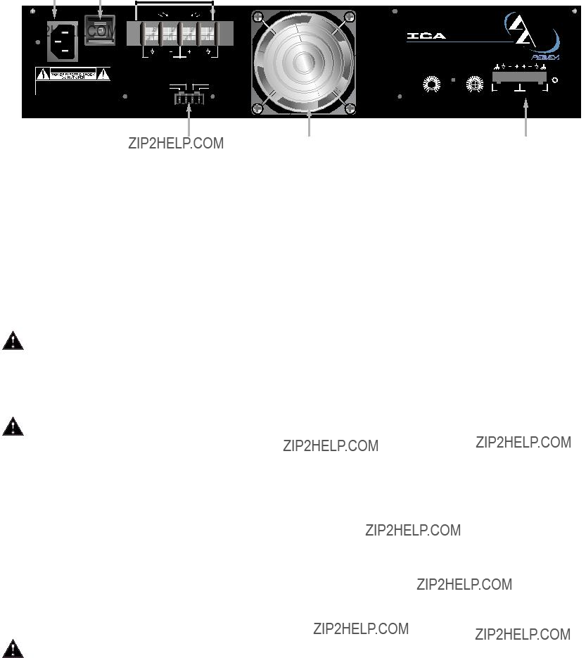
BACK PANEL FEATURES
8.INPUT SECTION
The ICA??? Series comes standard with plugable input connectors and individual channel rotary attenuators. Connections at the input connector permit the audio signal ground to be connected or lifted from the chassis ground.
9.OUTPUT BARRIER STRIP
A barrier strip is provided for connection of loudspeakers with bare wire or spade lug connectors. This barrier strip can accommodate up to two
10.IEC POWER CONNECTOR
A standard IEC power connector is located at the upper left corner of the amplifier rear panel.
An AC mains cord having an appropriate AC plug for the intended operating voltage is included.
NOTE: FOR UK ONLY
If the colors of the wires in the mains lead of this unit do not correspond with the colored markings identifying the terminals in your plug, proceed as follows: (1) The wire that is colored green and yellow must be connected to the terminal that is marked by the letter E, the earth symbol, colored green, or colored green and yellow. (2) The wire that is colored blue must be connected to the terminal that is marked with the letter N or the color black. (3). The wire that is colored brown must be connected to the terminal that is marked with the letter L or the color red.
11.CIRCUIT BREAKER
A resettable, protective AC circuit breaker is located at the upper left of the amplifier back
panel. If the breaker has tripped, push it back in to return the amplifier to operating condition. If the breaker continues to trip, the amplifier needs servicing. Do not continue to reset the breaker because severe internal damage and safety hazards could occur!
12.SEQUENTIAL
The ICA??? Series comes standard with
6

connecting the ENABLE OUT to the ENABLE IN of the next amplifier. A mating connector is shipped with the amplifier.
13.FAN GRILL
A continuously
intake! The fan operates only when the amplifier heat sinks require cooling.
OPERATION
AC MAINS CIRCUIT SIZE REQUIREMENTS
Power requirements for ICA??? amplifiers are rated at ???idle???, 1/8 power (???typical??? music conditions), 1/3 power, and maximum rated power. The maximum power current draw rating
is limited by the amplifier???s circuit breaker. Consult the specification sheet for the current that each amplifier will demand. AC mains voltage must be the same as that indicated on the back of the amplifier. Damage caused by connecting the amplifier to improper AC voltage is not covered by any warranty. NOTE: Always turn off and disconnect the amplifier from the mains voltage before making audio connections. As an extra precaution, have the input attenuators turned down during initial power up.
COOLING REQUIREMENTS
ICA Series amplifiers use a
panel, and exhausts through slots on the front panel. The fan will remain inactive until internal operating temperature rises above 45?? C (113?? F). Make sure there is enough space around the back of the amplifier to allow air to enter. NOTE: If the amplifier is rack mounted, do not use doors or covers on the front or back without pressurizing the back of the rack. Whatever type of rack you are using, make sure that heated air can escape freely, and that there is no resistance to the intake of cool air through the back grill. Intake and exhaust air must flow without resistance.
HIBERNATION???
All ICA Series amps feature Hibernation circuitry. Current draw and thermal emissions are at a minimum when the absence of input signal is sensed for more than a minute. Once signal is present, Hibernation instantly restores the amplifier to normal. Current draw specifications while Hibernation is active are included in specifications under Idle Current Draw.
THERMAL EMISSIONS
The system installer or designer should specify system cooling needs. Refer to the specifications at the back of this manual for specific thermal emissions figures.
INPUT CONNECTIONS
The input connector accepts balanced and unbalanced audio signals. For use with an unbalanced source, tie the inverting
7

SIGNAL MODE CONFIGURATION
ICA??? Series amplifiers are configured for Stereo
To send the same signal to both channels (Parallel Mode), connect the input signal to CHANNEL A via the input connector. Run jumpers from the positive and negative terminals of the CHANNEL A input connector to the respective terminals of CHANNEL B. Both channels then share the CHANNEL A input signal but will operate independently. Speakers are connected as in Stereo Mode.
Bridged Mode converts the amplifier into a
STEREO MODE CONNECTION DIAGRAM
PARALLEL MODE DIAGRAM

BRIDGED MODE DIAGRAM
SPEAKER OUTPUT CONNECTIONS
Speakers are connected using the output barrier strip connectors. Spade lugs, ring tongues or bare wire may be connected to the output barrier strip elements. The barrier strip can accommodate up to two
SIGNAL GROUND CONNECTION
Connections at the input connector permit the audio signal ground to be connected or lifted from the chassis ground. When possible, the shield of the signal source connecting cable should connect to the chassis ground. In some cases, however, particularly if an amplifier is being installed in an existing system, this may result in a ground loop. If this happens, connect the shield to the signal ground only. The chassis ground also connects to the AC ground internally. If the cable shield is connected to the signal ground only, it will be clamped to +/- 0.6 V above or below chassis/AC ground.
PROTECTION FEATURES
The ICA??? Series incorporates protection features derived from Peavey???s extensive experience with reliability. The amplifiers are ruggedly built from
CLIP LIMITING
At the amplifier???s full power, or clipping point, the channel gain will automatically be reduced, guarding the loudspeakers against damaging high power and continuous square waves that would otherwise be produced. This is indicated by illumination of the CLIP LED. Normal program transients will not trigger Clip Limiting, only steady or excessive clipping will. Operation is virtually transparent in use and full signal bandwidth is maintained.
LOAD FAULT CORRECTION???
LFC is an innovative circuit that will instantaneously reduce channel gain to allow the amplifier to operate at a safe level into an abnormal load. LFC activation is indicated by illumination of the LFC LED. Moderate activation of LFC is inaudible in normal use. In addition, if extreme low impedance or a short circuit is encountered during high signal level conditions, the amplifier???s output relay will open.
9

This feature operates every time the amplifier is turned on, or after a protect condition. During turn on, the amplifier goes into protect mode and leaves the speaker load disconnected until the amplifier determines that the operating status is normal. The
THERMAL PROTECTION
If the heatsink or power transformer reaches an abnormally high temperature, the amplifier will protect itself by disconnecting the speaker load until the amplifier returns to a normal temperature. During this time, the PROTECT LED will illuminate, and the cooling fan will operate at maximum speed.
SHORT CIRCUIT
If an output is shorted, the LFC???, speaker relay and thermal circuits will automatically protect the amplifier. The LFC circuit senses the short circuit as an abnormal load condition and reduces the channel gain to a safe level for the load. In extreme or severe conditions, the speaker relays will disconnect the load and initiate a
DC VOLTAGE PROTECTION
If an amplifier channel detects DC voltage or subsonic signals at its output terminals, the speaker relay will immediately open to prevent loudspeaker damage. The PROTECT LED will illuminate as notification of this condition.
SEQUENTIAL
The ICA??? Series comes standard with remote sequential
Sequential
10
WIRE GAUGE CHART
______________________________________________________
11
ICA??? 600 SPECIFICATIONS
Due to our efforts for constant improvements, features and specifications are subject to change without notice.
12
ICA??? 1200 SPECIFICATIONS
Rated Power (2 X 4 ohms):
600 watts @ 20 Hz - 20 kHz, both channels driven at < 0.1% THD
Rated Power (2 X 8 ohms):
400 watts @ 20 Hz - 20 kHz, both channels driven at < 0.05% THD
Rated Power (1 X 4 ohms):
700 watts @ 1 kHz at < 0.008% THD
Rated Power (1 X 8 ohms):
425 watts @ 1 kHz at < 0.005% THD
Minimum Load Impedance:
4 ohms
Maximum RMS Voltage Swing:
70 volts
Frequency Response:
10 Hz - 25 kHz; +0,
Power Bandwidth:
10 Hz - 100 kHz; +0,
THD (2 x 4 ohms):
<0.1% @ 600 W from 20 Hz - 20 kHz with both channels driven
THD (2 x 8 ohms):
<0.05% @ 400 W from 20 Hz - 20 kHz with both channels driven
THD (1 X 4 ohms):
<0.008% @ 700 W @ 1 kHz
THD (1 X 8 ohms):
<0.005% @ 425 W @ 1 kHz
SMPTE IMD:
<0.1% 60 Hz and 7 kHz, 600 W @ 4 ohms
Slew Rate:
30 V/??s
Damping Factor (8 ohms):
>350:1 @ 20 Hz - 1 kHz
Input CMRR:
Voltage Gain:
x40 (32 dB)
Input Sensitivity:
1.22 volts @ 4 ohms, 1.41 volts @
8 ohms
Input Impedance:
20 k ohms, balanced
Hum and Noise:
Crosstalk:
Current Draw @ 1/8 power:
950 watts @ 4 ohms, 725 watts @
8 ohms
Current Draw @ 1/3 power:
1,750 watts @ 4 ohms, 1,150 watts @ 8 ohms
Idle Current Draw:
32 watts in Standby Mode
Maximum Current Draw:
2,670 watts @ 4 ohms (time limited by breaker), 1,725 watts @ 8 ohms
Thermal Emissions (BTU/hr.):
1,100 @ 1/3 power 4 ohms,
850 @ 1/3 power 8 ohms,
635 @ 1/8 power 4 ohms,
540 @ 1/8 power 8 ohms
Cooling
120 mm DC fan, off until heatsinks reach 45?? C, then variable speed
Controls:
2 rear panel attenuators, sequential
Indicator LEDs:
2 Clip, 2 Signal, 2 LFC, 1 Protect,
1 Power
Protection:
Temp., DC,
Connectors:
Construction:
All steel; 16 ga. chassis, 18 ga. top, 12 ga. rack ears
Dimensions:
5.25" x 19" x 16.4"
133 mm x 483 mm x 416.6 mm
Gross Weight:
51.4 lbs. (23.3 kg)
Net Weight:
45 lbs. (20.4 kg)
Due to our efforts for constant improvements, features and specifications are subject to change without notice.
13
ICA??? 2400 SPECIFICATIONS
Rated Power (2 x 4 ohms):
1200 watts @ 20 Hz - 20 kHz both channels driven at < 0.1% THD
Rated Power (2 x 8 ohms):
800 watts @ 20 Hz ??? 20 kHz both channels driven at < 0.08% THD
Rated Power (1 x 4 ohms):
1325 watts @ 1 kHz at < 0.08% THD
Rated Power (1 x 8 ohms):
830 watts @ 1 kHz at < 0.08% THD
Topology:
Class H
Minimum Load Impedance:
4 ohms
Maximum RMS Voltage Swing:
95 volts
Frequency Response:
10 Hz ??? 25 kHz; +0,
Power Bandwidth:
10 Hz ??? 50 kHz; +0,
THD (2 x 4 ohms):
<0.025% @ 1200 W @ 1 kHz with both channels driven
THD (2 x 8 ohms):
<0.008% @ 800 W @ 1 kHz with both channels driven
THD (1 x 4 ohms):
<0.015% @ 1325 W @ 1kHz
THD (1 x 8 ohms):
<0.006% @ 830 W @ 1kHz
SMPTE IMD:
<0.1% 60 Hz and 7 kHz, 800 W @ 8 ohms
Slew Rate:
35 V/us
Damping Factor (8 ohms):
>250:1 @ 20 Hz ??? 1 kHz
Input CMRR:
> 65 dB @ 1 kHz
Voltage Gain:
x 40 (32 dB)
Input Sensitivity:
1.73 volts @ 4 ohms, 2 volts @
8 ohms
Input Impedance:
20 k ohms, balanced
Hum and Noise:
Crosstalk:
Current Draw @ 1/8 power:
575 watts @ 4 ohms, 380 watts @
8 ohms
Current Draw @ 1/3 power:
1185 watts @ 4 ohms, 860 watts @
8 ohms
Idle Current Draw:
35 VA in Standby Mode
Maximum Current Draw:
2,760 VA (time limited by breaker)
Thermal Emissions (BTU/hr.):
940 @ 1/8 power 4 ohms,
615 @ 1/8 power 8 ohms,
1830 @ 1/3 power 4 ohms,
1335 @ 1/3 power @ 8 ohms
Cooling:
120 mm DC fan, off until heatsinks reach 45?? C, then variable speed
Controls:
2 rear panel attenuators, sequential
Indicator LEDs:
2 Clip, 2 Signal, 2 LFC, 1 Protect,
1 Power
Protection:
Temp., DC,
Connectors:
Construction:
All steel; 16 ga. chassis, 18 ga. top, 12 ga. rack ears
Dimensions:
5.25" x 19" x 16.4"
133 mm x 483 mm x 416.6 mm,
Gross Weight:
51.4 lbs. (23.3 kg.)
Net Weight:
45 lbs. (20.4 kg.)
Due to our efforts for constant improvements, features and specifications are subject to change without notice.
14
ICA??? 400V SPECIFICATIONS
Rated Power (two channels):
200 watts @ 20 Hz - 20 kHz both channels driven at <0.1% THD
Rated Power (one channel):
215 watts @ 1 kHz at <0.0075%
THD
Minimum Load Impedance:
ICA
ICA
Maximum RMS Voltage Swing:
ICA
ICA
Frequency Response:
10 Hz - 25 kHz; +0,
Power Bandwidth:
ICA
10 Hz - 100 kHz; +0,
ICA
10 Hz - 50 kHz; +0,
THD (two channels driven):
ICA
<0.1% @ 200 W from 20 Hz - 20 kHz with both channels driven
ICA
<0.15% @ 200 W from 20 Hz - 20 kHz with both channels driven
THD (one channel driven):
ICA
<0.005% @ 200 W @ 1 kHz
ICA
<0.015% @ 200 W @ 1 kHz
SMPTE IMD:
<0.1% 60 Hz and 7 kHz, 200 W
Slew Rate:
ICA
ICA
Damping Factor:
ICA
>1,000:1 @ 20 Hz - 400 Hz
ICA
>2,000:1 @ 20 Hz - 400 Hz
Input CMRR:
>
Voltage Gain:
x40 (32 dB)
Input Sensitivity:
ICA
1.77 volts for rated output ICA
2.5 volts for rated output
Input Impedance:
20 k ohms, balanced
Hum and Noise:
>
Crosstalk:
ICA
ICA
Current Draw @ 1/8 power:
ICA
ICA
Current Draw @ 1/3 power:
ICA
ICA
Idle Current Draw:
ICA
38 watts in Standby Mode ICA
43 watts in Standby Mode
Maximum Current Draw:
ICA
970 watts for rated power ICA
840 watts for rated power
Thermal Emissions (BTU/hr.):
500 @ 1/3 power,
350 @ 1/8 power
Cooling:
80 mm DC fan, off until heatsinks reach 45o C, then variable speed
Controls:
2 rear panel attenuators, sequential
Indicator LEDs:
2 Clip, 2 Signal, 2 LFC, 1 Protect,
1 Power
Protection:
Temp., DC,
Connectors:
Construction:
All steel; 16 ga. chassis, 18 ga. top, 12 ga. rack ears
Dimensions:
3.48" x 19" x 16.4"
88.4 mm x 483 mm x 416.6 mm
Gross Weight:
33.5 lbs. (15.2 kg.)
Net Weight:
31 lbs. (14 kg.)
Due to our efforts for constant improvements, features and specifications are subject to change without notice.
15
ICA??? 800V SPECIFICATIONS
Rated Power (two channels):
400 watts @ 20 Hz - 20 kHz both channels driven at < 0.1% THD
Rated Power (one channel):
415 watts @ 1 kHz at < 0.01% THD
Minimum Load Impedance:
ICA
ICA
Maximum RMS Voltage Swing:
ICA
ICA
Frequency Response:
10 Hz - 25 kHz; +0,
Power Bandwidth:
ICA
10 Hz - 100 kHz; +0,
ICA
10 Hz - 50 kHz; +0,
THD (two channels driven):
ICA
<0.15% @ 400 W from 20 Hz - 20 kHz with both channels driven ICA
<0.1% @ 400 W from 20 Hz - 20 kHz with both channels driven
THD (one channel driven):
<0.008% @ 400 W @ 1 kHz
SMPTE IMD:
<0.1% 60 Hz and 7 kHz, @ 400 W
Slew Rate:
35 V/??s
Damping Factor:
>400:1 @ 20 Hz - 400 Hz
Input CMRR:
Voltage Gain:
x40 (32 dB)
Input Sensitivity:
ICA
1.77 volts for rated output ICA
2.5 volts for rated output
Input Impedance:
20 k ohms, balanced
Hum and Noise:
>
Crosstalk:
>
Current Draw @ 1/8 power:
ICA
ICA
Current Draw @ 1/3 power:
ICA
ICA
Idle Current Draw:
45 watts in Standby Mode
Maximum Current Draw:
ICA
1,680 watts for rated power ICA
1,700 watts for rated power
Thermal Emissions (BTU/hr.):
550 @ 1/8 power,
835 @ 1/3 power
Cooling:
120 mm DC fan, off until heatsinks reach 45o C, then variable speed
Controls:
2 rear panel attenuators, sequential
Indicator LEDs:
2 Clip, 2 Signal, 2 LFC, 1 Protect,
1 Power
Protection:
Temp., DC,
Connectors:
Construction:
All steel; 16 ga. chassis, 18 ga. top, 12 ga. rack ears
Dimensions:
5.25" x 19" x 16.4"
133 mm x 483 mm x 416.6 mm
Gross Weight:
51.4 lbs. (23.3 kg.)
Net Weight:
45 lbs. (20.4 kg.)
Due to our efforts for constant improvements, features and specifications are subject to change without notice.
16
ICA??? 2400V SPECIFICATIONS
Rated Power (2 x 4 ohms):
1200 watts @ 20 Hz - 20 kHz both channels driven at < 0.1% THD
Rated Power (2 x 8 ohms):
800 watts @ 20 Hz ??? 20 kHz both channels driven at < 0.08% THD
Rated Power (1 x 4 ohms):
1325 watts @ 1 kHz at < 0.08% THD
Rated Power (1 x 8 ohms):
830 watts @ 1 kHz at < 0.08% THD
Topology:
Class H
Minimum Load Impedance:
4 ohms
Maximum RMS Voltage Swing:
95 volts
Frequency Response:
10 Hz ??? 25 kHz; +0,
Power Bandwidth:
10 Hz ??? 50 kHz; +0,
THD (2 x 4 ohms):
<0.025% @ 1200 W @ 1 kHz with both channels driven
THD (2 x 8 ohms):
<0.008% @ 800 W @ 1 kHz with both channels driven
THD (1 x 4 ohms):
<0.015% @ 1325 W @ 1kHz
THD (1 x 8 ohms):
<0.006% @ 830 W @ 1kHz
SMPTE IMD:
<0.1% 60 Hz and 7 kHz, 800 W @ 8 ohms
Slew Rate:
35 V/us
Damping Factor (8 ohms):
>250:1 @ 20 Hz ??? 1 kHz
Input CMRR:
> 65 dB @ 1 kHz
Voltage Gain:
x 40 (32 dB)
Input Sensitivity:
1.73 volts @ 4 ohms, 2 volts @
8 ohms
Input Impedance:
20 k ohms, balanced
Hum and Noise:
Crosstalk:
Current Draw @ 1/8 power:
575 watts @ 4 ohms, 380 watts @
8 ohms
Current Draw @ 1/3 power:
1185 watts @ 4 ohms, 860 watts @
8 ohms
Idle Current Draw:
35 VA in Standby Mode
Maximum Current Draw:
2,760 VA (time limited by breaker)
Thermal Emissions (BTU/hr.):
940 @ 1/8 power 4 ohms,
615 @ 1/8 power 8 ohms,
1830 @ 1/3 power 4 ohms,
1335 @ 1/3 power @ 8 ohms
Cooling:
120 mm DC fan, off until heatsinks reach 45?? C, then variable speed
Controls:
2 rear panel attenuators, sequential
Indicator LEDs:
2 Clip, 2 Signal, 2 LFC, 1 Protect,
1 Power
Protection:
Temp., DC,
Connectors:
Construction:
All steel; 16 ga. chassis, 18 ga. top, 12 ga. rack ears
Dimensions:
5.25" x 19" x 16.4"
133 mm x 483 mm x 416.6 mm,
Gross Weight:
51.4 lbs. (23.3 kg.)
Net Weight:
45 lbs. (20.4 kg.)
Due to our efforts for constant improvements, features and specifications are subject to change without notice.
17

ESPA??OL
INTRODUCCI??N
Felicidades en su compra de un amplificador de Ac??stica Arquitect??nica ICA??? (Amplificador de Contratistas Ac??sticos por sus siglas en Ingl??s) de Peavey Electronics. Por favor lea este manual con atenci??n, especialmente la seccione de SEGURIDAD en la p??gina 18. Esta contiene informaci??n vital para la operaci??n segura del amplificador. Por favor t??mese el tiempo de llenar y mandar su tarjeta de registro del producto.
La serie de amplificadores ICA presenta nuevos niveles de valor y flexibilidad nunca antes ofrecidos en el mercado de contratistas. La serie ICA incluye modelos espec??ficamente dise??ados para alimentar salidas de 4 ohmios, salidas de 70.7 voltios y salidas de 100 voltios. Las salidas de 70.7 voltios y 100 voltios pueden ser alimentadas directamente, eliminando la necesidad de transformadores. Estos amplificadores cubren casi todas las necesidades de distribuci??n o instalaci??n de poder de sonido imaginables.
Los amplificadores de la serie ICA han sido construidos para que sean durables con materiales de alta calidad para proporcionar la protecci??n requerida a los circuitos y proteger al amplificador de situaciones ???de la vida real???.
Si requiere informaci??n adicional o asistencia en la operaci??n de este producto, por favor llame al Departamento de Servicio al Cliente de Peavey Electronics o su representante de Peavey local. Las sugerencias que nos ayuden a mejorar nuestros productos siempre son bienvenidas.
DESEMPACAR
Por favor inspeccione el amplificador cuando lo desempaque. Si encuentra alg??n da??o, inform?? a su distribuidor inmediatamente. S??lo el consignatario puede llevar a cabo un reclamo con el transportista en caso que se hayan experimentado da??os durante el flete. Aseg??rese de guardar la caja y todos los materiales de empaque. Si alguna vez fuera necesario enviar el producto Peavey Electronics o alguno de sus centros de servicio, o distribuidores, use s??lo los materiales de empaque originales.
INSTALACI??N Y MONTURA
Los amplificadores de la serie ICA son unidades de 2 ?? 3 espacios de rack con 15 3/4" (400 mm) de profundidad que se pueden montar en un rack est??ndar de 19". En todos los amplificadores se proporcionan agujeros al frente para montar la unidad.
INSTALACI??N B??SICA
1.Acomode el amplificador en el espacio de rack donde lo quiera instalar, asegur??ndose de mantener suficiente espacio de acceso, as?? como de ventilaci??n de enfriamiento. Para m??s informaci??n, ver las secciones de Instalaci??n y Montura y Requisitos de Enfriamiento.
2.Lleve a cabo las conexiones de entrada necesarias en los bloques de terminales del panel trasero. Use las conexiones apropiadas para funcionamiento est??reo, paralelo, mono (en puente), y configuraci??n de tierra. Vea la secci??n de Configuraci??n de Modos de Se??al y M??dulo de Conexiones de Entrada para m??s informaci??n.
3.Conecte las bocinas o altavoces al m??dulo de salida. Aseg??rese de llevar a cabo las conexiones correctas para est??reo, paralelo o mono/puente. Vea la secci??n Conectores de Salida de Bocinas para m??s informaci??n.
18

4.Lleve a cabo las conexiones de poder, cubriendo las necesidades del amplificador. Vea las secciones CONECTOR IEC y Requisitos de los circuitos de CA para m??s informaci??n.
5.Gire el interruptor de poder (AC POWER) de tres posiciones a la posici??n ON y suba los atenuadores de ganancia (LEVEL) en el panel trasero a los niveles deseados.
CARACTER??STICAS DEL PANEL FRONTAL
TM
600
RCHITECTURAL
POWER
A 


1.INSTALADOR PARA RACK
Estos agujeros se proporcionan en todas las unidades para su instalaci??n.
2.INTERRUPTOR DE PODER (AC POWER) DE TRES POSICIONES
Un interruptor de poder de tres posiciones se encuentra en el panel frontal. La capacidad de encender secuencialmente de forma remota es est??ndar. Con el interruptor presionado hacia la posici??n de afuera, el amplificador est?? encendido. La posici??n del medio es apagado y la posici??n adentro es STANDBY. Cuando se selecciona STANDBY el amplificador puede ser activado por circuitos de encendido secuenciales. Vea la secci??n Encendido/Apagado secuencial para m??s informaci??n.
3.LED DE PODER
El LED de poder se enciende cuando el amplificador est?? encendido.
4.LED DE SE??AL
Cada canal cuenta con un LED de se??al que se ilumina cuando el amplificador excede 1 voltio.
5.LED DE CLIP
Cada canal cuenta con un LED de clip que se ilumina en el punto de saturaci??n, e indica que los circuitos internos est??n reduciendo la ganancia del amplificador para permitir el uso de todo el poder. Vea la secci??n sobre Protecci??n para m??s informaci??n.
6.LFC??? LED
Cada canal cuenta con un LED de LFC (Correcci??n de Carga Fallida, por sus siglas en Ingl??s). Este LED se enciende cuando el canal del amplificador detecta una carga de condiciones anormales. Los circuitos internos instant??neamente reducen la ganancia del canal para permitir que el amplificador opere a un nivel seguro a pesar de la carga anormal. Vea la secci??n sobre Protecci??n para m??s informaci??n.
7.LED DE PROTECCI??N
Si el amplificador acaba de ser encendido o ha detectado una condici??n fallida, los relays de salida se abrir??n, iluminando este LED.
19

CARACTER??STICAS DEL PANEL TRASERO
8.SECCI??N DE ENTRADA
La serie ICA cuenta con conectores de entrada y atenuadores rotativos individuales para cada canal como equipamiento est??ndar. Las conexiones en los conectores de entrada permiten que la tierra de la se??al de audio sea conectada o levantada de la tierra del chasis.
9.CONECTORES DE SALIDA DE PARA CABLES
Se ha proporcionado una secci??n a la que se pueden conectar cables pelados para bocinas. Estas secciones pueden alimentar hasta 2 cables de medida 10 por conector.
10.Conector de Poder IEC
Un conector de poder IEC est??ndar est?? localizado en la parte superior izquierda del panel trasero del amplificador. Se incluye un cable de CA que cuenta con la capacidad de voltaje requerida para operar la unidad.
11.Fusible
Hay un fusible protector de CA que est?? localizado en la parte superior izquierda del panel trasero del amplificador. Si el fusible salta, presi??nelo a su posici??n inicial para regresar el amplificador a modo de operaci??n normal. Si el fusible sigue saltando, el amplificador necesita servicio. No contin??e presionando el fusible, ya que esto puede resultar en serios da??os internos adem??s de crear situaciones peligrosas.
12.Interruptor de Encendido Secuencial
La serie ICA??? viene equipada con encendido secuencial de control remoto activado al seleccionar la posici??n STANDBY en el interruptor frontal. El amplificador ser?? activado al aplicarle un voltaje entre 12 y 24 voltios CD a la terminal trasera de 4 pins, y al haber conectado la terminal ENABLE al la terminal de +24 voltios CD. Cuando no hay voltaje presente o la conexi??n ENABLE es abierta, el amplificador se apagar??. Otros amplificadores ICA pueden ser conectados en serie
13.Rejilla del Ventilador
Un ventilador continuo de CD provee aire fresco al amplificador. Nunca bloquee esta entrada.
El ventilador opera ??nicamente cuando el amplificador requiere enfriamiento.
20
OPERACI??N
REQUISITOS DE TAMA??O DE CIRCUITO DE CA
Los requisitos de poder para los amplificadores ICA??? han sido calculados en estado ???Idle???, a 1/8 de poder (condiciones de m??sica ???t??picas???), 1/3 de poder y poder m??ximo. El m??ximo de poder
requerido es limitado por el interruptor (breaker) del circuito. Consulte las fichas de especificaciones para conocer las necesidades de corriente de cada amplificador. Los da??os que sean resultado de conectar el amplificador a fuentes inapropiadas no son cubiertos por ninguna garant??a. NOTA: Siempre apague y desconecte el amplificador de la corriente antes de llevar a cabo conexiones de audio. Como una medida adicional de precauci??n, tenga los atenuadores de entrada al m??nimo al encender.
REQUISITOS DE ENFRIAMIENTO
Los amplificadores de la serie ICA usan un sistema de enfriamiento por medio de aire forzado para mantener una temperatura baja y uniforme incluso durante su operaci??n. El aire de
enfriamiento es introducido por medio de un ventilador continuo de velocidad variable montado en el panel trasero, y sale por las aberturas en el panel frontal. El ventilador se mantendr?? apagado hasta que la temperatura de operaci??n alcance los 45?? C (113?? F). Aseg??rese que exista suficiente espacio alrededor del panel trasero del amplificador para permitir que el aire pase. NOTA: Si el amplificador est?? instalado en un rack no use puertas o paneles de cobertura en la parte trasera o frontal sin presurizar la parte trasera del rack. Sea cual sea el tipo de rack que use, aseg??rese que el aire caliente pueda escapar libremente, y que no exista resistencia a la entrada de aire fr??o por la parrilla trasera. Tanto el aire que entra como el que sale deben fluir sin resistencia.
HIBERNACI??N (HIBERNATION???)
Todos los amplificadores de la serie ICA incluyen circuitos de Hibernaci??n. Las necesidades de corriente y las emisiones termales son m??nimas cuando se identifica que no existe se??al de entrada por m??s de un minuto. Una vez que la se??al est?? presente la Hibernaci??n inmediatamente regresa el amplificador a modo de operaci??n normal. Las especificaciones de requisitos de corriente durante la Hibernaci??n est??n incluidas en las especificaciones bajo Requisitos de Corriente en bajo uso.
EMISIONES T??RMICAS
El instalador o dise??ador debe especificar las necesidades de enfriamiento. Haga referencia a las fichas de especificaciones en la parte trasera de este manual para cifras espec??ficas de emisiones t??rmicas.
CONEXIONES DE ENTRADA
Las conexiones de entrada aceptan se??ales de audio tanto balanceadas como no balanceadas. Para usarse con una fuente no balanceada, se debe amarrar la entrada invertida
CONFIGURACI??N DE MODO DE SE??AL
Los amplificadores de la serie ICA??? han sido configurados en Est??reo (2 canales), Modo Puenteado o Modo de operaci??n en Paralelo en las entradas.
Para mandar la misma se??al a los dos canales (modo paralelo), conecte la se??al de entrada al CANAL A por medio de su conexi??n de entrada. Conecte cables de las terminales positiva y negativa de la conexi??n del CANAL A a las conexiones de las terminales respectivas del CANAL B.
21

Ahora los dos canales comparten la se??al del CANAL A, pero operar??n independientemente. Las bocinas son conectadas en modo est??reo.
El Modo ???Puenteado??? (Bridged) convierte el amplificador en una unidad de un solo canal con una capacidad de poder igual a la suma de los dos canales, y con una carga del doble que la de un solo canal. En Modo Puenteado los canales operan con polaridades opuestas entre ellos para que un canal ???empuje??? mientras que el otro ???jala??? al mismo nivel. La se??al es conectada a la conexi??n de entrada conectando la terminal positiva (+) de la Entrada A a la terminal negativa
DIAGRAMA DE MODO EST??REO
22

DIAGRAMA DE MODO PUENTEADO
A DIVISION OF PEAVEY ELECTRONICS CORP. MERIDIAN, MS MADE IN U.S.A.
CONEXIONES DE SALIDA DE BOCINAS
Las bocinas son conectadas usando la barra de conexiones de salida. Se puede usar diferentes tipos de cable para hacer estas conexiones. La barra de conexiones proporciona conexiones de hasta dos cables de medida 10 por terminal. Aseg??rese que el amplificador esta apagado (posici??n off) antes de llevar a cabo cualquier conexi??n de bocinas. Consulte la ficha de medidas de cables en la parte trasera de este manual para encontrar una medida que minimice las perdidas de poder en los cables de bocinas. Tambi??n, aseg??rese que la impedancia de la carga no sea inferior a la de la medida del amplificador.
CONEXI??N DE TIERRA
Las conexiones de entrada permiten que la se??al de audio se conecte a la tierra o que esta sea levantada del chasis. Cuando sea posible, la armadura del cable de la fuente de la se??al debe conectarse a la tierra del chasis. En algunos casos, particularmente si el amplificador se est?? conectando en un sistema existente, esto puede hacer un circuito de tierra. Si esto sucede, conecte la armadura a la tierra de la se??al solamente. La tierra del chasis tambi??n se conecta a la tierra de la CA internamente. Si la armadura del cable es conectada s??lo a la tierra de la se??al ser?? variada +/- 0.6 V arriba o debajo de la tierra del chasis/ CA.
CARACTER??STICAS DE PROTECCI??N
La serie de amplificadores ICA??? incorpora medidas de seguridad y protecci??n derivadas de a??os de experiencia en Peavey. Los amplificadores son construidos de forma durable con componentes de alta calidad e incorporan circuitos de seguridad para proteger al amplificador de ???eventos de la vida real???.
LIMITE DE CLIP
En el punto de m??ximo poder, o punto de clip (o saturaci??n), la ganancia autom??ticamente ser?? reducida, protegiendo a las bocinas contra da??os por ondas cuadradas que de otra manera ser??an producidos. Esto es indicado por la iluminaci??n del LED de CLIP. La operaci??n normal de la unidad no disparar?? el limite de clip, s??lo la saturaci??n excesiva o continua. La operaci??n de esta medida de seguridad es transparente y se mantiene el rango completo de frecuencias.
CORRECCI??N DE FALLA DE CARGA
LFC (por sus siglas en Ingl??s) es un circuito innovador que instant??neamente reduce la ganancia de un canal para permitir que el amplificador opere en un nivel seguro bajo una carga anormal. La activaci??n del LFC es indicada por la iluminaci??n del LED de LFC. La activaci??n moderada del LFC no puede ser identificada por el o??do bajo condiciones normales. Adem??s, si se encuentra una impedancia demasiado baja o un corto circuito durante condiciones de se??al alta, el relay del amplificador se abrir??.
23

PROTECCI??N DE
Esta funci??n se activa cada vez que el amplificador es encendido, o despu??s de una condici??n de protecci??n. Al encenderlo, el amplificador autom??ticamente se encuentra en modo de protecci??n y mantiene las cargas a las bocinas desconectadas hasta que el amplificador determina que el modo de operaci??n es normal. La protecci??n de
PROTECCI??N T??RMICA
Si el amplificador detecta que la temperatura de operaci??n alcanza niveles muy altos, el amplificador se proteger?? desconectando la carga de las bocinas hasta que el amplificador regrese a temperaturas de operaci??n aceptables. Durante este tiempo el LED de PROTECCI??N se iluminar??, y el ventilador funcionar?? a su capacidad m??xima.
CORTO CIRCUITO
Si una salida tiene un corto el LFC???, el relay de bocinas y los circuitos t??rmicos autom??ticamente proteger??n al amplificador. El circuito de LFC siente el corto como una condici??n de carga anormal y reduce la ganancia del canal a un nivel seguro para la carga e inicia la secuencia de encendido.
PROTECCI??N DE VOLTAJE DE CD
Si un canal del amplificador detecta voltaje de CD o se??ales subsonoras en sus terminales de salida, el relay de bocinas inmediatamente se abrir?? para prevenir da??os a las bocinas. El LED de PROTECCI??N se iluminar?? para notificar esta situaci??n.
ENCENDIDO/APAGADO SECUENCIAL
La serie de amplificadores ICA??? viene est??ndar con operaci??n secuencial remota. El interruptor general del panel frontal debe estar en la posici??n STANDBY. Una fuente de poder externa que provea voltaje entre 12 y 24 voltios de CD deber ser conectada a la terminal de 4 pins del panel trasero. La conexi??n de salida ENABLE OUT ser?? conectada a la entrada ENABLE IN del siguiente amplificador. Los amplificadores de la serie ICA??? son entonces conectados entre si de forma paralela y conectados a la fuente de CD conectando todas las terminales 24 V DC + juntas y todas las terminales COMMON juntas. El primer amplificador de la cadena requiere una cerradura SPST entre su terminal 24 V DC + y su terminal ENBLE OUT para iniciar la secuencia y mantener a todos los amplificadores de la cadena encendidos.
Encendido/Apagado Secuencial
24
FICHA DE MEDIDAS DE CABLES
______________________________________________________
25
Especificaciones del ICA??? 600
Due to our efforts for constant improvements, features and specifications are subject to change without notice.
26
Especificaciones del ICA??? 1200
Due to our efforts for constant improvements, features and specifications are subject to change without notice.
27
Especificaciones del ICA??? 2400
Due to our efforts for constant improvements, features and specifications are subject to change without notice.
28
Due to our efforts for constant improvements, features and specifications are subject to change without notice.
29
Due to our efforts for constant improvements, features and specifications are subject to change without notice.
30
Especificaciones del ICA??? 2400V
Due to our efforts for constant improvements, features and specifications are subject to change without notice.
31
FRAN??AIS
INTRODUCTION
F??licitations d???avoir choisi un Architectural Acoustics ICA??? (Industrial Contractor Amplifier) de Peavey Electronics. Veuillez lire attentivement ce manuel, surtout les CONSIGNES DE SECURITE ?? la page 18, qui contiennent des informations essentielles pour le bon fonctionnement de votre amplificateur. De plus, veuillez remplir et nous retourner la Regitration Card fournie avec votre mat??riel.
Les amplificateurs de la s??rie ICA instaurent de nouveaux standarts en terme de qualit?? et de flexibilit??, jamais atteints ?? ce jour. Les difff??rents mod??les de la gamme ICA sont pr??vus pour d??livrer un signal sous 4ohms, en 70,7Volts ou en 100Volts. Ceci permet d?????viter l???addition de transformateurs pour une utilisation en ligne 70,7Volts ou 100Volts et fait que ces amplificateurs conviendront ?? de tr??s nombreuses utilisations.
Les amplificateurs de la s??rie ICA sont assembl??s ?? partir de composants de tr??s haute qualit??, et poss??dent un syst??me de s??curit?? qui prot??ge votre mat??riel contre d?????ventuels probl??mes d???utilisation.
Si vous avez besoin d???assistance pour l???installation ou l???utilisation de ce mat??riel, n???h??sitez pas ?? contacter le service
DEBALLAGE
Inspectez votre unit?? durant son d??ballage. Si vous constatez le moindre probl??me,
INSTALLATION
Les amplificateurs de la s??rie ICA sont de type 2 ou
MISE EN ROUTE
1.Installez votre amplificateur dans son emplacement d???utilisation.
2.Connectez les entr??es au bloc de connexions (Input) situ?? sur le panneau arri??re. Utilisez en fonction de vos besoins les entr??es appropri??es (St??r??o, Parall??le et Bridge). Pour plus d???informations,
ENTREES.
3.Connectez les enceintes au bloc de connexions (Output) situ?? sur le panneau arri??re. Utilisez en fonction de vos besoins les entr??es appropri??es (St??r??o, Parall??le et Bridge).Pour plus d???informations,
4.Connectez votre unit?? ?? une alimentation ??lectrique ad??quate. Pour plus d???informations,
5.Mettre l???interrupteur
32

PANNEAU AVANT
TM
600
RCHITECTURAL
POWER
A 


1.PATTES DE FIXATION RACK
Chaque unit?? poss??de un panneau avant au format Rack.
2.INTERRUPTEUR
La ???Mise en
3.LED D???ALIMENTATION
Cette Led s???illumine quand l???unit?? est sous tension.
4.LED DE SIGNAL
Chaque canal poss??de une Led s???illuminant lorsque son signal d???entr??e d??passe 1 volt.
5.LED DE PROTECTION - CLIP
Chaque canal poss??de une Led s???illuminant lorsque lorsque son circuit de protection se met en marche.
6.LED LFC???
Chaque canal poss??de une Led d???indication Load Fault Correction. Cette Led s???illumine lorsque le canal d??tecte une charge de sortie non conforme. Un circuit de protection r??duira automatiquement le gain permettant ?? l???amplificateur de travailler sans risque avec cette charge.
7.LED DE PROTECTION
Si l???unit?? vient d?????tre mise sous tension ou a d??tect?? un probl??me, cette Led s???illuminera.
33
PANNEAU ARRIERE
Les Amplificateurs ICA??? sont ??quip??s d???un bloc d???entr??e permettant d???y ins??rer une prise 4- connecteurs Phenix par canal. Il vous est possible de relier la masse du signal audio ?? celle de votre unit?? gr??ce ?? ces connections.
9.SORTIES
Ce bloc est pr??vu pour recevoir les connexions des enceintes. Il est pr??vu pour du fil d??nud?? ou ??quip?? d???une cosse ?? fourche. Il est pr??vu pour connecter jusqu????? 2 c??bles d??nud??s de 6mm 2 par terminal.
10.CONNECTEUR D???ALIMENTATION IEC
Un connecteur d???alimentation IEC est situ?? sur le panneau arri??re de votre unit??. Un c??ble
IEC est n??cessaire pour la connection ?? la source d???alimentation (fourni).
11.DISJONCTEUR
Il est situ?? dans le coin sup??rieur gauche du panneau arri??re. Si
12.CONNECTEUR DE CONTROLE A DISTANCES
Les amplificateurs de la s??rie ICA??? poss??dent un mode de fonctionnement contr??lable ?? distance, activ?? quand le s??lecteur d???alimentation est en position STANDBY. L???unit?? se mettra en fonction ?? la r??ception d???un signal de 12 ?? 24 Volts entre les pins ENABLE et COMMON(masse). Si aucun signal n???est recu (ou le circuit ouvert), l???ampli se mettra en mode passif (pas d???amplification). Vous pouvez chainer plusieurs amplis ICA en connectant toutes les pins +24V ensembles, les pins COMMON ensembles et la pin ENABLE OUT ?? celle ENABLE IN de l???unit?? suivante. Un connecteur
13.GRILLE DE VENTILATEUR
Un ventilateur ?? vitesse variable assure la ventilation de votre unit??. Ne couvrez pas cette
entr??e. Le ventilateur ne fonctionne que lorsque les radiateurs de votre unit?? le n??cessite.
34

OPERATION
ALIMENTATION ELECTRIQUE
La consommation ??lectrique des unit??s ICA??? est not??: ???idle???(en veille), 1/8 puissance maximale (condition typique musicale), 1/3 puissance maximale, et puissance maximale. Cette derni??re
est limit??e par la pr??sence d???un disjoncteur. Consultez la feuille de sp??cificit?? pour conna??tre les besoins de votre unit??. Le voltage doit ??tre le m??me que celui annot?? ?? l???arri??re de votre unit??. Les dommages caus??s par une alimentation inadapt??e ne sont pas couverts par la garantie. NOTE: Toujours mettre hors tension et d??brancher de l???alimentation avant de proc??der ?? des connexions audio. Par mesure de s??curit??, toujours positionner les contr??les de gain situ??s sur le panneau arri??re au minimum lors de la mise sous tension initiale.
REFROIDISSEMENT
Les unit??s de la s??rie ICA utilisent un syst??me d???air forc?? pour maintenir une temp??rature de fonctionnement. La circulation d???air est assur??e par un ventilateur ?? vitesse variable mont?? sur
le panneau arri??re et des grilles d?????chappement sur le panneau avant. Le ventilateur ne se met en fonctionnement qu????? partir d???une temp??rature interne de 45?? C.
HIBERNATION???
Toutes les unit??s de la s??rie ICA sont ??quipp??s d???un circuit Hibernation. La consommation ??lectrique et le d??gagement calorifique sont reduits au minimum si aucun signal n???est recu en entr??e pour plus d???une minute. D??s qu???un signal est recu, Hibernation restaure le mode de fonctionnement de l???amplificateur. Les besoins ??lectriques lorsque Hibernation est actif correspondent ?? ceux not??s ???Idle???(en veille).
EMISSIONS THERMIQUES
Le concepteur de votre installation devrait pr??ciser les besoins exacts de votre syst??me.R??f??rez- vous aux sp??cifications not??es ?? la fin de ce manuel pour plus d???informations.
CONNECTEURS D???ENTREE
Le connecteur d???entr??e accepte aussi bien les signaux audio sym??triques et assym??triques. Dans le cas d???une source assym??trique, connectez la pin
CONFIGURATION DU SIGNAL D???ENTREE
Les unit??s ICA??? peuvent fonctionner en st??r??o (2 canaux), en pont (Bridge) ou en parall??le (m??me signal sur les 2 canaux).
Pour envoyer le m??me signal aux 2 canaux (Mode Parall??le), connectez normalement le canal A, et connectez ensemble les bornes positives des 2 entr??es puis les bornes n??gatives des 2 entr??es. Chaque canal recoit le m??me signal mais agit ind??pendamment (La connexion des enceintes est semblable ?? un mode St??r??o).
Le Mode Pont (Bridge) convertit votre unit?? en un amplificateur
35

des charges minimales de chaque canal. Chaque canal agit en inversion par rapport ?? l???autre, en connectant la pin
STEREO MODE CONNECTION DIAGRAM
PARALLEL MODE DIAGRAM
36

BRIDGED MODE DIAGRAM
CONNEXIONS
Les
MASSE DU SIGNAL
Le bloc de connexions d???entr??e (INPUT) permet d???unifier les masses de votre unit?? et du signal audio. Si possible, les diff??rentes masses doivent ??tre connect??es ensemble. N??anmoins, surtout si l???unit?? est ajout??e ?? un syst??me existant, cela peut cr??er une ???boucle de masse??? engendrant un bruit parasite. Si ce ph??nom??ne se pr??sente, ne connectez la masse du c??ble qu????? la masse de l???entr??e audio. Cette derni??re est ??galement connect??e ?? la masse de l???alimentation de facon interne, et allouera une diff??rence de potentiel de +/- 0.6 V par rapport ?? celle de l???alimentation.
SYSTEMES DE PROTECTION
Les unit??s de la s??rie ICA??? incorporent plusieurs syst??mes de s??curit?? r??sultants de l???exp??rience de Peavey dans l???amplification audio. Ils sont assembl??s avec des composants de haute qualit?? et disposent de protections permettant d?????viter les principaux probl??mes et dommages ?? votre syst??me.
CLIP LIMITEUR
A pleine puissance (clipping point), le gain du canal concern?? sera automatiquement reduit, ??vitant d???endommager les
CORRECTION DE CHARGE???
LFC (Load Fault Correction) est un circuit qui r??duira instantan??ment le gain du signal pour permettre ?? l???unit?? d?????viter les probl??mes li??s ?? une charge trop faible en sortie. La Led LFC s???illumine quand ce circuit est actif. Un d??clenchement occasionnel de ce circuit est inaudible. Dans le cas d???un court circuit ou d???une charge excessivement faible sur les sorties de l???unit??, le relai de sortie s???ouvrira.
37

PROTECTION DE MISE EN ROUTE
A chaque fois que l???unit?? est mise sous tension, ou apr??s une restauration d?????tat de protection,
PROTECTION THERMALE
Si le transformateur ou les radiateurs atteignent une temp??rature anormale, l???unit??
PROTECTION DE COURT CIRCUIT
Si une sortie est en
PROTECTION DE COURANT CONTINU
Si l???unit?? d??tecte un courant continu ou un signal
MISE EN ROUTE/ARRET SEQUENTIELS
Les unit??s de la s??rie ICA??? sont ??quipp??es d???un syst??me de contr??le de mise sous/hors tension ?? distance, actif lorsque l???interrupteur d???alimentation est sur STANBDBY. Une alimentation externe g??n??rant de 12 ?? 24 volts DC doit ??tre appliqu??e au connecteur situ?? sur le panneau arri??re. Le ENABLE OUT doit ??tre connect?? au ENABLE IN de l???unit?? suivante. Les diff??rentes unit??s sont ???coupl??es??? en reliant en parall??le tous les terminaux 24 V DC+ ensemble et COMMON ensemble pour la s??quence de mise en route.
MISE EN ROUTE/ARRET SEQUENTIELS
38
WIRE GAUGE CHART
______________________________________________________
39
ICA??? 600 SPECIFICATIONS
Due to our efforts for constant improvements, features and specifications are subject to change without notice.
40
ICA??? 1200 SPECIFICATIONS
Rated Power (2 X 4 ohms):
600 watts @ 20 Hz - 20 kHz, both channels driven at < 0.1% THD
Rated Power (2 X 8 ohms):
400 watts @ 20 Hz - 20 kHz, both channels driven at < 0.05% THD
Rated Power (1 X 4 ohms):
70 watts @ 1 kHz at < 0.008% THD
Rated Power (1 X 8 ohms):
425 watts @ 1 kHz at < 0.005% THD
Minimum Load Impedance:
4 ohms
Maximum RMS Voltage Swing:
70 volts
Frequency Response:
10 Hz - 25 kHz; +0,
Power Bandwidth:
10 Hz - 100 kHz; +0,
THD (2 x 4 ohms):
<0.1% @ 600 W from 20 Hz - 20 kHz with both channels driven
THD (2 x 8 ohms):
<0.05% @ 400 W from 20 Hz - 20 kHz with both channels driven
THD (1 X 4 ohms):
<0.008% @ 700 W @ 1 kHz
THD (1 X 8 ohms):
<0.005% @ 425 W @ 1 kHz
SMPTE IMD:
<0.1% 60 Hz and 7 kHz, 600 W @ 4 ohms
Slew Rate:
30 V/??s
Damping Factor (8 ohms):
>350:1 @ 20 Hz - 1 kHz
Input CMRR:
Voltage Gain:
x40 (32 dB)
Input Sensitivity:
1.22 volts @ 4 ohms, 1.41 volts @
8 ohms
Input Impedance:
20 k ohms, balanced
Hum and Noise:
Crosstalk:
Current Draw @ 1/8 power:
950 watts @ 4 ohms, 725 watts @
8 ohms
Current Draw @ 1/3 power:
1,750 watts @ 4 ohms, 1,150 watts @ 8 ohms
Idle Current Draw:
32 watts in Standby Mode
Maximum Current Draw:
2,670 watts @ 4 ohms (time limited by breaker), 1,725 watts @ 8 ohms
Thermal Emissions (BTU/hr.):
1,100 @ 1/3 power 4 ohms,
850 @ 1/3 power 8 ohms,
635 @ 1/8 power 4 ohms,
540 @ 1/8 power 8 ohms
Cooling
120 mm DC fan, off until heatsinks reach 45?? C, then variable speed
Controls:
2 rear panel attenuators, sequential
Indicator LEDs:
2 Clip, 2 Signal, 2 LFC, 1 Protect,
1 Power
Protection:
Temp., DC,
Connectors:
Construction:
All steel; 16 ga. chassis, 18 ga. top, 12 ga. rack ears
Dimensions:
5.25" x 19" x 16.4"
133 mm x 483 mm x 416.6 mm
Gross Weight:
51.4 lbs. (23.3 kg)
Net Weight:
45 lbs. (20.4 kg)
Due to our efforts for constant improvements, features and specifications are subject to change without notice.
41
ICA??? 2400 SPECIFICATIONS
Rated Power (2 x 4 ohms):
1200 watts @ 20 Hz - 20 kHz both channels driven at < 0.1% THD
Rated Power (2 x 8 ohms):
800 watts @ 20 Hz ??? 20 kHz both channels driven at < 0.08% THD
Rated Power (1 x 4 ohms):
1325 watts @ 1 kHz at < 0.08% THD
Rated Power (1 x 8 ohms):
830 watts @ 1 kHz at < 0.08% THD
Topology:
Class H
Minimum Load Impedance:
4 ohms
Maximum RMS Voltage Swing:
95 volts
Frequency Response:
10 Hz ??? 25 kHz; +0,
Power Bandwidth:
10 Hz ??? 50 kHz; +0,
THD (2 x 4 ohms):
<0.025% @ 1200 W @ 1 kHz with both channels driven
THD (2 x 8 ohms):
<0.008% @ 800 W @ 1 kHz with both channels driven
THD (1 x 4 ohms):
<0.015% @ 1325 W @ 1kHz
THD (1 x 8 ohms):
<0.006% @ 830 W @ 1kHz
SMPTE IMD:
<0.1% 60 Hz and 7 kHz, 800 W @ 8 ohms
Slew Rate:
35 V/us
Damping Factor (8 ohms):
>250:1 @ 20 Hz ??? 1 kHz
Input CMRR:
> 65 dB @ 1 kHz
Voltage Gain:
x 40 (32 dB)
Input Sensitivity:
1.73 volts @ 4 ohms, 2 volts @
8 ohms
Input Impedance:
20 k ohms, balanced
Hum and Noise:
Crosstalk:
Current Draw @ 1/8 power:
575 watts @ 4 ohms, 380 watts @
8 ohms
Current Draw @ 1/3 power:
1185 watts @ 4 ohms, 860 watts @
8 ohms
Idle Current Draw:
35 VA in Standby Mode
Maximum Current Draw:
2,760 VA (time limited by breaker)
Thermal Emissions (BTU/hr.):
940 @ 1/8 power 4 ohms,
615 @ 1/8 power 8 ohms,
1830 @ 1/3 power 4 ohms,
1335 @ 1/3 power @ 8 ohms
Cooling:
120 mm DC fan, off until heatsinks reach 45?? C, then variable speed
Controls:
2 rear panel attenuators, sequential
Indicator LEDs:
2 Clip, 2 Signal, 2 LFC, 1 Protect,
1 Power
Protection:
Temp., DC,
Connectors:
Construction:
All steel; 16 ga. chassis, 18 ga. top, 12 ga. rack ears
Dimensions:
5.25" x 19" x 16.4"
133 mm x 483 mm x 416.6 mm,
Gross Weight:
51.4 lbs. (23.3 kg.)
Net Weight:
45 lbs. (20.4 kg.)
Due to our efforts for constant improvements, features and specifications are subject to change without notice.
42
ICA??? 400V SPECIFICATIONS
Rated Power (two channels):
200 watts @ 20 Hz - 20 kHz both channels driven at <0.1% THD
Rated Power (one channel):
215 watts @ 1 kHz at <0.0075%
THD
Minimum Load Impedance:
ICA
ICA
Maximum RMS Voltage Swing:
ICA
ICA
Frequency Response:
10 Hz - 25 kHz; +0,
Power Bandwidth:
ICA
10 Hz - 100 kHz; +0,
ICA
10 Hz - 50 kHz; +0,
THD (two channels driven):
ICA
<0.1% @ 200 W from 20 Hz - 20 kHz with both channels driven
ICA
<0.15% @ 200 W from 20 Hz - 20 kHz with both channels driven
THD (one channel driven):
ICA
<0.005% @ 200 W @ 1 kHz
ICA
<0.015% @ 200 W @ 1 kHz
SMPTE IMD:
<0.1% 60 Hz and 7 kHz, 200 W
Slew Rate:
ICA
ICA
Damping Factor:
ICA
>1,000:1 @ 20 Hz - 400 Hz
ICA
>2,000:1 @ 20 Hz - 400 Hz
Input CMRR:
>
Voltage Gain:
x40 (32 dB)
Input Sensitivity:
ICA
1.77 volts for rated output ICA
2.5 volts for rated output
Input Impedance:
20 k ohms, balanced
Hum and Noise:
>
Crosstalk:
ICA
ICA
Current Draw @ 1/8 power:
ICA
ICA
Current Draw @ 1/3 power:
ICA
ICA
Idle Current Draw:
ICA
38 watts in Standby Mode ICA
43 watts in Standby Mode
Maximum Current Draw:
ICA
970 watts for rated power ICA
840 watts for rated power
Thermal Emissions (BTU/hr.):
500 @ 1/3 power,
350 @ 1/8 power
Cooling:
80 mm DC fan, off until heatsinks reach 45o C, then variable speed
Controls:
2 rear panel attenuators, sequential
Indicator LEDs:
2 Clip, 2 Signal, 2 LFC, 1 Protect,
1 Power
Protection:
Temp., DC,
Connectors:
Construction:
All steel; 16 ga. chassis, 18 ga. top, 12 ga. rack ears
Dimensions:
3.48" x 19" x 16.4"
88.4 mm x 483 mm x 416.6 mm
Gross Weight:
33.5 lbs. (15.2 kg.)
Net Weight:
31 lbs. (14 kg.)
Due to our efforts for constant improvements, features and specifications are subject to change without notice.
43
ICA??? 800V SPECIFICATIONS
Rated Power (two channels):
400 watts @ 20 Hz - 20 kHz both channels driven at < 0.1% THD
Rated Power (one channel):
415 watts @ 1 kHz at < 0.01% THD
Minimum Load Impedance:
ICA
ICA
Maximum RMS Voltage Swing:
ICA
ICA
Frequency Response:
10 Hz - 25 kHz; +0,
Power Bandwidth:
ICA
10 Hz - 100 kHz; +0,
ICA
10 Hz - 50 kHz; +0,
THD (two channels driven):
ICA
<0.15% @ 400 W from 20 Hz - 20 kHz with both channels driven ICA
<0.1% @ 400 W from 20 Hz - 20 kHz with both channels driven
THD (one channel driven):
<0.008% @ 400 W @ 1 kHz
SMPTE IMD:
<0.1% 60 Hz and 7 kHz, @ 400 W
Slew Rate:
35 V/??s
Damping Factor:
>400:1 @ 20 Hz - 400 Hz
Input CMRR:
Voltage Gain:
x40 (32 dB)
Input Sensitivity:
ICA
1.77 volts for rated output ICA
2.5 volts for rated output
Input Impedance:
20 k ohms, balanced
Hum and Noise:
>
Crosstalk:
>
Current Draw @ 1/8 power:
ICA
ICA
Current Draw @ 1/3 power:
ICA
ICA
Idle Current Draw:
45 watts in Standby Mode
Maximum Current Draw:
ICA
1,680 watts for rated power ICA
1,700 watts for rated power
Thermal Emissions (BTU/hr.):
550 @ 1/8 power,
835 @ 1/3 power
Cooling:
120 mm DC fan, off until heatsinks reach 45o C, then variable speed
Controls:
2 rear panel attenuators, sequential
Indicator LEDs:
2 Clip, 2 Signal, 2 LFC, 1 Protect,
1 Power
Protection:
Temp., DC,
Connectors:
Construction:
All steel; 16 ga. chassis, 18 ga. top, 12 ga. rack ears
Dimensions:
5.25" x 19" x 16.4"
133 mm x 483 mm x 416.6 mm
Gross Weight:
51.4 lbs. (23.3 kg.)
Net Weight:
45 lbs. (20.4 kg.)
Due to our efforts for constant improvements, features and specifications are subject to change without notice.
44
ICA??? 2400V SPECIFICATIONS
Due to our efforts for constant improvements, features and specifications are subject to change without notice.
45

DEUTSCH
EINLEITUNG
Wir freuen uns, dass Sie sich f??r den Architectural Acoustics ICA (Industrial Contractor Amplifier) von Peavey Electronics entschieden haben. Bitte lesen Sie vor Inbetriebnahme des Ger??ts unbedingt die Bedienungsanleitung, insbesondere die SICHERHEITSHINWEISE auf der vorderen Umschlaginnenseite. Sie enthalten wichtige Hinweise zum Betrieb des Verst??rkers. Jetzt ist auch der richtige Zeitpunkt, die beiliegende Registrierkarte auszuf??llen und an Peavey Electronics zur??ck zu senden.
Verst??rker der
Verst??rker der
Sollten Sie Unterst??tzung in Bezug auf Einrichtung oder Betrieb Ihres
AUSPACKEN
Sehen Sie sich den Verst??rker beim Auspacken sorgf??ltig an und wenden sich bei Sch??den sofort Ihren Fachh??ndler. F??r Schadensersatzanspr??che auf Grund von Transportsch??den wenden Sie sich direkt an das jeweilige Transportunternehmen. Bewahren Sie den Karton und s??mtliche Verpackungsmaterialien auf, da Sie diese im Servicefall ben??tigen, um das Ger??t an Peavey Electronics, ein Peavey Service Center oder Ihren Fachh??ndler einzuschicken.
EINBAU UND ANSCHLUSS
Verst??rker der
395 mm.
ERSTE SCHRITTE
1.Bauen Sie den Verst??rker unter Beachtung der Platz- und K??hlungserfordernisse dort ein, wo Sie ihn sp??ter einsetzen m??chten. Weitere Informationen hierzu finden Sie in den Kapiteln EINBAU UND ANSCHLUSS und K??HLUNG.
2.Schlie??en Sie die Kabel f??r den Signaleingang an die steckbare Reihenklemme auf der Verst??rkerr??ckseite an, und beachten Sie dabei die unterschiedlichen Betriebsarten stereo, parallel und bridged mono sowie die korrekte Erdung. Weitere Informationen hierzu finden Sie in den Kapiteln BETRIEBSARTEN und EINGANGSMODULE.
46

3.Schlie??en Sie die Lautsprecher an die
4.Schlie??en Sie den Verst??rker unter Beachtung der korrekten Spannung an das Stromnetz an. Weitere Informationen hierzu finden Sie in den Kapiteln
LEISTUNGSBEDARF.
5.Schalten Sie den
VORDERSEITE
TM
600
RCHITECTURAL
POWER
A 


1.MONTAGEZUBEH??R F??R DEN
Die beiden vorderen
2.
Auf der Ger??tefront befindet sich ein
3.
Die
4.
Jeder Kanal ist mit einer
5.
Jeder Kanal ist mit einer
47

6.
Jeder Kanal ist mit einer
7.
Diese LED leuchtet unmittelbar beim Einschalten des Verst??rkers bzw. sobald ein Betriebsfehler erkannt wird und sich die Relays f??r den Lautsprecherausgang ??ffnen.
R??CKSEITE
8.EINGANGSMODUL
9.
F??r den Lautsprecheranschluss steht eine Schraubklemmleiste bereit, die sich wahlweise f??r die Aufnahme von Einzelleitern (bis zu zwei Leiter ?? max. 2,5883 mm pro Terminal) oder den Anschluss ??ber Kabelschuhe eignet.
10.
In der oberen linken Ecke der Ger??ter??ckseite befindet sich ein standardm????iger Euro- Netzanschluss, an den Sie das im Lieferumfang enthaltene und an die jeweilige Betriebsspannung angepasste Netzkabel anschlie??en.
11.SICHERUNG
Oben links auf der Ger??ter??ckseite finden Sie einen r??cksetzbaren Wechselstrom- Sicherungsautomaten. Sollte dieser ausl??sen, brauchen Sie ihn lediglich herein zu dr??cken und der Verst??rker ist wieder betriebsbereit. F??r den Fall, dass der Sicherungsautomat erneut ausl??st, sollten Sie das Ger??t allerdings unbedingt ??berpr??fen lassen. Ein wiederholtes Zur??cksetzen kann zu gravierenden Sch??den am Ger??t f??hren und stellt zudem ein ernstzunehmendes Sicherheitsrisiko dar!
48

12.SEQUENTIELLE
Verst??rker der
13.L??FTUNGSGITTER
F??r die Frischluftzufuhr ins Verst??rkerinnere sorgt ein stufenlos regelbarer Gleichstroml??fter,
der nur dann einsetzt, wenn die K??hlk??rper eine K??hlung des Verst??rkers erforderlich machen. Versperren Sie niemals die zugeh??rige Ansaug??ffnung!
BEDIENUNG
STROMBEDARF
Der Strombedarf der
Stromaufnahme durch die Verst??rkersicherung begrenzt wird. Die Werte f??r Ihr Verst??rkermodell finden Sie in den Technischen Daten. Beachten Sie stets, dass die Netzspannung mit dem auf der Ger??ter??ckseite aufgedruckten Wert ??bereinstimmen muss. Der Hersteller haftet f??r keinerlei Sch??den, die durch den Anschluss des Verst??rkers an eine ungeeignete Netzspannung entstehen.
HINWEIS: Trennen Sie den Verst??rker stets vom Netz, bevor Sie Audioverbindungen stecken oder ver??ndern. Zus??tzlich ist es ratsam, die
K??HLUNG
Verst??rker der
L??fters auf der R??ckseite des Verst??rkers ins Ger??teinnere und ??ber L??ftungsschlitze auf der Vorderseite wieder hinaus gef??hrt. Die L??ftung setzt ein, sobald die Arbeitstemperatur im Inneren des Ger??ts 45 ???C ??berschreitet. Sorgen Sie stets f??r ausreichend Platz um den Verst??rker herum, damit eine ungehinderte Frischluftzufuhr gew??hrleistet ist. HINWEIS (bei
Alle Verst??rker der
49

W??RMEENTWICKLUNG
Die speziellen K??hlungsanforderungen Ihres Systems sollte der jeweils zust??ndige Techniker am besten beurteilen k??nnen. Die W??rmewerte f??r Ihr(e) Verst??rkermodell(e) finden Sie in den Technischen Daten hinten in dieser Bedienungsanleitung.
EINGANGSMODUL
Das Eingangsmodul ist auf symmetrische und unsymmetrische Verbindungen ausgelegt. Bei unsymmetrischen Audiosignalen ist es erforderlich, den mit Minus
BETRIEBSARTEN
Verst??rker der
M??chten Sie ein und das selbe Signal auf beide Kan??le legen
Anschlie??end liegt auf beiden Kan??len das Eingangssignal von CHANNEL A an, sie arbeiten jedoch unabh??ngig voneinander. Der Anschluss der Lautsprecher erfolgt in der gleichen Weise wie im Abschnitt
Im Br??ckenbetrieb (???Bridged Mode???) arbeitet der Verst??rker einkanalig, wobei die Verst??rkerleistung der Summe beider Kan??le entspricht und die Lastwerte zu verdoppeln sind. Im Br??ckenbetrieb arbeiten die beiden Verst??rkerkan??le mit jeweils umgekehrter Polarit??t ??? man k??nnte also sagen, der eine Kanal ???schiebt??? und der andere ???zieht??? im gleichen Verh??ltnis. Verbinden Sie hierzu den Plus- Terminal (+) von Eingang A mit dem
Verbinden Sie Verst??rkerausg??nge NIEMALS miteinander ??? ungeachtet der Betriebsart!
LAUTSPRECHERANSCHLUSS
Der Lautsprecheranschluss erfolgt ??ber Schraubklemmleisten, die sich f??r den Anschluss von offenen oder geschlossenen Kabelschuhen sowie die Aufnahme von Einzelleitern (bis zu zwei Leiter ?? max. 2,5883 mm pro Terminal) eignen. Vergewissern Sie sich stets, dass der Verst??rker ausgeschaltet ist, bevor Sie Lautsprecher- oder andere Verbindungen ver??ndern. Informationen zu optimalen Lautsprecherkabelst??rken f??r ein Minimum an Verlustleistung finden Sie in der Kabel- Tabelle im Anhang zu dieser Bedienungsanleitung. Achten Sie zudem stets darauf, dass die Lastimpedanz die f??r das jeweilige Verst??rkermodell angegebene Mindestlastimpedanz nicht unterschreitet.
SIGNALERDUNG
Eingangsseitige Verbindungen lassen sich mit oder ohne Masseschluss realisieren. Wenn m??glich, sollte die Abschirmung des Anschlusskabels f??r die Signalquelle stets mit der Geh??usemasse (Signalerde) verbunden sein. In manchen F??llen jedoch bewirkt dies eine Erdschleife, insbesondere, wenn der Verst??rker in ein bereits bestehendes System eingebunden wird. Verbinden Sie dann lediglich die Abschirmung mit der Geh??usemasse, die wiederum ger??teintern geerdet ist (das Spannungspotential ist in diesem Fall auf einen Spannungsbereich von ??0,6 V begrenzt).
SCHUTZSCHALTUNGEN
Ihre hohe Zuverl??ssigkeit verdanken
51
Wird der Verst??rker unter Volllast ??? d.h. kurz vor dem Clipping (??bersteuern) ??? gefahren, sorgt der integrierte
LASTFEHLERKORREKTUR
LFC (Load Fault Correction) bezeichnet eine innovative Schutzschaltung, die f??r eine sofortige Reduktion der Eingangsverst??rkung (d.h. einen ???sicheren??? Pegel) sorgt, wenn der Verst??rker mit einer ungeeigneten Last betrieben wird. Angezeigt wird eine Aktivierung der
EINSCHALTVERZ??GERUNG
Die Einschaltverz??gerung ist bei jedem Einschalten des Verst??rkers, auch beim Wiederaktivieren nach dem Ansprechen einer Schutzschaltung, aktiv. W??hrend des Einschaltens wechselt der Verst??rker kurzzeitig in den
??BERHITZUNGSSCHUTZ
Sollte der Verst??rker am K??hlk??rper oder am Netzteil ??berhitzen, bewirkt diese Schutzschaltung eine Abtrennung der Lautsprecherverbindung(en), bis wieder die normale Betriebstemperatur erreicht ist. W??hrenddessen leuchtet die
KURZSCHLUSSSCHUTZ
Wird ausgangsseitig ein Kurzschluss erkannt, ist der Verst??rker automatisch durch Schutzschaltungen wie LFC und ??berhitzungsschutz sowie das
GLEICHSTROMSCHUTZ
Werden im Ausgangssignal Gleichstrom- oder Subbassanteile erkannt, ??ffnet sich zur Verhinderung von Lautsprechersch??den sofort das
SEQUENTIELLES EIN/AUSSCHALTEN
Verst??rker der
52

n??chsten Verst??rkers. Verst??rker der
Verkabelung (Sequentielle
53
WIRE GAUGE CHART
______________________________________________________
54
ICA??? 600 SPECIFICATIONS
Due to our efforts for constant improvements, features and specifications are subject to change without notice.
55
ICA??? 1200 SPECIFICATIONS
Rated Power (2 X 4 ohms):
600 watts @ 20 Hz - 20 kHz, both channels driven at < 0.1% THD
Rated Power (2 X 8 ohms):
400 watts @ 20 Hz - 20 kHz, both channels driven at < 0.05% THD
Rated Power (1 X 4 ohms):
700 watts @ 1 kHz at < 0.008% THD
Rated Power (1 X 8 ohms):
425 watts @ 1 kHz at < 0.005% THD
Minimum Load Impedance:
4 ohms
Maximum RMS Voltage Swing:
70 volts
Frequency Response:
10 Hz - 25 kHz; +0,
Power Bandwidth:
10 Hz - 100 kHz; +0,
THD (2 x 4 ohms):
<0.1% @ 600 W from 20 Hz - 20 kHz with both channels driven
THD (2 x 8 ohms):
<0.05% @ 400 W from 20 Hz - 20 kHz with both channels driven
THD (1 X 4 ohms):
<0.008% @ 700 W @ 1 kHz
THD (1 X 8 ohms):
<0.005% @ 425 W @ 1 kHz
SMPTE IMD:
<0.1% 60 Hz and 7 kHz, 600 W @ 4 ohms
Slew Rate:
30 V/??s
Damping Factor (8 ohms):
>350:1 @ 20 Hz - 1 kHz
Input CMRR:
Voltage Gain:
x40 (32 dB)
Input Sensitivity:
1.22 volts @ 4 ohms, 1.41 volts @
8 ohms
Input Impedance:
20 k ohms, balanced
Hum and Noise:
Crosstalk:
Current Draw @ 1/8 power:
950 watts @ 4 ohms, 725 watts @
8 ohms
Current Draw @ 1/3 power:
1,750 watts @ 4 ohms, 1,150 watts @ 8 ohms
Idle Current Draw:
32 watts in Standby Mode
Maximum Current Draw:
2,670 watts @ 4 ohms (time limited by breaker), 1,725 watts @ 8 ohms
Thermal Emissions (BTU/hr.):
1,100 @ 1/3 power 4 ohms,
850 @ 1/3 power 8 ohms,
635 @ 1/8 power 4 ohms,
540 @ 1/8 power 8 ohms
Cooling
120 mm DC fan, off until heatsinks reach 45?? C, then variable speed
Controls:
2 rear panel attenuators, sequential
Indicator LEDs:
2 Clip, 2 Signal, 2 LFC, 1 Protect,
1 Power
Protection:
Temp., DC,
Connectors:
Construction:
All steel; 16 ga. chassis, 18 ga. top, 12 ga. rack ears
Dimensions:
5.25" x 19" x 16.4"
133 mm x 483 mm x 416.6 mm
Gross Weight:
51.4 lbs. (23.3 kg)
Net Weight:
45 lbs. (20.4 kg)
Due to our efforts for constant improvements, features and specifications are subject to change without notice.
56
ICA??? 2400 SPECIFICATIONS
Rated Power (2 x 4 ohms):
1200 watts @ 20 Hz - 20 kHz both channels driven at < 0.1% THD
Rated Power (2 x 8 ohms):
800 watts @ 20 Hz ??? 20 kHz both channels driven at < 0.08% THD
Rated Power (1 x 4 ohms):
1325 watts @ 1 kHz at < 0.08% THD
Rated Power (1 x 8 ohms):
830 watts @ 1 kHz at < 0.08% THD
Topology:
Class H
Minimum Load Impedance:
4 ohms
Maximum RMS Voltage Swing:
95 volts
Frequency Response:
10 Hz ??? 25 kHz; +0,
Power Bandwidth:
10 Hz ??? 50 kHz; +0,
THD (2 x 4 ohms):
<0.025% @ 1200 W @ 1 kHz with both channels driven
THD (2 x 8 ohms):
<0.008% @ 800 W @ 1 kHz with both channels driven
THD (1 x 4 ohms):
<0.015% @ 1325 W @ 1kHz
THD (1 x 8 ohms):
<0.006% @ 830 W @ 1kHz
SMPTE IMD:
<0.1% 60 Hz and 7 kHz, 800 W @ 8 ohms
Slew Rate:
35 V/us
Damping Factor (8 ohms):
>250:1 @ 20 Hz ??? 1 kHz
Input CMRR:
> 65 dB @ 1 kHz
Voltage Gain:
x 40 (32 dB)
Input Sensitivity:
1.73 volts @ 4 ohms, 2 volts @
8 ohms
Input Impedance:
20 k ohms, balanced
Hum and Noise:
Crosstalk:
Current Draw @ 1/8 power:
575 watts @ 4 ohms, 380 watts @
8 ohms
Current Draw @ 1/3 power:
1185 watts @ 4 ohms, 860 watts @
8 ohms
Idle Current Draw:
35 VA in Standby Mode
Maximum Current Draw:
2,760 VA (time limited by breaker)
Thermal Emissions (BTU/hr.):
940 @ 1/8 power 4 ohms,
615 @ 1/8 power 8 ohms,
1830 @ 1/3 power 4 ohms,
1335 @ 1/3 power @ 8 ohms
Cooling:
120 mm DC fan, off until heatsinks reach 45?? C, then variable speed
Controls:
2 rear panel attenuators, sequential
Indicator LEDs:
2 Clip, 2 Signal, 2 LFC, 1 Protect,
1 Power
Protection:
Temp., DC,
Connectors:
Construction:
All steel; 16 ga. chassis, 18 ga. top, 12 ga. rack ears
Dimensions:
5.25" x 19" x 16.4"
133 mm x 483 mm x 416.6 mm,
Gross Weight:
51.4 lbs. (23.3 kg.)
Net Weight:
45 lbs. (20.4 kg.)
Due to our efforts for constant improvements, features and specifications are subject to change without notice.
57
ICA??? 400V SPECIFICATIONS
Rated Power (two channels):
200 watts @ 20 Hz - 20 kHz both channels driven at <0.1% THD
Rated Power (one channel):
215 watts @ 1 kHz at <0.0075%
THD
Minimum Load Impedance:
ICA
ICA
Maximum RMS Voltage Swing:
ICA
ICA
Frequency Response:
10 Hz - 25 kHz; +0,
Power Bandwidth:
ICA
10 Hz - 100 kHz; +0,
ICA
10 Hz - 50 kHz; +0,
THD (two channels driven):
ICA
<0.1% @ 200 W from 20 Hz - 20 kHz with both channels driven
ICA
<0.15% @ 200 W from 20 Hz - 20 kHz with both channels driven
THD (one channel driven):
ICA
<0.005% @ 200 W @ 1 kHz
ICA
<0.015% @ 200 W @ 1 kHz
SMPTE IMD:
<0.1% 60 Hz and 7 kHz, 200 W
Slew Rate:
ICA
ICA
Damping Factor:
ICA
>1,000:1 @ 20 Hz - 400 Hz
ICA
>2,000:1 @ 20 Hz - 400 Hz
Input CMRR:
>
Voltage Gain:
x40 (32 dB)
Input Sensitivity:
ICA
1.77 volts for rated output ICA
2.5 volts for rated output
Input Impedance:
20 k ohms, balanced
Hum and Noise:
>
Crosstalk:
ICA
ICA
Current Draw @ 1/8 power:
ICA
ICA
Current Draw @ 1/3 power:
ICA
ICA
Idle Current Draw:
ICA
38 watts in Standby Mode ICA
43 watts in Standby Mode
Maximum Current Draw:
ICA
970 watts for rated power ICA
840 watts for rated power
Thermal Emissions (BTU/hr.):
500 @ 1/3 power,
350 @ 1/8 power
Cooling:
80 mm DC fan, off until heatsinks reach 45o C, then variable speed
Controls:
2 rear panel attenuators, sequential
Indicator LEDs:
2 Clip, 2 Signal, 2 LFC, 1 Protect,
1 Power
Protection:
Temp., DC,
Connectors:
Construction:
All steel; 16 ga. chassis, 18 ga. top, 12 ga. rack ears
Dimensions:
3.48" x 19" x 16.4"
88.4 mm x 483 mm x 416.6 mm
Gross Weight:
33.5 lbs. (15.2 kg.)
Net Weight:
31 lbs. (14 kg.)
Due to our efforts for constant improvements, features and specifications are subject to change without notice.
58
ICA??? 800V SPECIFICATIONS
Rated Power (two channels):
400 watts @ 20 Hz - 20 kHz both channels driven at < 0.1% THD
Rated Power (one channel):
415 watts @ 1 kHz at < 0.01% THD
Minimum Load Impedance:
ICA
ICA
Maximum RMS Voltage Swing:
ICA
ICA
Frequency Response:
10 Hz - 25 kHz; +0,
Power Bandwidth:
ICA
10 Hz - 100 kHz; +0,
ICA
10 Hz - 50 kHz; +0,
THD (two channels driven):
ICA
<0.15% @ 400 W from 20 Hz - 20 kHz with both channels driven ICA
<0.1% @ 400 W from 20 Hz - 20 kHz with both channels driven
THD (one channel driven):
<0.008% @ 400 W @ 1 kHz
SMPTE IMD:
<0.1% 60 Hz and 7 kHz, @ 400 W
Slew Rate:
35 V/??s
Damping Factor:
>400:1 @ 20 Hz - 400 Hz
Input CMRR:
Voltage Gain:
x40 (32 dB)
Input Sensitivity:
ICA
1.77 volts for rated output ICA
2.5 volts for rated output
Input Impedance:
20 k ohms, balanced
Hum and Noise:
>
Crosstalk:
>
Current Draw @ 1/8 power:
ICA
ICA
Current Draw @ 1/3 power:
ICA
ICA
Idle Current Draw:
45 watts in Standby Mode
Maximum Current Draw:
ICA
1,680 watts for rated power ICA
1,700 watts for rated power
Thermal Emissions (BTU/hr.):
550 @ 1/8 power,
835 @ 1/3 power
Cooling:
120 mm DC fan, off until heatsinks reach 45o C, then variable speed
Controls:
2 rear panel attenuators, sequential
Indicator LEDs:
2 Clip, 2 Signal, 2 LFC, 1 Protect,
1 Power
Protection:
Temp., DC,
Connectors:
Construction:
All steel; 16 ga. chassis, 18 ga. top, 12 ga. rack ears
Dimensions:
5.25" x 19" x 16.4"
133 mm x 483 mm x 416.6 mm
Gross Weight:
51.4 lbs. (23.3 kg.)
Net Weight:
45 lbs. (20.4 kg.)
Due to our efforts for constant improvements, features and specifications are subject to change without notice.
59
ICA??? 2400V SPECIFICATIONS
Rated Power (2 x 4 ohms):
1200 watts @ 20 Hz - 20 kHz both channels driven at < 0.1% THD
Rated Power (2 x 8 ohms):
800 watts @ 20 Hz ??? 20 kHz both channels driven at < 0.08% THD
Rated Power (1 x 4 ohms):
1325 watts @ 1 kHz at < 0.08% THD
Rated Power (1 x 8 ohms):
830 watts @ 1 kHz at < 0.08% THD
Topology:
Class H
Minimum Load Impedance:
4 ohms
Maximum RMS Voltage Swing:
95 volts
Frequency Response:
10 Hz ??? 25 kHz; +0,
Power Bandwidth:
10 Hz ??? 50 kHz; +0,
THD (2 x 4 ohms):
<0.025% @ 1200 W @ 1 kHz with both channels driven
THD (2 x 8 ohms):
<0.008% @ 800 W @ 1 kHz with both channels driven
THD (1 x 4 ohms):
<0.015% @ 1325 W @ 1kHz
THD (1 x 8 ohms):
<0.006% @ 830 W @ 1kHz
SMPTE IMD:
<0.1% 60 Hz and 7 kHz, 800 W @ 8 ohms
Slew Rate:
35 V/us
Damping Factor (8 ohms):
>250:1 @ 20 Hz ??? 1 kHz
Input CMRR:
> 65 dB @ 1 kHz
Voltage Gain:
x 40 (32 dB)
Input Sensitivity:
1.73 volts @ 4 ohms, 2 volts @
8 ohms
Input Impedance:
20 k ohms, balanced
Hum and Noise:
Crosstalk:
Current Draw @ 1/8 power:
575 watts @ 4 ohms, 380 watts @
8 ohms
Current Draw @ 1/3 power:
1185 watts @ 4 ohms, 860 watts @
8 ohms
Idle Current Draw:
35 VA in Standby Mode
Maximum Current Draw:
2,760 VA (time limited by breaker)
Thermal Emissions (BTU/hr.):
940 @ 1/8 power 4 ohms,
615 @ 1/8 power 8 ohms,
1830 @ 1/3 power 4 ohms,
1335 @ 1/3 power @ 8 ohms
Cooling:
120 mm DC fan, off until heatsinks reach 45?? C, then variable speed
Controls:
2 rear panel attenuators, sequential
Indicator LEDs:
2 Clip, 2 Signal, 2 LFC, 1 Protect,
1 Power
Protection:
Temp., DC,
Connectors:
Construction:
All steel; 16 ga. chassis, 18 ga. top, 12 ga. rack ears
Dimensions:
5.25" x 19" x 16.4"
133 mm x 483 mm x 416.6 mm,
Gross Weight:
51.4 lbs. (23.3 kg.)
Net Weight:
45 lbs. (20.4 kg.)
Due to our efforts for constant improvements, features and specifications are subject to change without notice.
60
Notes:
61

PEAVEY ELECTRONICS CORPORATION LIMITED WARRANTY
Effective Date: July 1, 1998
What This Warranty Covers
Your Peavey Warranty covers defects in material and workmanship in Peavey products purchased and serviced in the U.S.A. and Canada.
What This Warranty Does Not Cover
The Warranty does not cover: (1) damage caused by accident, misuse, abuse, improper installation or operation, rental, product modification or neglect; (2) damage occurring during shipment; (3) damage caused by repair or service performed by persons not authorized by Peavey; (4) products on which the serial number has been altered, defaced or removed; (5) products not purchased from an Authorized Peavey Dealer.
Who This Warranty Protects
This Warranty protects only the original retail purchaser of the product.
How Long This Warranty Lasts
The Warranty begins on the date of purchase by the original retail purchaser. The duration of the Warranty is as follows:
[*denotes additional warranty period applicable if optional Warranty Registration Card is completed and returned to Peavey by original retail purchaser within 90 days of purchase.]
What Peavey Will Do
We will repair or replace (at Peavey's discretion) products covered by warranty at no charge for labor or materials. If the product or component must be shipped to Peavey for warranty service, the consumer must pay initial shipping charges. If the repairs are covered by warranty, Peavey will pay the return shipping charges.
How To Get Warranty Service
(1)Take the defective item and your sales receipt or other proof of date of purchase to your Authorized Peavey Dealer or Authorized Peavey Service Center.
OR
(2)Ship the defective item, prepaid, to Peavey Electronics Corporation, International Service Center, 412 Highway 11 & 80 East, Meridian, MS 39301 or Peavey Canada Ltd., 95 Shields Court, Markham, Ontario, Canada L3R 9T5. Include a detailed description of the problem, together with a copy of your sales receipt or other proof of date of purchase as evidence of warranty coverage. Also provide a complete return address.
Limitation of Implied Warranties
ANY IMPLIED WARRANTIES, INCLUDING WARRANTIES OF MERCHANTABILITY AND FITNESS FOR A PARTICULAR PURPOSE, ARE LIMITED
IN DURATION TO THE LENGTH OF THIS WARRANTY.
Some states do not allow limitations on how long an implied warranty lasts, so the above limitation may not apply to you.
Exclusions of Damages
PEAVEY???S LIABILITY FOR ANY DEFECTIVE PRODUCT IS LIMITED TO THE REPAIR OR REPLACEMENT OF THE PRODUCT, AT PEAVEY???S
OPTION. IF WE ELECT TO REPLACE THE PRODUCT, THE REPLACEMENT MAY BE A RECONDITIONED UNIT. PEAVEY SHALL NOT BE LIABLE
FOR DAMAGES BASED ON INCONVENIENCE, LOSS OF USE, LOST PROFITS, LOST SAVINGS, DAMAGE TO ANY OTHER EQUIPMENT OR
OTHER ITEMS AT THE SITE OF USE, OR ANY OTHER DAMAGES WHETHER INCIDENTAL, CONSEQUENTIAL OR OTHERWISE, EVEN IF
PEAVEY HAS BEEN ADVISED OF THE POSSIBILITY OF SUCH DAMAGES.
Some states do not allow the exclusion or limitation of incidental or consequential damages, so the above limitation or exclusion may not apply to you.
This Warranty gives you specific legal rights, and you may also have other rights which vary from state to state.
If you have any questions about this warranty or service received or if you need assistance in locating an Authorized Service Center, please contact the Peavey International Service Center at (601)
Features and specifications subject to change without notice.
62
IMPORTANT SAFETY INSTRUCTIONS
WARNING: When using electric products, basic cautions should always be followed, including the following:
1.Read all safety and operating instructions before using this product.
2.All safety and operating instructions should be retained for future reference.
3.Obey all cautions in the operating instructions and on the back of the unit.
4.All operating instructions should be followed.
5.This product should not be used near water (i.e., a bathtub, sink, swimming pool, wet basement, etc.)
6.This product should be located so that its position does not interfere with its proper ventilation. It should not be placed flat against a wall or placed in a
7.This product should not be placed near a source of heat such as a stove, radiator, or another heat producing amplifier.
8.Connect only to a power supply of the type marked on the unit adjacent to the power supply cord.
9.Never break off the ground pin on the power supply cord. For more information on grounding, write for our free booklet ???Shock Hazard and Grounding."
10.Power supply cords should always be handled carefully. Never walk on or place equipment on power supply cords. Periodically check cords for cuts or signs of stress, especially at the plug and the point where the cord exits the unit.
11.The power supply cord should be unplugged when the unit is to be unused for long periods of time.
12.If this product is to be mounted in an equipment rack, rear support should be provided.
13.Metal parts can be cleaned with a damp rag. The vinyl covering used on some units can be cleaned with a damp rag or an
14.Care should be taken so that objects do not fall and liquids are not spilled into the unit through the ventilation holes or any other openings.
15.This unit should be checked by a qualified service technician if:
a.The power supply cord or plug has been damaged.
b.Anything has fallen or been spilled into the unit.
c.The unit does not operate correctly.
d.The unit has been dropped or the enclosure damaged.
16.The user should not attempt to service this equipment. All service work should be done by a qualified service technician.
17.This product should be used only with a cart or stand that is recommended by Peavey Electronics.
18.Exposure to extremely high noise levels may cause a permanent hearing loss. Individuals vary considerably in susceptibility to noise induced hearing loss, but nearly everyone will lose some hearing if exposed to sufficiently intense noise for a sufficient time. The U.S. Government???s Occupational Safety and Health Administration (OSHA) has specified the following permissible noise level exposures.
According to OSHA, any exposure in excess of the above permissible limits could result in some hearing loss. Ear plugs or protectors for the ear canals or over the ears must be worn when operating this amplification system in order to prevent a permanent hearing loss if exposure is in excess of the limits as set forth above. To ensure against potentially dangerous exposure to high sound pressure levels, it is recommended that all persons exposed to equipment capable of producing high sound pressure levels such as this amplification system be protected by hearing protectors while this unit is in operation.
SAVE THESE INSTRUCTIONS!
63

Features and specifications subject to change without notice.
Peavey Electronics Corporation ??? 711 A Street ??? Meridian ??? MS ??? 39301 (601)