REMKO PWW 4000
Warm Water Heating Units
Operation
Technology
Spare Parts
REMKO PWW 4000
Warm Water Heating Units
Operation
Technology
Spare Parts

Operating Instructions
Read these instructions carefully before setting up/operating the unit!
Our guarantee becomes null and void if the unit is used, set up or maintained improperly, or if modifications are made to the supplied unit without our prior consent.
Subject to alterations!
Warm Water
REMKO PWW 4000
Always keep these operating instructions near or on the unit!
3

Safety Instructions
Extensive tests have been conducted on the material, functionality and quality of the units.
Hazards may nevertheless arise if the unit is used by persons not familiar with its operation or if the unit is not used for its intended purpose.
Please make sure to always comply with these safety instructions:
???The relevant local building codes must always be observed!
???The operator is responsible for proper unit assembly, correct electrical installation and safe operation of the units.
???The units must be set up, mounted and operated in such a way that employees are not bothered by or put at risk of radiant heat.
???The units may only be attached to sturdy construc- tions or ceilings made of materials with adequate bearing capacity.
???The units must be attached with sturdy wall mounts that are fastened to the unit.
???Assembly, connection of the heating medium, con- nection of the electrical system and maintenance may only be performed by trained and authorised personnel.
???The units may not be set up, assembled or operated in surroundings susceptible to fire or explosions.
???The units must be set up outside of
A safety zone of 1 m must be maintained.
???The units may only be operated when mounted.
???Safety components such as, for example, protective grilles, may not be disassembled or taken out of op- eration.
???The units may only be used for their intended pur- pose within the specified operating ranges and with approved transport media.
See type plate.
???The air intake grille must always be kept free of dirt and loose objects; the unit outlets may not be blocked.
???Never insert foreign objects into the unit.
???The units may not be exposed to a direct stream of water.
???Never let water get inside the units.
???All of the unit???s electrical lines must be protected from damage, e.g. by animals.
The units are only ensured to function properly if the initial temperature in the unit supply lines and the pump capacity are adequate for the selected class of unit.
Assembly Instructions
Follow these instructions to ensure that the units are as- sembled safely and effectively:
???The units are to be placed in such a way that areas where people work and spend time are not in the di- rect air current.
???The units may only be mounted on ceilings or roof constructions with adequate bearing capacity.
???The
???For
???For wall assembly above 4 m, air should be circu- lated from the floor to ensure that heat is distributed evenly.
???For wall assembly below 4 m, the unit should be equipped with an air outlet hood HG 4.
???For wall assembly above 4 m, the unit should be equipped with a ceiling air outlet nozzle AD.
???Before connecting the unit to an existing warm water heating system, the boiler and pump must be checked for adequate capacity.
???For maintenance and repairs, we recommend at- taching a repair switch close to the unit.
???After all attachment screws have been tightened evenly, the fan is to be checked to ensure that it is run- ning smoothly.
???Units that operate with fresh air must be outfitted with frost protection monitors.
Electrical installation
The electrical connections of the units must be installed by authorised personnel in line with the relevant regula- tions and with the wiring diagrams.
Connection to the heating system
Before connecting to the customer heating system, the heating and pump capacity must be checked to ensure that they meet the technical requirements of the respec- tive unit.
The REMKO PWW unit should be connected via shut- off valve, automatic air bleeder and screw attachments in the supply and return lines.
When connecting the screw attachments of the heating medium connection, a suitable tool should be used to apply
4

Unit Assembly
Brackets
Brackets for wall and ceiling assembly (2 per unit) are inserted into the openings at the back of the unit and at- tached with the supplied screws.
Components that are attached directly to the units, such as
When using
KO bracket
For wall and ceiling assembly
The brackets must be
Cu / Al
The
The collector and the distributor are made of steel. Please observe the following for the
???The heating medium connection is made via threaded connectors.
???The maximum operating temperature is 130 ??C.
???The maximum operating pressure is 16 bar.
???The
Connection to the heating system
???The REMKO PWW is to be connected by the cus- tomer via the
Use compensators if necessary.
???It does not matter which side is connected.
Right or left.
???The units operate on the principle of
???The water (supply line) usually comes in at the bot- tom. The water usually goes out (return line) at the top.
Incoming air
Outgoing air
 Outgoing water
Incoming water
???After assembly, the
Air pockets in the register reduce the unit perform- ance.
???You can find the thread sizes of the heat register in the technical data.
When the fan is idle, the heating medium supply must be interrupted.
Draining in case of frost
It is not possible to statically drain the
Screws
Drainage
Important information about frost protection!
To prevent frost damage, a frost protection mechanism must be attached for temperatures below 0 ??C.
There may not be any water in the
If this is not possible, the heating medium (water) must be mixed with a suitable
No guarantee claims can be made for frost damage on the
5
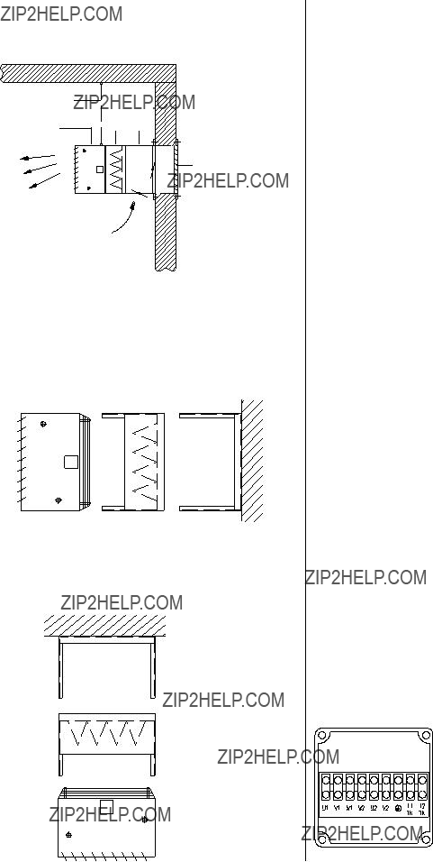
Sample Assemblies
Circulation / Fresh air mode via the outside wall
Electric Connection
The requirements of the local energy supply company as well as installation requirements specific for each
Wall
AG
The
unit must be observed.
The electrical connection may only be made by trained and authorised personnel.
Restriction of guarantee!
In cases of
Connecting the units
Wall assembly
In circulation mode with FK filter and KO bracket
Ceiling assembly
In circulation mode with FK filter and KO bracket
KO
FK
PWW
Standard REMKO PWW models are equipped with ax- ial fans that have external rotary current motors for a voltage of 400 V / 3~ / 50 Hz.
Switching the two speeds of the rotary current motor is done with a Y / ??? switch.
Integrated thermal contacts protect the motor. They switch off the fan motor at a winding temperature of 130 ??C in connection with a suitable switching device (accessory).
The rotary current motors are connected to the corre- sponding switching units in accordance with the respec- tive electrical wiring diagrams.
Connecting several units
If necessary, several units (even of different sizes) can be operated at the same time via a switching unit (accessory).
The overall capacity of the connected units may not, however, exceed the maximum electrical capacity of the corresponding switching unit.
For thermal motor protection, the thermal contacts of all motors are to be connected in a row. Follow the sepa- rate wiring diagrams.
There can never be more than one external regulating mechanism per switching unit (thermostat, day/night regulator, etc.) connected at a single time!
Terminal boxes on the unit
The corresponding power fuse in the power supply line to the switching unit must comply with the valid requirements.
The connections in the termi- nal box are to be connected with the corresponding switch- ing unit (accessory).
6

4.Make sure that hot surfaces, e.g. the supply lines, are protected against unintentional contact.
5.Ensure that the unit???s electrical wiring has been Shutting Down the Unit made in accordance with the relevant guidelines and
7

Service and Care
REMKO PWW units require virtually no maintenance when operated normally. They should, however, be checked regularly and, if necessary, cleaned, to ensure proper operation.
Important precautions prior to maintenance work
Perform the following steps prior to all service work:
1.Separate all poles of the unit from the power supply and secure it from being switched on by unauthor- ised persons.
It is not adequate to switch the unit off via the control switch on the switching unit!
2.Wait until the fan stops.
3.Turn off the flow of water and secure it from being opened on by unauthorised persons.
4.Wait until the
Do not flood the motor and the housing. Do not damage or bend the fan blades or plate fins.
Cleaning materials
???Only clean the unit when dry or with a slightly moist towel and a soap solution.
???Never use
???Do not use abrasive cleaners or cleaners that con- tain solvent.
???Even when the unit is extremely dirty, only use suit- able cleaning materials.
General care
???Keep the inside and outside of the unit free of dust and other deposits.
???Keep the air intake and outlet openings from being blocked.
???Check the protection grilles and the
???Inspect any mounted filters.
Clean or exchange if necessary.
Cleaning the unit
1.Clean the air intake openings and the air outlet plate fins.
2.Clean the fan blades.
If necessary, dismantle the motor or protective grille beforehand.
3.Clean the fins of the
4.Remove extreme dirt on the fan and plate fins with a soap solution.
5.Mount the motor or the protective grille with the fan.
Make sure that the distance between the fan blades and the housing is the same all the way around.
6.Clean or replace the pocket filter (accessory) if there is one.
7.To do this, loosen the screws of the filter housing and take the filter out.
Maintenance
Replacing the fan
1.Disconnect the electrical connection of the motor.
2.Remove the protective grille with the fan from the unit housing.
3.Remove the fan from the protective grille.
4.Mount the new fan on the protective grille.
5.Reattach the protective grill with the fan to the unit housing.
6.Reconnect the motor.
Replacing the
1.Disconnect the electrical connection of the motor.
2.Drain the
3.Remove the accessories on the air intake and outlet sides and take the unit out of the bracket (mount).
4.Remove the rear wall with the fan.
5.Loosen the attachment screws of the heat- exchanger and take out the
6.Insert the new
7.Reconnect the motor.
Inspection following maintenance:
???The fan wheel must be able to rotate freely in the fan housing.
???The distance between the fan blades and the fan housing must be the same.
???The motor must rotate in the direction of the arrow.
???After service and maintenance is complete, an elec- trical safety test must be conducted in accordance with VDE 0701.
8
Technical Data
1) Measurement at intervals of 5 m, measuring room volume 800 m??, average reverberation time 1.4 s
9

Accessories
The units are outfitted at the factory with horizontal air outlet flaps.
The individually adjustable fins allow the flow of warm air to be aimed in two directions.
Air outlet accessories
Air outlet flap B (horizontal/vertical)
Installing the flap allows air to be directed across longer distances. The vertical and horizontal arrangement of the fins make it possible to direct the air in up to 4 direc- tions
When retrofitting, the fins of the existing air outlet flap must be removed.
HG 4 air outlet cover
This air outlet cover makes it possible for air to be dis- tributed evenly in 4 directions when the unit is mounted at a low level.
The air outlet cover may not be used at mounting heights of more than 5.0 m.
When retrofitting, the fins of the existing air outlet flap must be removed.
PWW
HG 4
AD ceiling air outlet nozzle
The ceiling air outlet nozzle makes it possible to con- centrate the warm air flow and is used at higher assem- bly heights and in larger halls.
When retrofitting, the fins of the existing air outlet flap must be removed.
PWW
AD
Air intake accessories
FK filter box
The filter box with pocket filter is designed for direct at- tachment to the unit.
The pocket filter is pulled out on the side.
The filter medium of the pocket filter can be regener- ated and corresponds to the filter class EU 3.
Maintenance of the pocket filter
Depending on the operating conditions, the pocket filter must be checked at regular intervals and, if necessary, cleaned or replaced.
EF replacement pocket filters for the units:
PWW 4030 Ref. No. 1686253 PWW 4050 Ref. No. 1686254 PWW 4080 Ref. No. 1686255 PWW 4100 Ref. No. 1686256
Information about the FK filter box
How dirty the pocket filter is can be monitored via a dif- ferential pressure switch (special accessory)
When the final pressure differential is reached, the pocket filters must be replaced by new filters in the same class.
MLK
The MLK
The ratio of outside air to circulation air can be set manually with the
Maintenance of the
When operating the
10
Maximum ambient temperature 55?? C.
Prior to assembly, the pipe insulation in the area where the sensor is to be installed must be removed. The parts necessary for assembly such as tension strap, clamps, etc., are supplied with the unit.
Technical data:
Adjustment range 25 to 95 ??C, switching differential adjustable.
Maximum ambient temperature 70?? C.
11

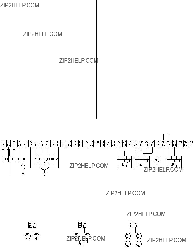
MSRD 2.5 switching unit
Rotary current 400 volt, fan
Design
Plastic housing, protection type IP 41.
Protective insulation in accordance with VDE, plate with symbols for switching positions, incoming power and protective conductor terminals, main contactor, control switch with the functions ???Off/Speed 1/Speed 2???, control fuse, operating light (goes out when there is a fan mal- function and/or power interruption to the switching unit), motor output terminals, connection terminals for thermal contacts and room thermostat.
Switching on again after a problem
Each time the power supply is interrupted or the fan malfunctions, the fan reset button has to be pressed once.
Switching and wiring diagram
Group switching
The switching unit is suitable for group switching. Sev- eral motors wired the same way can be connected to one switching unit.
The total capacity of the connected motors may not ex- ceed the permissible switch capacity of the switching unit. The thermal contacts of all motors are to be con- nected in a row.
Important information about safe operation
Grounding and earthing or protective wiring and fuse protection must be done by the customer in accordance with the requirements of the VDE as well as the respon- sible EVU.
The electrical unit connections must be performed by authorised personnel in the line with the valid require- ments in compliance with local laws and in accordance with the wiring diagrams.
Thermal protections for 2 units
1 3 5
K1
13
14
Thermal protection for 4 units
Connect other thermal contacts in a row
K1
2 4 6
PE L1 L2 L3 N
1 2 3 4 5
Incoming power 400V/3/N/PE 50HZ
Grounding in accordance with local requirements
F1
6,3A
12
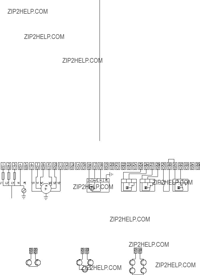
SW 2.1 D switching unit
Rotary current 400 volt, fan
Design
Plastic housing, protection type IP 65.
Protective insulation in accordance with VDE, front plate with symbols for switching positions and operating modes, power input and protective conductor terminals, main contactor, speed selector with the functions ???Speed 1 / Speed 2???, control fuse, operating and mal- function lights, operating mode switch with the functions ???Off / Release / Thermostat / Continuous Operation???, control relay, terminals for the motor output, connection terminals for the thermal contacts, room thermostats and frost protection thermostats.
Functionality
The frost protection thermostat switches the fan off.
Wiring diagram
Switching on again after a problem
Each time the power supply is interrupted or the fan malfunctions, the operating mode switch has to be reset to ???0/Release???!
Group switching
The switching unit is suitable for group switching. Sev- eral motors wired the same way can be connected to one switching unit.
The total capacity of the connected motors may not ex- ceed the permissible switch capacity of the switching unit. The thermal contacts of all motors are to be con- nected in a row.
Important information about safe operation
Grounding and earthing or protective wiring and fuse protection must be done by the customer in accordance with the requirements of the VDE as well as the respon- sible EVU.
The electrical unit connections must be performed by authorised personnel in the line with the valid require- ments in compliance with local laws and in accordance with the wiring diagrams.
Wiring diagram of the thermal contacts
13
SW 2.2 DSK switching unit
Rotary current 400 volt, fan
Design
Plastic housing, protection type IP 65.
Protective insulation in accordance with VDE, front plate with symbols for switching positions and operating modes, power input and protective conductor terminals, main contactor, speed selector with the functions ???Speed 1 / Speed 2???, control fuse, operating and mal- function lights, operating mode switch with the functions ???Off / Release / Thermostat / Continuous Operation???, control relay, terminals for the motor output, connection terminals for the thermal contacts, room thermostats, frost protection thermostats,
Functionality
The
The frost protection thermostat closes the flaps switches the fan off.
Wiring diagram
Switching on again after a problem
Each time the power supply is interrupted or the fan malfunctions, the operating mode switch has to be reset to ???0/Release???!
Group switching
The switching unit is suitable for group switching. Sev- eral motors wired the same way can be connected to one switching unit.
The total capacity of the connected motors may not ex- ceed the permissible switch capacity of the switching unit. The thermal contacts of all motors are to be con- nected in a row.
Important information about safe operation
Grounding and earthing or protective wiring and fuse protection must be done by the customer in accordance with the requirements of the VDE as well as the respon- sible EVU.
The electrical unit connections must be performed by authorised personnel in the line with the valid require- ments in compliance with local laws and in accordance with the wiring diagrams.
Wiring diagram of the thermal contacts
14
REMKO GmbH & Co. KG
Klima- und W??rmetechnik
32791 Lage, Im Seelenkamp 12
32777 Lage, PO Box 1827