Multi Format Digital HD
Video Cassette Recorder
Operating Instructions (Hardware)
Before operating this product, please read the instructions carefully and save this manual for future use.
VQT0F74
Multi Format Digital HD
Video Cassette Recorder
Operating Instructions (Hardware)
Before operating this product, please read the instructions carefully and save this manual for future use.
VQT0F74

For your safety (General)
Since this VTR is designed for metal tapes only, make sure that only the designated tapes are used. An or- dinary VHS tape cannot be used. Removal of the covers on electrical appliances for maintenance purposes may lead to electric shocks.
Personnel should therefore adhere strictly to the normal safety precautions.
Some
WARNING:
???TO REDUCE THE RISK OF FIRE OR
SHOCK HAZARD, DO NOT EXPOSE THIS
EQUIPMENT TO RAIN OR MOISTURE.
???TO REDUCE THE RISK OF FIRE OR
SHOCK HAZARD, KEEP THIS EQUIPMENT
AWAY FROM ALL
STORE ONLY IN LOCATIONS WHICH ARE
NOT EXPOSED TO THE RISK OF DROP-
PING OR SPLASHING LIQUIDS, AND DO
NOT PLACE ANY LIQUID CONTAINERS
ON TOP OF THE EQUIPMENT.
CAUTION:
Do not install or place this unit in a book- case,
THIS APPARATUS MUST BE GROUNDED
To ensure safe operation the
Extension cords used with the equipment must be
The fact that the equipment operates satis- factorily does not imply that it is grounded, and the installation is not necessarily safe. For your safety, if in any doubt about the effective grounding of the equipment or power outlet (socket), please consult a qualified electrician.
CAUTION:
TO REDUCE THE RISK OF FIRE OR SHOCK
HAZARD AND ANNOYING INTERFERENCE,
USE THE RECOMMENDED ACCESSORIES ONLY.
CAUTION:
THE AC OUTLET (MAINS SOCKET) SHALL
BE INSTALLED NEAR THE EQUIPMENT
AND SHALL BE EASILY ACCESSIBLE.
CAUTION:
TO REDUCE THE RISK OF FIRE OR SHOCK
HAZARD, REFER MOUNTING OF THE OP-
TIONAL BOARD AND CHANGE OF THE
SWITCH SETTING INSIDE THE UNIT TO AU-
THORIZED SERVICE PERSONNEL.
CAUTION:
EVEN WHEN THE POWER SWITCH IS IN
THE OFF POSITION, A SMALL CURRENT
FLOWS THE FILTER CIRCUIT.
1 is the safety information.
Operating precaution
Operation near any appliance which generates strong magnetic fields may give rise to noise in the video and audio signals. If this should be the case, deal with the situation by, for instance, moving the source of the magnetic fields away from the unit before operation.
??? 2 ???
For your safety
For USA and Canada
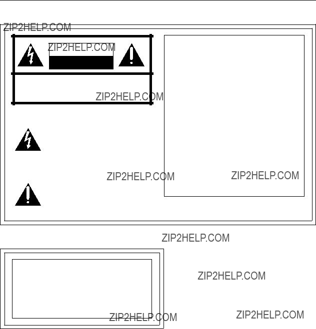
The lightning flash with arrowhead sym- bol, within an equilateral triangle, is in- tended to alert the user to the presence of uninsulated ???dangerous voltage??? with- in the product???s enclosure that may be of sufficient magnitude to constitute a risk of electric shock to persons.
The exclamation point within an equilat- eral triangle is intended to alert the user to the presence of important operating and maintenance (servicing) instructions in the literature accompanying the ap- pliance.
FCC NOTE:
This device complies with Part 15 of the FCC Rules. To assure continued compliance follow the attached installation instructions and do not make any unauthorized modifications.
This equipment has been tested and found to comply with the limits for a Class A digital de- vice, pursuant to Part 15 of the FCC Rules. These limits are designed to provide reason- able protection against harmful interference when the equipment is operated in a commer- cial environment. This equipment generates, uses, and can radiate radio frequency energy and, if not installed and used in accordance with the instruction manual, may cause harmful interference to radio communications. Operation of this equipment in a residential area is likely to cause harmful interference in which case the user will be required to correct the interference at his own expense.
For Europe
CAUTION:
DO NOT REMOVE PANEL COVER BY UN-
SCREWING
To reduce the risk of electric shock, do not remove cover. No user serviceable parts inside. And do not insert fingers or any other objects into the video cassette holder.
1 is the safety information.
??? 3 ???
For your safety (Europe)
Caution for AC Mains Lead
FOR YOUR SAFETY PLEASE READ THE FOLLOWING TEXT CAREFULLY.
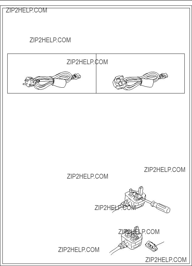
This product is equipped with 2 types of AC mains cable. One is for continental Europe, etc. and the other one is only for U.K.
Appropriate mains cable must be used in each local area, since the other type of mains cable is not suitable.
FOR U.K. ONLY
This appliance is supplied with a moulded three pin mains plug for your safety and convenience.
A 13 amp fuse is fitted in this plug.
Should the fuse need to be replaced please ensure that the replacement fuse has a rating of 13 amps and that it is approved by ASTA or BSI to BS1362.
Check for the ASTA mark ?? or the BSI mark ?? on the body of the fuse.
If the plug contains a removable fuse cover you must ensure that it is refitted when the fuse is replaced.
If you lose the fuse cover the plug must not be used until a replacement cover is obtained.
A replacement fuse cover can be purchased from your local Panasonic Dealer.
IF THE FITTED MOULDED PLUG IS UNSUITABLE
FOR THE SOCKET OUTLET IN YOUR HOME THEN
THE FUSE SHOULD BE REMOVED AND THE PLUG
CUT OFF AND DISPOSED OF SAFELY. THERE IS A
DANGER OF SEVERE ELECTRICAL SHOCK IF
THE CUT OFF PLUG IS INSERTED INTO ANY 13 AMP SOCKET.
If a new plug is to be fitted please observe the wiring code as shown below.
If in any doubt please consult a qualified electrician.
WARNING: THIS APPLIANCE MUST BE EARTHED.
IMPORTANT: The wires in this mains lead are coloured in accordance with the following code:
Blue:Neutral
Brown:Live
As the colours of the wires in the mains lead of this appliance may not correspond with the coloured markings identifying the terminals in your plug, proceed as follows:
???The wire which is coloured
???The wire which is coloured BLUE must be connected to the terminal in the plug which is marked with the letter N or coloured BLACK.
???The wire which is coloured BROWN must be con- nected to the terminal in the plug which is marked with the letter L or coloured RED.
How to replace the fuse
1. Open the fuse compartment with a screwdriver.
2. Replace the fuse.
Fuse
??? 4 ???

Contents
For your safety . . . . . . . . . . . . . . . . . . . . . . . . . . . . . . . . . . . . . . . . . . . . . . . . . . . . . . 02 Features . . . . . . . . . . . . . . . . . . . . . . . . . . . . . . . . . . . . . . . . . . . . . . . . . . . . . . . . . . . 06 Controls and their functions
???Front Panel. . . . . . . . . . . . . . . . . . . . . . . . . . . . . . . . . . . . . . . . . . . . . . . . . . . . . . . . 08 ???Connector section . . . . . . . . . . . . . . . . . . . . . . . . . . . . . . . . . . . . . . . . . . . . . . . . . . 14 Connections
???Connections for a single unit . . . . . . . . . . . . . . . . . . . . . . . . . . . . . . . . . . . . . . . . . . 18 ???Connections for 2 units . . . . . . . . . . . . . . . . . . . . . . . . . . . . . . . . . . . . . . . . . . . . . . 19 ???Connection with an editing controller . . . . . . . . . . . . . . . . . . . . . . . . . . . . . . . . . . . . 20 Tapes . . . . . . . . . . . . . . . . . . . . . . . . . . . . . . . . . . . . . . . . . . . . . . . . . . . . . . . . . . . . . 21 Recording . . . . . . . . . . . . . . . . . . . . . . . . . . . . . . . . . . . . . . . . . . . . . . . . . . . . . . . . . . 22 Playback . . . . . . . . . . . . . . . . . . . . . . . . . . . . . . . . . . . . . . . . . . . . . . . . . . . . . . . . . . . 28 Basic operations . . . . . . . . . . . . . . . . . . . . . . . . . . . . . . . . . . . . . . . . . . . . . . . . . . . . . 29 Manual Editing . . . . . . . . . . . . . . . . . . . . . . . . . . . . . . . . . . . . . . . . . . . . . . . . . . . . . . 35 Manual audio cross editing. . . . . . . . . . . . . . . . . . . . . . . . . . . . . . . . . . . . . . . . . . . . . 37 Automatic insert/assemble editing . . . . . . . . . . . . . . . . . . . . . . . . . . . . . . . . . . . . . . . 38 Audio split editing . . . . . . . . . . . . . . . . . . . . . . . . . . . . . . . . . . . . . . . . . . . . . . . . . . . . 40 Variable memory Function . . . . . . . . . . . . . . . . . . . . . . . . . . . . . . . . . . . . . . . . . . . . . 42 Connector signals. . . . . . . . . . . . . . . . . . . . . . . . . . . . . . . . . . . . . . . . . . . . . . . . . . . . 44 Video head cleaning . . . . . . . . . . . . . . . . . . . . . . . . . . . . . . . . . . . . . . . . . . . . . . . . . . 49
??? 5 ???

Features
This HD VTR is a
By
Only playback is possible with 576/50i (4 audio channels) format tapes which have been recorded using the VTR
Simultaneous output of HD
In the case of the 1080/23.98p, 1080/24p and 1080/25p formats, the 1080/23.98psf, 1080/24psf and 1080/25psf (Progressive Segmented Frame) formats which divide the frames into two segments every 1/47.96, 1/48 and 1/50 of a second, respectively, for interfacing are also used.
Picture/sound quality at a reasonable price
???High picture quality digital recording of signals complying with studio standard
The
Virtually
???Compact size, light weight and low power consumption
The unit is compact (height equivalent to 5U, depth at 201/2q), lightweight (69.96 lbs), low in power consump- tion (260 W) and easy to handle.
???High cost performance
In addition to featuring the basic functions and performance of HDD5, this HDVTR makes it possible to switch between the 1080/23.98p
???Digital audio with high sound quality
A high sound quality with a dynamic range of 100 dB is delivered by 20
With the 1080/59.94i, 480/59.94i, or 720/59.94p system format, either the
???Compact 1/2z tape cassette
Two sizes of cassette, [L: 124 minutes (1080/59.94i, 720/59.94p and 480i), 149 minutes (1080/50i,
1080/25p), 155 minutes (1080/23.98p and 1080/24p), 112 minutes (576/50i) and M: 63 minutes
(1080/59.94i, 720/59.94p and 480/59.94i), can be used with this unit: this enables the size best suited to the intended application to be selected. The compact 1/2q cassette takes up minimal storage space and offers ex- cellent handling ease.
??? 6 ???

Features
I/O specifications and interfaces
???Serial digital I/O facilities
The unit is equipped with
???Format converter function
A format converter board has already been equipped in the unit as a standard accesory. This facilitates con- version between HD and SD, and it makes the integrated production of
In addition to the composite analog signals, a serial digital interface (SDI signals) which can switch the mul- tiplex transfer of audio signals ON or OFF is included in the SD output signals. SDI signals enable digital con- nection to a DVCPRO/D5VTR.
???AES audio input/output facilities
Separate digital audio inputs and outputs are provided for each of the 4 (8) channels, and standard interfac- ing with a variety of digital audio units is possible. (8 channels with 1080/23.98p, 1080/24p, 1080/25p, 1080/50i and 576/50i formats. 4 channels/8 channels with 1080/59.94i, 720/59.94p and 480/59.94i formats.)
???Remote control
In addition to the standard
Slow motion, search and editing functions
???Slow motion/jog
The incorporation of Panasonic???s unique AT (auto tracking) mechanism makes
???50t shuttle search
Shuttle search is possible at up to 50k normal tape speed in the forward or reverse direction.
???Simultaneous playback monitoring
Simultaneous playback monitoring of video, digital audio, time code and CTL signals is possible.
???Automatic editing functions
A full range of editing modes are provided including assemble, insert, audio split and variable memory.
???Multi cue points
One hundred cue points can be marked for searches and prerolling.
Operation and maintenance
???Channel condition monitoring
The error rate is monitored at all times. When the setting is exceeded, an indicator on the front panel lights to warn the operator that the tape is approaching the end of its service life or that the heads are clogged.
Color bar signals and other test signals, which come in handy for conducting maintenance and adjustments and for checking the connections, are generated internally.
??? 7 ???

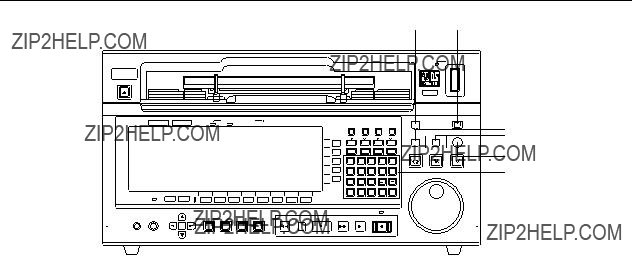
Controls and their functions
Front panel
(7)
(8)
(9)
L/R selector buttons ???jack.
???They are used to select which of the 5 (9) channel [4 (8) digital audio signal channels and 1 cue audio signal channel] signals is to be output to L/R.
???Each time the L (or R) button is pressed, the selected output L (or R) signal changes in the sequence of CH1, CH2, CH3, CH4 (CH5, CH6, CH7, CH8)??, and CUE.
??When a
???The channel now selected can be monitored by observing the L and R indica- tions on the display panel.
???L and R displays are highlighted corresponding to the channels now selected on the display panel.
???Default settings: CH1 for L and CH2 for R.
<Note>
1080/23.98p, 1080/24p, 1080/25p, 1080/50i and 576/50i formats are digital audio 8ch.
Either the
??? 8 ???

Controls and their functions
Front panel
(13)
1
(10)(11)(12)
(13)
2
(10)Headphone jack ???The stereo headphones are connected to this M6 headphone jack.
(11)Headphone VR ???This volume control is used to adjust the headphones output level and monitor-
ing output level.
???The headphone output level and the monitoring output level are interlinked [when the F7 (A. MONI) key on the AUDIO OUT MONITOR menu is set to VAR].
(16)Error display lamps ???These lamps light in response to the number of errors.
(channel condition) 1 Lights during normal operation (when the error value is minimal).
2 Lights when the number of inner errors has increased.
3 Lights when the number of video outer errors has increased.
4Lights when the number of audio outer errors has increased.
(17)SERVO lamp ???This lights when the servo is locked.
??? 9 ???
Controls and their functions
(18)Number keys ???These are used to enter numbers.
(0 to 9)
??? 10 ???
Controls and their functions
(33) (35)
(32) (34)
(28)  (29)
(29)  (30)
(30)
(31)
(24)HOME button
(25)MULTI CUE button
(26)ASSEM (ASSEMBLE) button
(27)INSERT button
(28)VIDEO IN
(29)VIDEO OUT
(30)AUDIO IN
(31)AUDIO OUT
(32)TC/CHR
(33)SET UP
(34)TEST
(35)DIAG
??? 11 ???

Controls and their functions
Front panel
(36)
(37)
(38)
(39)
(40) (41)(42)(43)
(36)SHTL button
(37)JOG button
(38)VAR button
(39)SEARCH dial
(40)EXECUTE button This executes the variable memory operation etc.
(41)REVIEW/PREVIEW This previews what has been recorded before editing or reviews the recording
(42)PREROLL button (The tape is cued up when the F key and PREROLL keys are pressed.)
(43)ENTRY button
??? 12 ???

Controls and their functions
Front panel
(44)(45)(46)(47)(48)(49)(50)
(44)REW button
(45)STAND BY button
(46)STOP button
(47)FF button
(48)PLAY button
(49)REC/EDIT button
(50)REC INHIBIT lamp
??? 13 ???

Controls and their functions
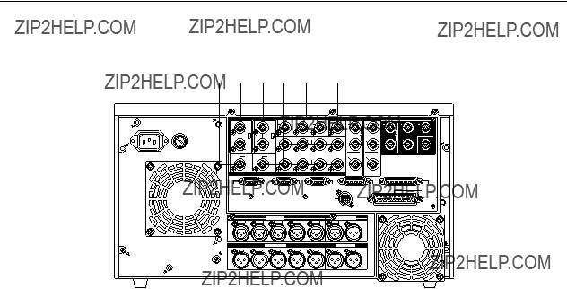
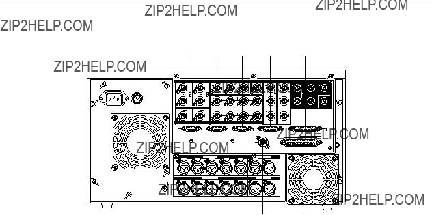
Connector section
(1) (2)
(8)HD SDI IN connectors (BNCt2) This is an active through input for HD SDI serial digital signals.
(9)HD SDI OUT1, 2, 3 connectors For output of HD SDI serial digital signals.
(BNCt3)
(10)HD SDI MONITOR OUT connector For output of HD SDI serial digital signals.
(11)DIGITAL AUDIO IN CH1/2, CH3/4 Input of digital audio signals according to the AES standard.
(CH5/6, CH7/8)??1 connectors (BNCt4)
(12)DIGITAL AUDIO OUT CH1/2, Output of digital audio signals according to the AES standard.
CH3/4 (CH5/6, CH7/8)??2 connectors (BNCt4)
??1The items in brackets are not operative with 1080/59.94i audio (4 channels), 720/59.94p audio (4 channels) or 480/59.94i audio (4 channels) format.
??2A function is provided to copy the sound of channels 1 through 4 onto channels 5 through 8 when the 1080/59.94i audio (4 channels), 720/59.94p audio (4 channels) or 480/59i audio (4 channels) format is used. For further details, refer to the AUDIO OUT SET UP menu in the operating instructions for the software.
??? 14 ???
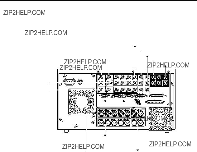
Controls and their functions
Connector section
(15)(13)(14)(16)(17) (18)
Analog input/output section
(13)HD REF IN connectors (BNCt2)
(14)SD REF IN connectors (BNCt2)
(15)HD REF OUT terminal (BNCt1)
(16)SD REF OUT terminal (BNCt1)
(17)VIDEO OUT1, 2, 3 connectors (BNCt3)
(18)WFM (waveform) connector
Input of
Input of black burst??1 signals as the SD reference signals. A
Output of HD SYNC
Output of black burst??2.
Composite video signal output.
For OUT3, superimpose output is also possible.
Signals output to the waveform monitor.
??1When the normal black burst signal (59.94 Hz) is input as the SD REF signal with the 1080/24p system, asynchronization and a picture error will result.
??2This signal is not output with the 1080/24p system.
??? 15 ???

Controls and their functions
Connector section
Analog input/output section
(20)CUE IN connector Audio signal input for the analog cue channel.
(XLR 3P)
(21)TIME CODE IN Time code signal input. connector (XLR 3P)
(24)TIME CODE OUT Time code signal output. connector
(XLR 3P)
(25)MONITOR OUT These are the audio monitor connectors. L, R audio output is made.
??? 16 ???
Controls and their functions
Connector section
Remote control section
(27)REMOTE OUT
(28)REMOTE IN/OUT
(29)V/A CONTROL Encoder remote
(31)CONTROL PANEL For connection of the cable of a control panel.
connector (20P) The control panel connector enables the connectors on the front panel and
connectors on the rear panel to be connected, and when these connectors are simultaneously connected, it is possible to switch between them using the menu.
ONoteN
The
??? 17 ???
Connections
Connection for a single unit
Press the REMOTE button on the front panel to turn the lamp (LOCAL) off.
Digital audio input
Digital audio output 
??? 18 ???
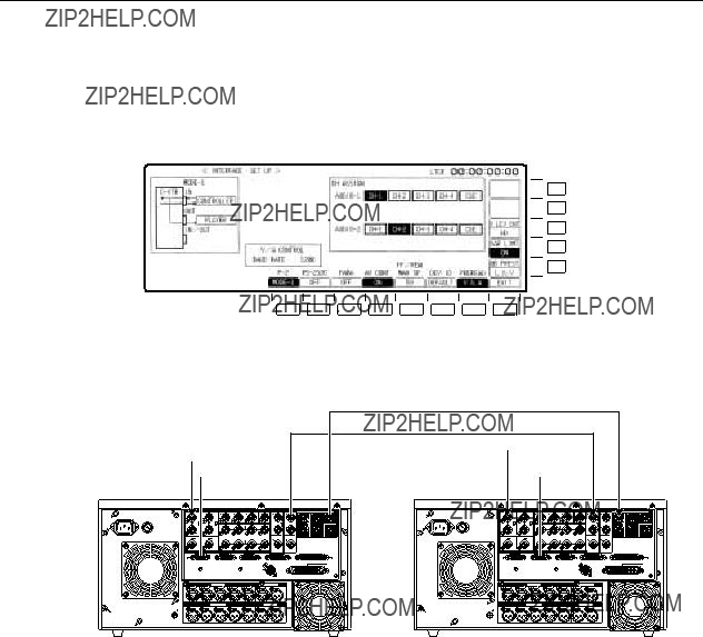
Connections
Connection for 2 units
Source side Press the REMOTE button at the front panel to light the lamp (REMOTE). Recorder side Press the REMOTE button at the front panel to extinguish the lamp (LOCAL).
When performing automatic editing with
F13
F12
F11
F10
F9
HD SDI DIGITAL VIDEO/AUDIO
SD SDI DIGITAL VIDEO/AUDIO
???When matching the CF (color frame) of SD output and time code output phase, also make SD reference matching. Then select SD REF as the OUT REF setting on the HOME SET UP menu.
??? 19 ???
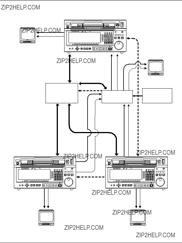
Connections
Connection with an editing controller
Recorder
Audio monitor signal
Audio output signal
AV monitor
HD reference signal generator
Reference signal
Source unit
Source unit
???Please use LTC: VITCi as the time code setting on the controller side.
???When 720/59.94p mode has been set, input the SD_REF (BB) signal as the reference signal.
??? 20 ???
Tapes
There are two tape types: M and L.
75 minutes (1080/25p and 1080/50i), 79 minutes (1080/23.98 and 1080/24p)
149 minutes (1080/25p and 1080/50i), 155 minutes (1080/23.98p and 1080/24p) Align the cassette with the marks on the unit???s insertion slot and push it in gently.
The cassette tape will be loaded automatically.
Prohibiting recording on a tape (when pins A and B are at the ???up??? position)
AB
Use a screwdriver to push down the accidental erasure preven- tion pins, turn them 90?? counterclockwise, and then lift the screwdriver to set the pins at their ???up??? positions.
The recording prohibition status is displayed on the MANUAL EDIT SET UP menu and the AUTO EDIT SET UP menu respec- tively.
ONoteN
C bit pin: Raised position )
C
(See figure below)
Lowered position )
audio version, 720/59.94p:
1080/25p, 1080/50i, 480/59.94i:
??The D5 VTR
Enabling recording (when pins A and B are at the ???down??? position)
Use a screwdriver to push down the accidental erasure preven- tion pins, turn them 90?? clockwise, and then lift the screwdriver to
??? 21 ???

Recording
Preparation
???Release the recording inhibit mode
???Confirm that the REC INHIBIT lamp has gone out.
REC INHIBIT 
If the lamp has not gone out, set the positions of the cassette???s accidental erasure prevention pins and the F13 (REC INH) set- ting on the HOME menu to the recording enabled status.
???Selecting the input signals and adjusting their levels
???Select the video input signal (INT SG or DIGITAL) on the VIDEO IN menu.
???Select the audio input signal on the AUDIO IN PCM menu and the AUDIO IN CUE menu. ???Adjust the audio input signal level on the AUDIO IN menu.
Adjust the audio input signal levels for the digital audio channels CH1 to CH4 (or
Normally, UNITY should be selected.
???When adjusting the recording levels, select the channel whose level is to be adjusted using the AUDIO IN menu (for example, to adjust the PCM CH1 level, press the F1 key to set to white-
???The level meter display can be switched.
The level meter display can be set to FULL or FINE using the F7 (SCALE) key on the AUDIO IN SET UP menu or the F7 (SCALE) key on the AUDIO OUT SET UP menu.
??? 22 ???

Recording
Preparation
???Setting the time code
???Press the F4 (TC/CTL) key on the HOME menu to select TC.
???Select the internal or external time code on the TC/CHR menu and set the generating mode.
Operation
(1)Press the PLAY button while pressing the REC/EDIT button. Recording will start.
PLAY REC/EDIT
(2)Recording stops when the STOP button is pressed.
If the JOG, SHTL, or VAR button is pressed in place of the STOP button, operation is di- rectly transferred to the mode that corresponds to the respective button.
??? 23 ???

Recording
Simultaneous playback monitoring
???Video monitoring
???Set VIDEO during recording to TAPE on the VIDEO OUT HD SET UP STATE menu.
???Audio monitoring
???Set AUDIO during recording to TAPE on the AUDIO OUT SET UP STATE menu.
VIDEO
D. AUDIO
REC
TAPE
TAPE
???The digital audio and the digital video signals are interlinked at all times. They can not be set separately.
???Simultaneous playback of the analog cue signal is not possible. ???Simultaneous playback monitoring is not possible when the F1
(OUTPUT) key on the HOME menu is set to EE.
???Even when the state menu setting is EE1 or EE2, simultaneous playback monitoring of both the video and audio signals is pos- sible by setting the F1 (OUTPUT) key on the HOME menu to TAPE.
???Checking the input signals
???To monitor the input signals during recording:
(1)Connect a TV monitor to the serial monitor connector. Connect the audio monitor connector to the monitor speaker.
(2)Press the INPUT CHECK button.
INPUT CHECK
While this button is held down, the video signal can be checked using the serial monitor output connector.
???Only the audio signal selected by the L and R buttons can be monitored (via the audio monitor connector or the headphone connector).
*In the HD mode, only the
???or
AUDIO OUT # F8 # F12
??? 24 ???

Recording
This flowchart shows the steps for recording the digital signals which are supplied to the unit from an exter- nal digital device.
11. Check the connections.
12. Turn on the power.
13. After making sure that no cassette tape is inserted in this unit, set the system frequency 59.94, 23.98, 24, 25 or 50 by F1 (FREQ) key of the SYSTEM SET UP menu.
F13
F12
F11
F10
F9
The frequency setting is possible when the F1 key is pressed. Select the frequency by cursor keys [3, 4] and press the ENT key, then the frequency is secured. In 59 Hz mode, the selection window will be further displayed (1080i/525i/720p). Select the format by the cursor key, and press the ENT key to secure the format. Then, select its
In the 23.98 Hz, 24 Hz or 25 Hz mode, a window appears offering the user the option of se- lecting PsF or P for the VIDEO signal interface format. When the format is selected using the cursor keys [3, 4] and the ENT key is then pressed, the format is entered. In the same way, the HD MAIN output and HD MONI output formats are selected using the cursor keys [3, 4] and then entered by pressing the ENT key.
(The table below lists the possible combinations of the output signals of the video output connectors.)
How to display the ???SYSTEM SET UP menu:
??1The 1035/59.94i format signals cannot be recorded on this VTR but a tape recorded using the
??21080/23.98p 1080/25p and 1080/24p format tapes can be played back and 1080/50i format signals can be output automatically. ??31080/25p tapes can be played back and a variety of images can be output.
??? 25 ???

Recording
14. Insert a
It should be borne in mind that the
Note that when the cassette tape is inserted, it is not possible to change the system frequency which was set using the F1 (FREQ) key on the SYSTEM SET UP menu of the previous page.
15. Press the F13 (REC INH) key on the HOME menu to set to ???FREE???.
REC INH
FREE
16. Perform input signal setting with the F1 to F6 (CH1 to CH4) keys on the AUDIO IN PCM INPUT SELECT menu. [In the case of the 1080/23.98, 1080/24p, 1080/25p, 1080/50i and 576/50i formats or 1080/59.94i
F13
F12
F11
F10
F9
17. When the input audio signal is to be mixed with the analog cue channel for recording, press the F9 (CUE) key on the AUDIO IN CUE INPUT menu to set it to
CUE
18. Adjust the audio input level on the AUDIO IN menu.
19. When the time code is to be recorded, perform the time
F13
F12
F11
F10
F9
10.To enter the time code default value as desired, press the cursor center key at the HOME menu and set the value.
11.When the preparation for the signals to be recorded has been established, press the REC/EDIT button and the PLAY button together.
Recording will start.
12.To stop recording at any time, press the STOP button.
??? 26 ???

Recording
???The REF synchronization specifications applying when the 1080/23p, 24p or 25p
???The
???The enhance and filter response picture quality adjustments do not work for
???Other signals cannot be superimposed onto HD monitor outputs using
???When PsF signals have been recorded using a PsF system format and they are subsequently played back using a
???Bear in mind that when recording 1080/50i signals using the 1080/25PsF system format, the signals will be recorded but the images will be blurred.
??? 27 ???

Playback
Operation
(1) Press the PLAY button.
(2)Playback stops when the STOP button is pressed.
If the JOG, SHTL, VAR, FF, or REW button is pressed in place of the STOP button, oper- ation is directly transferred to the mode that corresponds to the respective button.
???Monitoring the audio signals
???Select the audio channel for output from the AUDIO MONITOR L/R connector or the HEAD- PHONES jack using the L/R buttons. (The audio channel can be switched to the opposite direction when the L or R button is pressed while the F key is being held down.)
AUDIO MONITOR
L R
???Adjusting the audio level
Adjust the playback level of the digital audio CH1 to CH4 (or
To adjust the audio signal level, first press the F key all ocated to the channel concerned on the AUDIO OUT menu to highlight it, and then adjust the level using the ADJUST control.
The adjustment range is from j?? to i12 dB for digital audio sig- nals as well as for the analog cue signal.
???To adjust all digital audio signal playback levels together, ad- just with the ADJUST knob while pressing the AUDIO LINE OUT button.
???The level meter display can be switched between FULL and FINE.
Fine adjustment is possible by setting the F7 (SCALE) key on the AUDIO IN SET UP menu or the F7 (SCALE) key on the AUDIO OUT SET UP menu to ???FINE???.
??? 28 ???

Basic operations
???Stop
Press the STOP button.
The tape will stop.
???In order to protect the tape, the tape tension is automatically re- STOPleased (a process called ???loosening???) when the time selected by the F12 (STILL) key on the HOME SET UP menu has
elapsed. The READY lamp will flash.
???Furthermore, the READY OFF mode is automatically estab- lished when the time selected by the F13 (STBY OFF) key on the HOME SET UP menu has elapsed. The READY lamp will go out and the STOP lamp will light. (Refer to the item STAND- BY on this page.)
???FF/REW
Press the FF or the REW button.
???STAND BY
???When the STAND BY lamp is lit, the unit is in the STAND BY ON status.
STAND BY
STAND BY OFF mode is established automatically when the time selected with the F13 (STBY OFF) key on the HOME SET UP menu has elapsed and loosening status has been reached. (Refer to the item STOP on this page.)
???When the STAND BY lamp is not lit, the unit is in the STAND BY OFF status.
??? 29 ???

Basic operations
???Shuttle (SHTL)
(1) The unit is placed in the shuttle mode when the SHTL button is pressed and the lamp SHTLlights.
(2) Turn the search dial.
???The tape speed changes depending on the angle by which the dial is turned.
???The tape speed is displayed on the search indicator.
???The tape speed can be varied up to a maximum of n 50 times the normal tape speed.
???The maximum speed can be set by pressing the F6 (SHTL MAX SP) key on the PANEL SET UP menu.
(3)When the STOP, FF, REW, PLAY, JOG, or VAR button is pressed, operation is directly transferred to the mode that corresponds to the respective button.
???Jog
(1) The unit is placed in the JOG mode when the JOG button is pressed and the lamp lights.
JOG
(2) Turn the search dial.
???When the dial rotation is stopped, the unit is placed in the still- picture (STILL) mode.
???The tape protection mode is established after the
???The tape speed changes depending on the speed by which the dial is turned.
???The tape speed ranges from j2 times to i2 times of the nor- mal tape speed. In the range from j1 to i2 times of the nor- mal tape speed, the audio signals for all channels are output from the AUDIO OUT connectors.
(3) When the STOP, FF, REW, PLAY, SHTL, or VAR button is pressed, operation is directly
??? 30 ???
Basic operations
???Variable (VAR)
The variable mode is a
This operation may be initiated from STOP or PLAY mode or during normal recording.
VAR (1) The unit is placed in the variable mode when the VAR button is pressed and the lamp lights.
(2) Turn the search dial.
???The tape speed changes depending on the angle by which the dial is turned, and it is displayed on the search indicator.
???The tape protection mode is established after the
???Turning the dial enables shuttle operations across a range from j1 to i2 times of the normal tape speed. The audio signals for all channels are output from the AUDIO OUT connectors.
???The maximum speed can be set by pressing the F12 (VAR MAX SP) key on the PANEL SET UP menu.
(3)When the STOP, FF, REW, PLAY, JOG, or SHTL button is pressed, operation is directly transferred to the mode that corresponds to the respective button.
???Preset variable mode
???When the variable speed is preset, playback starts at the set speed when the VAR button is pressed.
(1)Set the desired speed by turning the search dial.
The tape speed changes depending on the angle by which the dial is turned. The speed is displayed on the search indicator.
(2)Press the VAR button. (The VAR lamp lights.) Playback will start at the set speed.
(3)To release the preset variable mode, turn the search dial. The normal variable mode will be established.
???The preset variable mode can be operated only in STOP or PLAY mode or during normal recording.
??? 31 ???

Basic operations
??? Tape speed override (TSO) function
This is a function for finely adjusting the normal playback speed in the range of n15%.
PLAY
??? Cue
(1)Press the PLAY button. Normal playback starts.
(2)Turn the search dial while pressing the PLAY button, or press the i or j keys. When using the search dial, the tape speed changes depending on the angle to which the search dial is turned. When using the i or j keys, the tape speed changes according to how long the key is pressed continously. The speed is displayed in numeric values on the search indi- cator.
(3)To return to normal playback, release the PLAY button.
This function sets any point on the tape for preroll and search operations.
When TC INPUT is set to the STANDARD mode*
(1)Press the cursor center key to display the cursor. The time code value will be highlighted.
Cursor center key
LTCR
00 : 00 : 00 : 00
(2)Move the cursor with the cursor key (4) to the CUE TIME display section. The cue display section will be highlighted.
CUE TIME
H M S F
Cursor
(3)Press the cursor center key again to change it to a bar cursor. Enter the cue point with the number keys.
ENTRY
CUE TIME
00 H 44 M 07 S 04 F
(4)Press the ENT key.
The cursor will disappear.
(5)Press the PREROLL button.
???When the PREROLL button is pressed,
PREROLL
start, and the tape will stop at the preroll point (the point pre- ceding the cue point by the preroll time).
???To stop at the cue point, either set the preroll time to ???0??? or press the F key and PREROLL button together. (This results in the
*The STANDARD mode is set using the F9 key on the PANEL SET UP menu. (This key can be set in either the STANDARD or REVERSE mode.)
??? 32 ???

Basic operations
When TC INPUT is set to the REVERSE mode*
(1)Press the cursor center key to display the cursor. The time code value will be highlighted.
(2)Move the cursor with the cursor key (4) to the CUE TIME display section. The cue display section will be highlighted.
CUE TIME
H M S  F
F
Cursor
(3)Press the cursor center key again to change it to a bar cursor. Enter the cue point with the number keys.
ENTRY
CUE TIME
00 H 44 M 07 S 04 F
(4)Press the ENT key.
The cursor will disappear.
(5)Press the PREROLL button.
*The REVERSE mode is set using the F9 key on the PANEL SET UP menu. (This key can be set in either the STANDARD or REVERSE mode.)
??? 33 ???

Basic operations
??? Correction of the cue point
When TC INPUT is set to the STANDARD mode
(1) Move the cursor to the place which is to be corrected.
CUE TIME
00 H 41 M 07 S 04 F
Cursor
(2) ENTER the new value with the number keys.
CUE TIME
00 H 44 M 07 S 04 F
(3) Press the ENT key.
???Cue points cannot be cleared.
When TC INPUT is set to the REVERSE mode
Partial corrections cannot be made for cue points.
Repeat the input starting from step (1) when TC INPUT on page 33 was set to the REVERSE mode.
??? 34 ???

Manual editing
Manual editing is a method used for editing which does not involve the REGISTRATION of edit points (IN/OUT points).
1.Check the connections.
2.Switch on the power.
3.Insert the cassette to be edited.
4.Press the F13 (REC INH) key on the HOME menu to set to FREE or NRML.REC.
REC INH
FREE
5.Select and adjust the input signals.
6.To record the time code, perform the time
7.To enter the desired default value for the time code, press the cursor center key at the HOME menu and set the desired value.
8.Press the ASSEMBLE or the INSERT button to display the INSERT/ASSEMBLE EDIT menu.
9.Press the F12 key on the INSERT (or the ASSEMBLE) EDIT menu to set to MANUAL EDIT, display the MANUAL EDIT menu, and highlight the F9 (INSERT or ASSEMBLE) key.
MANUAL
EDIT
10.When insert editing was selected in step 8 by pressing the INSERT button, press the F13 key on the INSERT MANUAL EDIT menu to display the INSERT MANUAL EDIT CH SELECT menu, and select the channels to be edited.
11.Set the editing timing with the F1 (TIMING) key on the INSERT (or ASSEMBLE) MANUAL EDIT SET UP menu.
TIMING
F2
??? 35 ???

Manual editing
12.Search the edit start (IN) point and set the picture to the still mode.
13.
14.Provide input of the editing source.
15.Press the PLAY button to place the unit into playback mode.
16.Press the REC/EDIT button at the edit start (IN) point. Editing will start.
17.To end editing, press the STOP or the REC/EDIT button.
??? 36 ???

Manual audio cross editing
Below is a flowchart showing the steps taken for editing in which audio signals are
1.Prepare for manual editing by referring to steps 1 to 14 in the manual editing flowchart.
2.Set the F13 (MODE) key on the INSERT (OR ASSEMBLE) MANUAL EDIT SET UP menu
to XFADE.
MODE
XFADE
3.Use the F12 (FD TIME) key on the INSERT (OR ASSEMBLE) MANUAL EDIT SET UP menu to set the fade time.
4. Refer to steps 15 to 17 of manual editing, and proceed with editing.
???For audio V fading, set the F13 (MODE) key on the INSERT (OR ASSEMBLE) MANUAL EDIT SET UP menu to VFADE.
???The settings for audio cross editing can be performed only when EE1 has been set as the EDIT REC status.
How to display the ???INSERT (or ASSEMBLE) AUTO EDIT SET UP menu:
??? 37 ???
Automatic insert/assemble editing
The following flowchart shows the operation for automatic insert editing or automatic assemble editing with two digital VTRs.
1.Check the connections.
2.Switch on the power to the player and to the recorder.
3.Insert the cassettes required for editing into the VTRs.
4.Press the REMOTE button on the player and set the button to REMOTE (lamp is lit).
REMOTE
5. Press the REMOTE button on the recorder and set the button to LOCAL (lamp is not lit).
REMOTE
6. Set the F3 (W/PLYR) key on the recorder???s INSERT (or ASSEMBLE) AUTO EDIT menu to
ON.
W/PLYR
ON
7.Set the F1
Set the
8. Set the F13 (REC INH) key on the recorder???s HOME menu to FREE or NRML.REC.
REC INH
FREE
9.Select and adjust the input signals on the recorder.
10.To record the time code, perform the time
11.To enter the desired default value for the time code, press the cursor center key at the recorder???s HOME menu and set the desired value.
How to display the ???INSERT (or ASSEMBLE) AUTO EDIT
??? 38 ???

Automatic insert/assemble editing
12.Press the INSERT or the ASSEM button to display the INSERT (or the ASSEMBLE) EDIT menu, and then press the F12 key to set to AUTO EDIT.
When the F9 (INSERT/ASSEMBLE) key is highlighted, the editing mode is established.
13.When insert editing was selected in step 12 by pressing the INSERT button, press the F13 (CH SELECT) key on the INSERT AUTO EDIT menu, and select the channels to be edit- ed on the editing channel selection menu.
14.Enter the edit points on the INSERT (or the ASSEMBLE) AUTO EDIT menu.
Register 3 points of the player???s IN and OUT points and the recorder???s IN and OUT points.*
15.Set the recording inhibit mode on the INSERT (or the ASSEMBLE) AUTO EDIT SET UP menu. (For assemble editing, release recording inhibition for all channels.)
16.Perform the settings on the AUTO EDIT SET UP menu.
17.Press the PREVIEW/REVIEW button to preview.
18.When the REC/EDIT button is pressed, automatic editing will start.
19.To review the edited contents, press the PREVIEW/REVIEW button after completion of editing.
*When the ENTRY button is pressed on its own, the recorder???s IN point is entered if there is no cursor. Conversely, if the cursor is displayed on the IN point side, the point indicated by the cursor will be entered as the IN point.
*When the ENTRY button is pressed while holding down the F key, the recorder???s OUT point is entered if there is no cursor. Conversely, if the cursor is displayed on the OUT point side, the point indicated by the cursor will be entered as the OUT point.
ONoteN
To set the editing accuracy to n0, select ON for the PLR SYNC setting. (Refer to the F4 key on the IN- SERT/ASSEMBLE AUTO EDIT SET UP menu.)
How to display the ???INSERT (or ASSEMBLE) AUTO EDIT SET UP menu:
??? 39 ???

Audio split editing
The following flowchart shows the operation for separately entering the audio and video edit point positions for automatic editing.
1. Press the INSERT button to display the INSERT AUTO EDIT menu.
INSERT
2.Press the F10 (SPLIT) key on the INSERT AUTO EDIT menu to set it to be highlighted.
3.Refer to the flowchart for automatic insert editing operation, and register the video edit points.
4.Register the audio edit points.
F13
F12
F11
F10
F9
5.Press the PREVIEW button to preview.
6.When the REC/EDIT button is pressed, automatic editing will start.
7.To review the edited contents, press the REVIEW button after completion of editing.
ONotesN
???Do not make any changes to CH SELECT while split editing is being performed. Otherwise, errors may occur in the operation.
???Assemble (audio split) editing can also be performed in the same operation.
??? 40 ???
Audio split editing
OUT point preview
??? Previewing the automatic insert editing OUT point (when audio split is OFF)
This flowchart shows the operation to preview the automatic insert editing OUT point. The OUT point for automatic assemble editing can not be previewed.
1.Press the INSERT button to display the INSERT AUTO EDIT menu.
2.Use the automatic insert editing flowchart as a reference and register the VIDEO OUT point.
3.Press the EXECUTE and the PREVIEW/REVIEW button together to preview the OUT point.
???Previewing the automatic insert editing OUT point (when audio split is ON)
This flowchart shows the operation to preview the automatic insert editing (audio split) OUT point.
The OUT point for automatic assemble editing can not be previewed.
1.Press the INSERT button to display the INSERT AUTO EDIT menu.
2.Press the F10 (SPLIT) key on the INSERT AUTO EDIT menu to set it to be highlighted.
3.Use the automatic insert editing flowchart as a reference and register the VIDEO OUT point.
4.Register the audio edit points.
5.To preview the VIDEO OUT point:
1.Use the cursor keys to move the cursor to the places where the VIDEO IN and OUT points were registered.
2.Press the EXECUTE and the PREVIEW/REVIEW buttons together to preview the VIDEO OUT point.
6.To preview the AUDIO OUT point:
1.Use the cursor keys to move the cursor to the places where the AUDIO IN and OUT points were registered.
2.Press the EXECUTE and the PREVIEW/REVIEW buttons together to preview the AUDIO OUT point.
7.To preview the OUT point without moving the cursor to where the IN and OUT points were registered:
When the cursor is not available, the preview operation is started from the point 12 seconds before the external OUT point.
Then press the EXECUTE and the PREVIEW/REVIEW button together to preview the OUT point.
??? 41 ???

Variable memory Function
1. Set the F3 (W/PLYR) key to OFF.
W/PLYR
OFF
2. Set the F4 (VAR MEMO) key to ON.
VAR MEMO
ON
???If the IN and OUT points have already been entered, they will be automatically cleared. ???If the split mode is ON, it will be forcibly turned off.
???When the variable memory function is used, the AUDIO IN and OUT points cannot be entered.
3.Input the unit???s edit IN point.
The variable memory playback will start at this point.
???There is no need to set the OUT point for variable memory playback.
4.Set the initial speed using the search dial.
The initial speed is displayed on the search indicator.
5.Press the PREROLL and EXECUTE buttons together to start the operation.
The tape runs as far as the preroll point where playback starts at the initial speed.
6.When the edit IN point is passed, the EXECUTE button???s lamp starts to blink.
7.Turn the search dial and store the tape speed in the memory.
???The speed can be stored in the memory while the EXECUTE button???s lamp is blinking. ???When the memory becomes full, the EXECUTE button???s lamp lights, and no further
settings can be stored in the memory.
???To make changes to the initial speed or memory contents, repeat the procedure from step 4.
8.To exit the variable memory, press the STOP button.
9.When the memory contents are to be played back, they will be regenerated by pressing the EXECUTE button.
???The memory contents are regenerated as soon as the IN point is passed, and the tape con- tinues to travel at the speed last stored in the memory until the STOP button is pressed.
???The contents stored in the memory are cleared by setting the F4 (VAR MEMO) key from OFF to ON. Alternatively, they are cleared by setting the power switch to OFF.
??? 42 ???

Variable memory function
By operating the VTR search dial which is connected to the unit???s
1. Set the F3 (W/PLYR) key to ON.
W/PLYR
ON
???To operate the VTR connected to the REMOTE OUT connector by remote control, set F5 (PLYR SEL) on the ASSEMBLE/INSERT AUTO EDIT menu to
???To operate the VTR connected to the REMOTE IN/OUT connector by remote control, set F5 (PLYR SEL) on the ASSEMBLE/INSERT AUTO EDIT menu to
2.Set the F4 (VAR MEMO) key to ON.
VAR MEMO
ON
3.Enter the recorder???s VIDEO IN and OUT points together with the player???s IN point.
4.Select PLAYER using the F6 (R/P SEL) key, and set the initial speed using the search dial. The initial speed is displayed on the search indicator.
5.Press the PREVIEW button.
The tape runs as far as the preroll point where playback starts at the initial speed.
6.When the edit IN point is passed, the EXECUTE button???s lamp starts to blink.
7.Set the F6 (R/P SEL) key to PLAYER, and store the speed up to the recorder???s OUT point in the memory using the search dial.
The speed can be stored in the memory while the EXECUTE button???s lamp is blinking until the recorder???s OUT point is reached.
When the memory becomes full, the EXECUTE button???s lamp lights, and no further set- tings can be stored in the memory.
8.To preview the memory contents, press the PREVIEW button, and the memory contents will be regenerated. Phase synchronization is not performed. Adjust the edit timing using the F9 (DLY STRT) key on the ASSEMBLE/INSERT AUTO EDIT SET UP menu.
9.To make changes to the contents stored in the memory while preview is underway, operate the search dial. The EXECUTE button???s lamp now blinks, and the contents are stored in the memory.
10.To make changes to the initial speed which was stored in the memory, press the STOP button.
Set the F6 (R/P SEL) key to PLAYER, and then use the search dial to set the initial speed while holding down the STOP button. Since the memory contents will be cleared when the initial speed is changed, repeat the procedure from step 5.
11.To proceed with variable memory automatic editing, press the REC/EDIT button. The tape in the player is played back in accordance with the memory contents, and the contents are stored in the memory of the unit (recorder).
12.When the PREVIEW/REVIEW button is pressed upon completion of the editing, the editing will be reviewed.
???The contents stored in the memory are cleared by setting the F10 (VAR MEMO) key from OFF to ON.
???They are also cleared by setting the power switch to OFF.
???43 ???

Connector signals
??? VIDEO IN
??? VIDEO OUT
??? TIME CODE
??? AUDIO IN
??? AUDIO OUT
??? 44 ???

Connector signals
??? PARALLEL I/O (50P) connector
(1) PULSE SIGNAL: The signal fall is detected and the signal becomes active.
??? 45 ???

Connector signals
??? 46 ???

Connector signals
??? 47 ???

Connector signals
???
???
??? V/A CONTROL
??? CONTROL PANEL
??? 48 ???

Video head cleaning
Although this unit comes with an auto head cleaning function which reduces the amount of dirt on the heads, it is recommended that the video heads be cleanid every day for even more dependable operation. (For fur- ther details, please consult with your local dealer.)
??? Operation
Remove the cover of the upper portion on the cylinder. Soak some alcohol in a cleaning cloth, press it lightly against hte middle drum as shown in the figure, and rotate the drum 2 or 3 times in the direction indicated by the arrow. After this, wipe the drum dry using a dry cleaning cloth and attach the removed cover after completion.
Cleaning drum
Middle deum
???Make sure that the power is off before proceeding with the head cleaning.
???Do not move your fingers up and down while cleaning.
???This may damage the heads.
???Cut the cleaning cloth to the right size of the use.
???Proceed with the cleaning until no more dirt is taken up by the cleaning cloth.
???Make absolutely sure that no fluff from the cleaning cloth remains inside the VTR.
???When grease (from the VTR) is found to adhere to the cleaning cloth, be absolutely sure to replace the cleaning cloth.
???Before using the optional digital VTR dedicated head cleaning tape
???In addition to cleaning the video heads every day, make it a rule once a week to clean the tape transport system and once a month to clean the reel bases and carriage (cassette holder, front guide angles). For further details, please consult with your local dealer.
???Maintenance
Before proceeding with maintenance, set the power switch to ???OFF???, and be sure to take hold of the power plug (and not the cord) to disconnect it from the power outlet.
Clean the cabinet with a soft cloth. With stubborn dirt, dilute some neutral kitchen detergent, dip the cloth in it, wring it out well and wipe the surface. After the dirt has been wiped off, take up any remaining moisture using a dry a cloth. Under no circumstances must paint thinners or benzene be used for cleaning purposes.
??? Storage
???Do not store the unit in an extremely hot or cold location.
???The unit must never be left outdoor.
???If the unit is not going to be used for a long time, set the power switch to OFF and be sure to take hold of the power plug (and not the cord) to disconnect it from the power outlet. This step is taken to safeguard against accidents.
???Be sure to eject the cassette tape.
??? 49 ???

The VTR can be installed in a
It is recommended that the slide rail
1.Attach the inner members on each side of the VTR using the four screws supplied with the slide rails .
The length of the screws used is limited.
If the mounting screws have been lost or misplaced, use screws with a maximum length of 2/5??.
Be absolutely sure to attach the inner members to the VTR using the screws for all of the four holes.
2.Mount the outer member brackets onto the rack.
Check that the height of the brackets is the same at the left and right.
3.Remove the two front screws on the VTR???s two side panels.
4.Mount the
5.Mount the VTR in the rack.
After mounting the VTR, check that it moves smoothly along the rails.
EIA standard rack
Secure the VTR to the rack here using the anchoring screws.
???Keep the temperature inside the rack within the i41 ??F (5 ??C) to 104 ??F (40 ??C) range. ???Bolt the rack securely to the floor so that it will not topple over when the VTR is drawn out.
??? 50 ???
Troubleshooting
VTR fails to operate as per the mode selected on the menu screen.
Has the mode been changed on another menu? ???The mode selected last has priority.
???REC INHIBIT takes priority in the following sequence: CASSETTE, HOME and
MANUAL/AUTO EDIT SET UP.
Therefore, signals cannot be recorded if the REC INHIBIT status has been established on the cassette tape itself.
How to eject the tape in an emergency
1.Remove four screws from both sides of the front panel and then remove the VTR???s top panel.
2.The mechanism is moved in the unloading direction by turning the loading motor clockwise. Since tape slack now develops, proceed with the following 4 steps to take up the tape.
3.Insert a screwdriver into hole A (for an S or M cassette) or hole A??? (for an L cassette), and press the manual lever of the
4.Remove the tape from the cylinder by performing the operations in steps 2 and 3. (When turning the loading motor, keep turning it until the position is reached where it will turn no fur- ther. Bear in mind that turning the motor past this position will cause the gear engagement to fail and/or other problems.)
5.To release the
6.Check that all the tape has been taken up, and that its unloading has been completed. In order to eject the cassette, insert a screwdriver or other similar tool into hole C, and turn it counterclockwise. (Bear in mind that continuing to turn the screwdriver even after the cas- sette has been ejected will cause the gear engagement to fail and/or other problems.)
Loading motor (In this VTR, turn the blades (black) which are provided in front of the pulley.)
??? 51 ???

DIP switch
AV microcomputer DIP switch specifications
SYSCON microcomputer DIP switch specifications
CAUTION:
These servicing instructions are for use by qualified service personnel only. To reduce the risk of electric shock do not perform any servicing other than that contained in the operating instructions unless you are qualified to do so.
??? 52 ???

Specifications
General
??? 53 ???

Specifications
Video system
Input connectors
Output connectors
Video adjustment ranges
HD SDI Y output gain HD SDI PB output gain HD SDI PR output gain HD SDI Y black level
HD SDI output system phase SD SDI Y output gain
SD SDI PB output gain SD SDI PR output gain SD SDI black level
SD SDI output system phase
n0.5 H (1 sample l 13.5 ns)
j2.5 HTi1.5 H
??? 54 ???

Specifications
Audio
Cue track
Frequency response100 Hz to 12 kHz n3.0 dB
Audio input connectors
Audio output connectors
??? 55 ???

Specifications
Audio adjustment ranges
Other input/output signals
Accessory (supplied)
Power cord (1)
Optional accessory
Weight and dimensions when shown are approximate.
Specifications are subject to change without notice.
??? 56 ???
??? 57 ???

PANASONIC BROADCAST & TELEVISION SYSTEMS COMPANY
UNIT COMPANY OF MATSUSHITA ELECTRIC CORPORATION OF AMERICA
Government Marketing Department:
52 West Gude Drive, Rockville, MD 20850 (301)
Broadcast PARTS INFORMATION & ORDERING:
9:00
TECHNICAL SUPPORT:
Emergency 24 Hour Service (800)
Panasonic Canada Inc.
5770 Ambler Drive, Mississauga, Ontario L4W 2T3 (905)
Panasonic de Mexico S.A. de C.V.
Av angel Urraza Num. 1209 Col. de Valle 03100 Mexico, D.F. (52) 1 951 2127
Panasonic Sales Company
Division of Matsushita Electric of Puerto Rico Inc.
San Gabriel Industrial Park, 65th Infantry Ave., Km. 9.5, Carolina, Puerto Rico 00630 (787)
Panasonic Broadcast Europe
Panasonic Broadcast Europe Ltd.
West Forest Gate, Wellington Road, Wokingham, Berkshire RG40 2AQ U.K. Tel: 0118 902 9200
Panasonic Broadcast Europe GmbH
Hagenauer Str. 43, 65203