Digital Video Cassette Recorder

 P
P
Operating Instructions
Digital Video Cassette Recorder
P
Operating Instructions
IMPORTANT
???Unauthorized recording of copyrighted televi- sion programs, video tapes and other materials may infringe the right of copyright owners and be contrary to copyright laws.???
The lightning flash with arrowhead symbol, within an equilateral triangle, is intended to alert the user to the presence of uninsulated ???dangerous voltage??? within the product???s enclosure that may be of sufficient magnitude to constitute a risk of electric shock to persons.
The exclamation point within an equilateral triangle is intended to alert the user to the presence of important operating and maintenance (servicing) instructions in the literature accompanying the appliance.
CAUTION:
To reduce the risk of fire or shock hazard and annoying interference, use the recommended accessories only.
WARNING:
To reduce the risk of fire or shock hazard, do not expose this equipment to rain or moisture.
CAUTION:
TO REDUCE THE RISK OF FIRE OR
SHOCK HAZARD, REFER MOUNTING OF
THE OPTIONAL INTERFACE BOARD TO
AUTHORIZED SERVICE PERSONNEL.
FCC Note:
This device complies with Part 15 of the FCC Rules. To assure continued compliance follow the attached installation instructions and do not make any unauthorized modifications.
This equipment has been tested and found to comply with the limits for a Class A digital device, pursuant to Part 15 of the FCC Rules. These limits are designed to provide reasonable protection against harmful interference when the equipment is operated in a commercial environment. This equipment generates, uses, and can radiate radio frequency energy and, if not installed and used in accordance with the instruc- tion manual, may cause harmful interference to radio communications. Operation of this equipment in a residential area is likely to cause harmful interference in which case the user will be required to correct the interference at his own expense.
is the safety information.
??? 2 ???

Contents
Before operating this unit, check that all of its accessories are present and accounted for.
Power cord....1 pc
Option
???
???
???
???
???
??? 3 ???

General and Features
This unit is a digital video cassette recorder which uses
It incorporates digital compression technology so that the deterioration in picture quality and sound quality resulting from dubbing is significantly minimized compared with existing analog systems.
Furthermore, since it has a compact 4U size and light weight, the unit can be carried around or mounted in a
The settings for the unit???s setup can be performed interactively while viewing the screen menus on the TV monitor, and editing functions include both assemble and insert editing.
Features
Compact size and light weight
This is a 4U size digital VTR. It can be mounted in a
Up to 184 minutes of recording
Two sizes of cassette tapes can be used with this unit: M cassette (max. 66 minutes) and L cassette (max. 184 minutes). The width of the tapes measures 1/4 inch to achieve a compact design.
Compatibility with consumer products
Consumer cassette tapes shot with digital cameras available on the consumer market can be played back on this unit using the optional cassette adaptor
<Notes>
???Slow motion playback is not possible with consumer cassette tapes.
???Consumer cassette tapes recorded in LP mode cannot be played back.
Digital slow motion/dial jog
The
<Note>
Some noise may occur when the slow motion speed is changed.
Digital audio output in
This enables smooth playback of sound even in the
Dial shuttle
Shuttle operations enable the tape to be played back with color images at a speed of up to 60 times normal tape speed in either the forward or reverse direction.
Internal audio memory with
Sound can now be recorded as pictures are played back without any time lag between the sound and picture (a process known as
Audio memory unit
??? 4 ???

Features
(continued)
Recording and playing back V blanking data
In addition to closed caption and VITC, up to 28 lines of the character data per frame in the V blanking period can be recorded and played back.
<Note>
There is some limitation to the number of lines in which signals can be recorded.
Time codes
This unit comes with a
??? Analog input/output
Component (Y, PB, PR) and composite signal input and output connectors are provided.
??? Serial digital input/output
Digital component interfacing complying with the EBU Tech.
??? AES/EBU audio input/output
Digital audio input and output connectors are provided.
???
In addition to the standard
The
Sound can be edited separately for two channels while channel mixing capabilities are also available. One channel is provided for the analog cue track.
Automatic editing functions
Assembly and insert editing can be performed.
The setup settings, which are conducted prior to operating the unit, are performed while viewing the setup menus either on the unit???s display or a TV monitor.
??? 5 ???
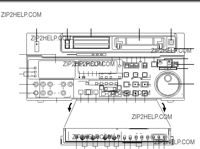
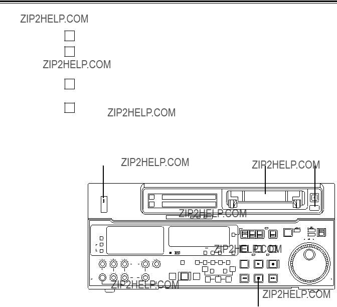
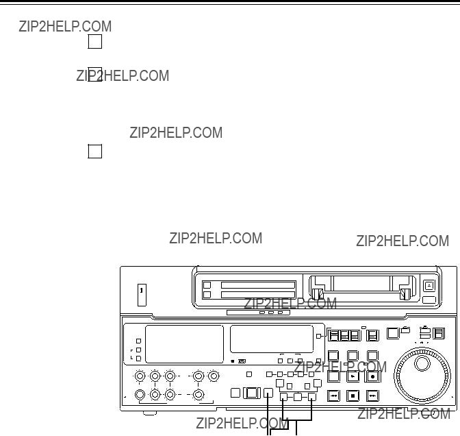
Controls and their functions
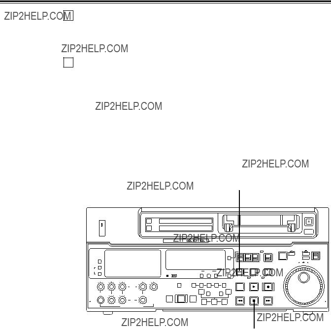
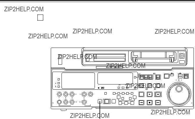
Front panel
$9 %0 %1 %2%4%3 %5 %6 %7 %8 %9 ^0
<Front Panel Top Section>
qPOWER switch
When the ON side is pressed, the power is switched on, and the audio level and video level meters, counter display and INPUT SELECT display light up.
wINPUT SELECT switches
These are used to select the video and audio input signals.
<Video>
Each time the VIDEO button is pressed, the input video signal selection is switched in the order of Y PB PR, COMPOSITE, SDTI (V&A), SDI and back to Y PB PR. If SDTI (V&A) is selected, both the video and audio signals will be input from SDTI.
<Audio>
Each time the AUDIO button is pressed, the input audio signal selection is switched in the order of ANALOG, AES/EBU, USER SET, SDI and back to ANALOG.
USER SET is a function for selecting two different input signals to be recorded on PCM audio signal CH1 and CH2, and it is used in tandem with the setup menu.
For instance, if USER SET is selected by INPUT SELECT and CH1=ANALOG, and CH2=DIGI are selected on the setup menu No. 710 (CH1 IN SEL), No. 711 (CH2 IN SEL) and No. 712 (DIGI IN SEL), the analog input signal and AES/EBU digital signal will be respectively recorded on channels 1 and 2 of the PCM audio signals recorded on the tape. However, when SDTI has been selected for the video input, SDTI input will be forcibly established for the audio input as well.
???6 ???

<Front Panel Top Section>
eINPUT SELECT display
The characters corresponding to the selected input signal light. When, with the exception of analog signals, the selected input signals are not available, the display flashes to alert the user.
<Video>
Y PB PR: Analog component video signal
CMPST: Analog composite video signal
SDTI (V&A): Compressed data, serial and digital video and audio signals (option)
SDI: Serial digital video signal (EBU Tech.
When BB has been selected as the setup menu No. 601 (INT BB SIG) setting, the entire display area will light up.
<Audio>
ANALOG: Analog audio signal
AES/EBU: Digital audio signal
USER SET: Selection of audio signal to be recorded
SDI: Serial digital audio signal (EBU Tech.
When ON has been selected as the setup menu No. 722 (INT SG) setting, the entire display area will light up.
rCassette insertion slot
The M cassette, L cassette and consumer cassette (S cassette) with adaptor are inserted into this slot.
Consumer cassettes can be played back only.
tEJECT button
When this is pressed, the tape is unloaded and several seconds later the cassette is automatically ejected. When the counter display indicates ???CTL???, the display is reset.
The lamp lights when the eject command is received.
yChannel condition lamps
One of these lamps lights in accordance with the error rate status. (Green???amber???red) Green: This lights when the error rates for the video and audio playback signals are both
acceptable.
Amber: This lights when the error rate for the video or audio playback signals has deteriorated.
Red: The playback picture will remain normal even when this lamp lights.
This lights when the video or audio signals are subject to rectification or interpolation.
uAUTO OFF lamp
This lights when trouble has arisen in the deck???s operation.
??? 7 ???

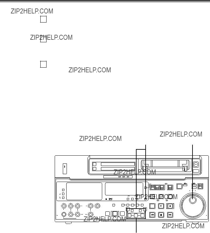
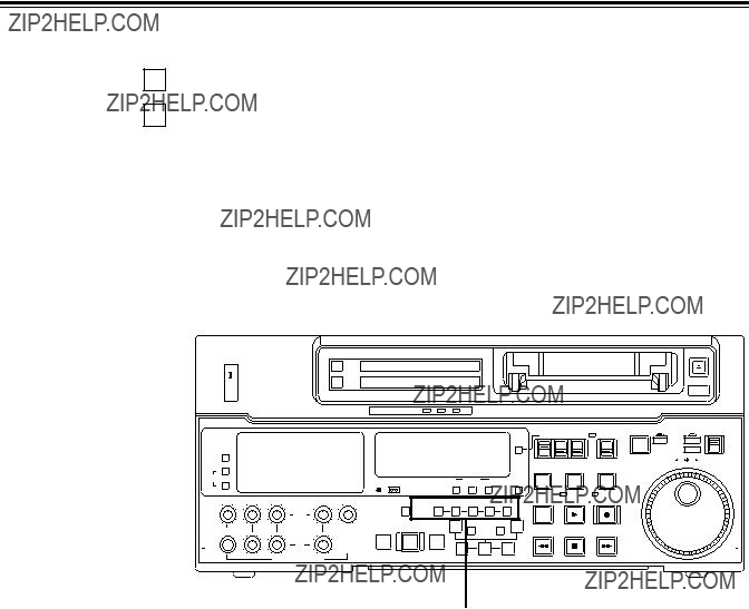
Controls and their functions (continued)
<Front Panel Center Section>
iPLAY button
Playback commences when this button is pressed.
Recording commences when the button is pressed together with the REC button; manual editing commences when it is pressed together with the EDIT button during playback. Pressing only the PLAY button during manual editing will cut out the editing and establish the playback mode.
oREC button
Recording commences when this button is pressed together with the PLAY button.
When it is pressed during playback, search, fast forward or rewind, EE mode images and audio signals can be monitored for as long as it is kept depressed.
When it is pressed in the stop mode, EE mode images and sound can be monitored. When the STOP button is pressed, the original picture and sound are restored.
!0STOP button
When this is pressed, the tape stops traveling, and if the TAPE/EE selector switch is at TAPE, still pictures can be monitored.
The drum continues to rotate even in the stop mode, and the tape remains in close contact with the drum.
If the stop mode continues for more than a certain period of time, the unit automatically switches to the standby OFF mode in order to protect the tape.
The stop mode is established immediately after a cassette has been inserted into the unit.
!1FF button*
The tape is fast forwarded when this is pressed.
!2REW button*
The tape is rewound when this is pressed.
!3EDIT button
For manual editing, press both this button and the PLAY button together during playback. When the button is pressed in the stop mode, the input mode signals selected by the ASSEMBLE or INSERT button can be monitored in the EE mode.
The original picture and sound are restored when the STOP button is pressed.
When the button is pressed during playback, search, fast forward or rewind, the input signals of the mode selected by the ASSEMBLE or INSERT button can be monitored in the EE mode for as long as the button is held down.
!4SERVO lamp
This lights when the drum servo and capstan servo have locked.
!5REC INHIBIT lamp
This lights when the REC INHIBIT switch in the front panel bottom section is at ON or when the accidental erasure prevention mode has been set for the cassette.
In this state, neither recording nor editing is possible.
*The FF/REW speed can be selected on the setup menu No. 102 (FF. REW MAX), and it is set to the same speed.
??? 8 ???

<Front Panel Center Section>
!6STAND BY button
When this is pressed, the same tension as in the regular stop mode is applied to the tape, and while the head drum continues to rotate, the button???s lamp lights to indicate that the standby ON mode is established.
In the standby OFF mode, the
When this button is pressed in the stop mode, the standby OFF mode is established, the
When this button or the STOP button is pressed in the standby OFF mode, the standby ON mode is established.
When a button other than the STOP button is pressed, the mode corresponding to the button pressed is established.
!7PLAYER/RECORDER buttons
These buttons are operated when editing operations are conducted using the unit as the recorder and a VTR equipped with an
PLAYER button: When this button is pressed, its lamp lights, and the player connected to the unit can be operated by remote control. The unit???s editing and tape transport buttons now control the player???s functions.
RECORDER button: When this button is pressed, its lamp lights, and the editing and tape transport buttons control the recorder???s (= the unit???s) functions.
!8TC/CTL switch
By pressing this switch, what appears on the counter display is changed between TC and CTL.
When TC is selected, either the TC or UB value is displayed depending on the position selected by the TC/UB switch.
!9TC/UB switch
This selector switch determines whether the value of TC or UB appears on the counter display when the TC/CTL switch has been set to TC.
@0INT/EXT switch
INT: For using the
EXT: For using the time external code which is input from the time code input connector or the video signal VITC. The selection is set at the setup menu No. 505 (EXT TC SEL).
@1TAPE/EE switch <In the stop mode>
TAPE: For outputting the signals played back from the tape.
EE:For outputting the input signals selected by the INPUT SELECT switch.
Select NORMAL or THRU as the setup menu No. 116 (EE MODE SEL) setting. In either case, use the switch for monitoring purposes.
<In the editing*/recording mode>
TAPE: For outputting the simultaneous playback signals.
EE:For outputting the input signals selected by the INPUT SELECT switch.
*The SETUP menu No. 308 (CONFI EDIT) setting is required.
??? 9 ???

Controls and their functions (continued)
<Front Panel Center Section>
@2REMOTE/LOCAL switch
This switch is set when the unit is to be controlled from an external source using the REMOTE connector,
REMOTE: Set to this position when controlling the unit by a device connected using the
LOCAL: Set to this position when controlling the unit using the controls on its own operation panel.
@3REMOTE lamp
This lights when the REMOTE/LOCAL switch has been set to the REMOTE position.
@4Search button
This button is pressed to establish the search mode.
When the search dial is set to the shuttle mode and turned to a particular position, and this button is pressed, playback commences at the speed set by the search dial.
@5JOG/SHTL/SLOW lamps
These indicate the present status of the search dial and SHTL/SLOW switch.
JOG: This lights when the unit is in the JOG mode.
SHTL: This lights when the unit is in the SHTL mode.
SLOW: This lights when the unit is in the VAR (variable) mode.
@6SHTL/SLOW switch
This selector switch is set when the search dial is used for SHTL or SLOW applications.
@7REV/STILL/FWD lamps
One of these lamps lights depending on the operation of the search dial.
REV: This lights when the dial is turned counterclockwise and the tape travels in the REV direction provided that the lamp in the search button has lighted.
STILL: This lights in the JOG mode while the dial is kept stationary, and the tape stops traveling provided that the lamp in the search button has lighted.
It lights in the SHTL mode provided that the dial is at the STILL position.
FWD: This lights when the dial is turned clockwise, and the tape travels in the FWD direction provided that the lamp in the search button has lighted.
@8Search dial
This is used to search for the edit points.
Each time it is pressed, the mode is alternately set to shuttle or jog, and one of the JOG, SHTL and SLOW lamps lights. When the power has been turned on, the dial will not function until it has first returned to the STILL position.
Shuttle mode: When the dial is turned and stopped at a particular position while the SHTL/SLOW switch is at SHTL, the tape can be played back at the speed corresponding to the dial???s rotary angle position. A still picture appears at the dial???s center position.
When the dial is turned all the way counterclockwise with the SHTL/ SLOW switch at SLOW, the tape speed is set to
Jog mode: The dial clickstops are cleared, and the tape is played back at the speed corresponding to the speed at which the dial is turned. The maximum speed can be selected using the setup menu No. 320 (JOG FWD MAX) and No. 321 (JOG REV MAX) settings.
??? 10 ???
<Front Panel Center Section>
@9PREROLL button
This is used for feeding and cueing the tape for manual editing. When it is pressed, the tape travels to the preroll point where it stops.
The preroll time can be set on the setup menu No. 000
When this button is pressed while the IN or OUT button is held down, the tape can be cued to the IN or OUT point entered.
When the AUTO ENTRY on the setup menu No. 311 is set to ???ENA???, IN point has been entered at the point where the PREROLL button is pressed even if the IN point has not been entered.
#0AUTO EDIT button
Automatic editing is executed when this is pressed after an edit point has been entered. When the AUTO EDIT button is pressed though the IN point has not been entered, automatic editing is executed using the point at which the button was pressed as the IN point.
#1PREVIEW/REVIEW buttons
PREVIEW: When this is pressed after an edit point has been entered, the tape travels, editing is not performed, and the rehearsal can be activated on the screen connected to the recorder.
If it is pressed when the IN point has not been entered, the point at which the button was pressed is entered as the IN point, and preview is executed accordingly.
REVIEW: If this is pressed after a block has been edited, the now edited block can be played back and monitored on the screen connected to the recorder.
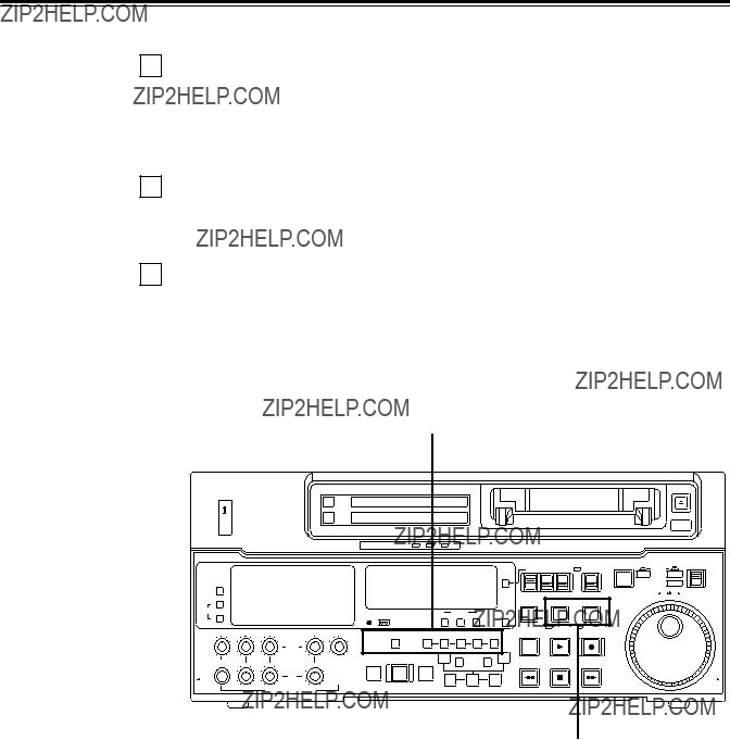
#2IN (A IN)/SET/OUT (A OUT) buttons
When the SET button is pressed while the IN (A IN) or OUT (A OUT) button is held down, the IN or OUT point is entered.
The A IN and A OUT buttons are used to enter audio IN and OUT points which are different from the corresponding video points for audio split editing.
While an IN or OUT point is being entered, the lamp in the IN or OUT button correspond- ing to the point being entered lights.
When this button is pressed after a point has been entered, the IN or OUT point value appears on the counter display. When the IN or OUT button is pressed together with the RESET button, the IN or OUT point entry is cleared.
#3TRIM buttons
These buttons are used to trim IN or OUT point finely.
When the ???+??? or
#4ASSEMBLE button
This is pressed for assemble editing.
The button is
#5INSERT buttons
Press one of these five buttons to select the input signals to be edited during insert editing. The buttons are
#6Counter display
This displays the TC and CTL count values,
??? 11 ???

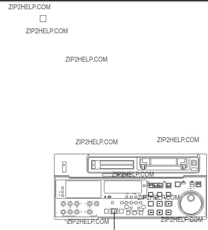
Controls and their functions (continued)
<Front Panel Center Section>
#7Time code buttons
These are used to set the TC or UB value.
SHIFT: When setting the TC or UB value, first press this button to stop the data running. Change the digit now flashing on the display.
Each time the button is pressed, the flashing moves to the right by one digit, and when it reaches the
When it is kept depressed, the flashing moves consecutively.
ADJ: This is used to change the numeral of the digit now flashing on the display. When the button is pressed once, the number is incremented by 1, and when it is kept depressed, the number is incremented consecutively.
START: This enters the data which has been changed by the SHIFT and ADJ buttons. Also, Pressing this button when the TC or UB value are not set enables the TCG or UBG setting values to be confirmed.
RESET: When this button is pressed in the CTL mode, the display is reset to ???00:00:00:00???. In the CTL mode, the entered edit points are cleared.
In the TC/UB mode, the generator is reset when the button is pressed together with the SHIFT button.
#8Warning lamp
This lights to warn the operator of a particular item.
#9Cassette insertion display lamp
This lights when a cassette has been inserted into the unit.
$0Consumer cassette insertion display lamp
This lights when a cassette recorded on a consumer DV device has been inserted.
$1SCH lamp
This lights when the SCH of the external sync signal is within a specific range.
$2CF lamp
This lights when the color framing is locked.
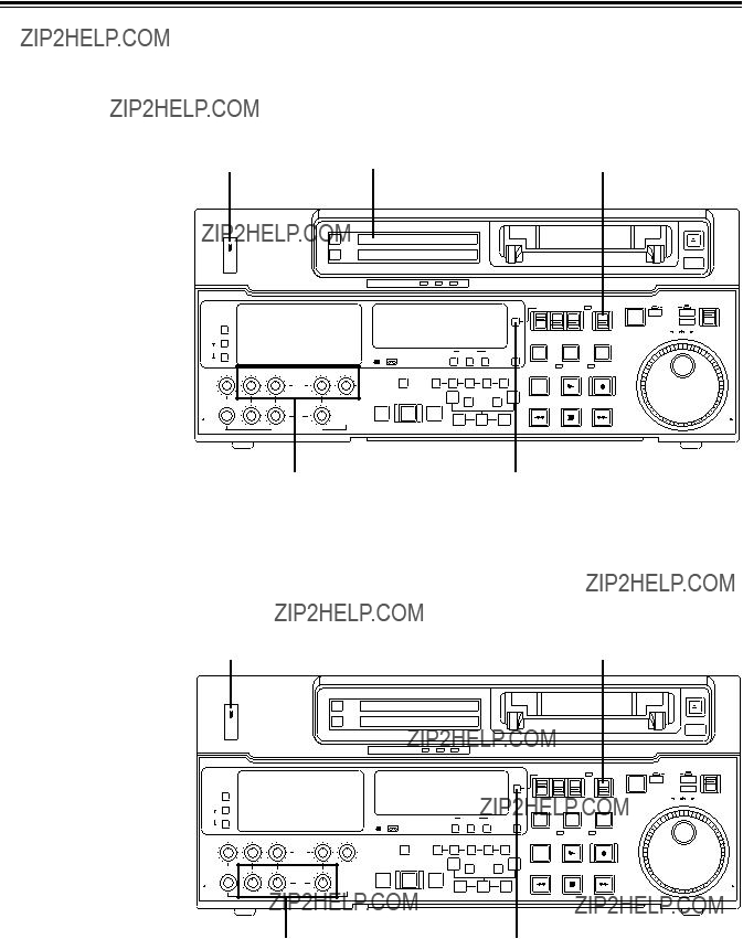
$3Level meters
These indicate the PCM audio signal CH1/CH2, CUE track signal and video signal levels. The audio signal indicates the output signal levels.
The video signal indicates the input signal levels.
$4Input/output level controls*
These are used to adjust the recording and playback levels of the PCM audio signal CH1/ CH2 and CUE track signals and the recording level of the composite video signals.
Each control located on the upper level is for adjusting the recording level, and each control located on the lower level is for adjusting the playback level.
These are ???pull for variable??? controls which means that they enable adjustment only when they have been pulled up. The signals levels are set to the unity value (preset value) when the controls have been pushed down.
$5Headphones jack
The sound being recorded, played back or edited can be monitored on stereo headphones when they are connected to this jack.
*The input levels are always fixed (at
???12 ???

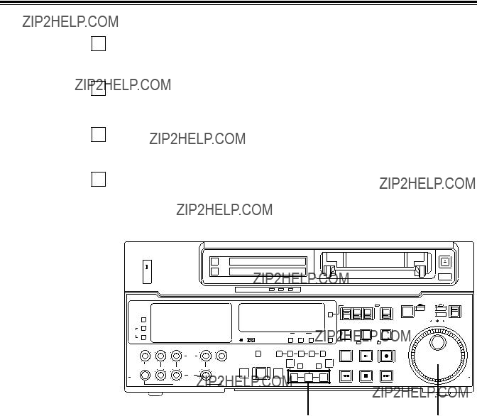
<Front Panel Center Section>
$6Volume control
This is used to adjust the headphones volume and the monitor output volume.
Whether the headphones output and monitor output volumes are to be linked or kept separate can be set on the setup menu No. 708 (MONI OUT). (Note that the headphones output volume is normally linked.)
When the volumes are kept separate, the monitor output is set to the unity value (preset value).
$7MONITOR SELECT switches
These are used to select the audio signals output to the monitor L/R channels.
Each time the ???L??? button is pressed, the signals output to the monitor L channel are selected in turn in the following order: CH1, CH2, CUE and back to CH1.
Each time the ???R??? button is pressed, the signals output to the monitor R channel are selected in turn in the following order: CH1, CH2, CUE and back to CH1.
The L or R lamp on the level meter display lights to indicate which signal is now being selected. (When the unit is set to ???AUTO 1??? or ???AUTO 2??? in No. 713 (MONI CH SEL) on the setup menu, then the display will change according to the monitor output.)
$8METER (FULL/FINE) selector switch
This switch is used to select the scale unit display mode for the audio level meters.
FULL mode: Standard scale units (ranging from
FINE mode: The scale is divided up into 0.5 dB increments.
??? 13 ???

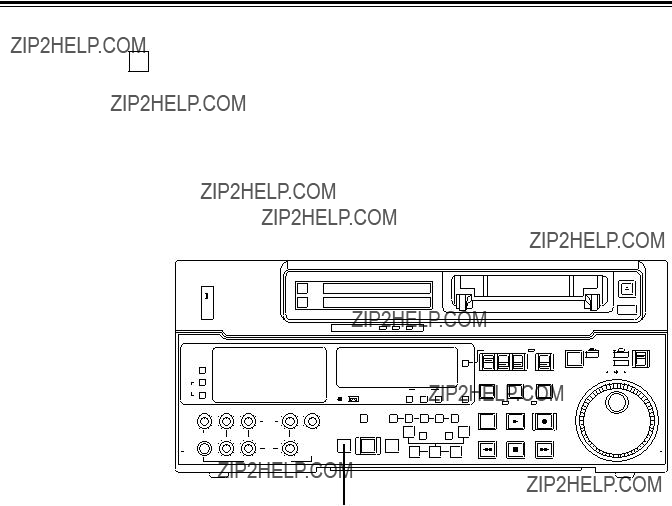
Controls and their functions (continued)
<Front Panel Bottom Section>
$9ENCODER CONTROL switch
This selects whether the adjustments to the video output signals are to be performed by the unit or by an external encoder/remote controller.
REMOTE: The adjustments to the video output signals are performed by the external encoder/remote controller.
LOCAL: The adjustments to the video output signals are performed by the unit.
%0VIDEO LEVEL control and switch
When the ENCODER CONTROL switch is at LOCAL, the video level can be adjusted. When it is at PRESET, the video level is set to the unity value (0 dB).
When it is at MANUAL, the video level can be adjusted using this control.
%1CHROMA LEVEL control and switch
When the ENCODER CONTROL switch is at LOCAL, the chroma level can be adjusted. When it is at PRESET, the chroma level is set to the unity value (0 dB). When it is at MANUAL, the chroma level can be adjusted using this control.
%2SET UP control and switch (Composite output only variable.)
When the ENCODER CONTROL switch is at LOCAL, the setup level can be adjusted. When it is at PRESET, the setup level is set to the unity value (0 IRE). When it is at MANUAL, the setup level can be adjusted using this control.
%3HUE control and switch (Composite output only variable.)
When the ENCODER CONTROL switch is at LOCAL, the hue can be adjusted. When it is at PRESET, the hue is set to the unity value (0??). When it is at MANUAL, the hue can be adjusted using this control.
%4CF switch
This selects whether the playback framing is to be locked in
8F/4F: The framing is locked in
2F: The framing is locked in
Switching to 8F or 4F is enabled by the SETUP menu No. 107 (CAP.LOCK) setting.
%5SYNCHRONIZE switch
This selects whether to provide phase synchronization between two decks. ON: Phase synchronization is provided.
OFF: Phase synchronization is not provided. The edit point will be off by several frames, but editing can be performed quickly.
%6TC generator switch
REGEN: When the REGEN/PRESET switch is at REGEN, the internal time code generator is synchronized with the time code which the time code reader read from the tape. Whether to set TC or UB to REGEN can be selected at the setup menu No. 503 (TCG REGEN).
PRESET: When the REGEN/PRESET switch is at PRESET, presetting is enabled by the controls on the operation panel or by remote control.
REC RUN: The time code runs only during recording when the RUN MODE switch has been set to REC. The time code runs constantly when the REGEN/PRESET switch is set to REGEN.
FREE RUN: The time code runs regardless of the operation mode as long as the power is being supplied when the RUN MODE switch has been set to FREE.
??? 14 ???

<Front Panel Bottom Section>
%7REC INHIBIT switch
This selects whether to enable or inhibit the recording on the cassette tape. ON: The recording on the cassette tape is inhibited.
The REC INHIBIT lamp on the front panel now lights.
OFF: The recording on the cassette tape is enabled provided that the cassette???s accidental erasure prevention mechanism has been set to the recording enable position.
%8MENU button
When this is pressed, the setup menu appears on the TV monitor using VIDEO OUT 3 connector, and the setup menu No. appears on the display.
When it is pressed again, the setup menu setting mode is exited and the original operating mode is restored.
%9SET button
When this is pressed, the data which has been set on the setup menu is entered. After data entry, the setup menu setting mode is exited and the original operating mode is restored.
^0DIAG button
When this is pressed, VTR information is displayed. When it is pressed again, the original display is restored.
There are two types of VTR information: ???HOURS METER??? information and ???WARNING??? information. Switching between these types is enabled by pressing the search button. Indicated on the ???HOURS METER??? screen are the
Indicated on the ???WARNING??? screen are the warnings.
??? 15 ???
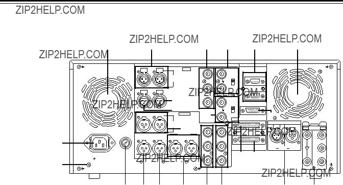
Controls and their functions (continued)
Connector area
q
w
??? 16 ???

<Connector area>
qAC IN connector
This is for connecting the unit to the power outlet using the power cord provided.
wSIGNAL GND terminal
This terminal is connected to the signa unit which is connected to the unit in order to reduce noise. It is not connected to ground for safety purposes.
eFuse holder
This contains a fuse.
rFan motor
This is for cooling the unit.
The W lamp lights when trouble has caused the fan motor to stop. If the unit is still operated in the warning status, the temperature inside the deck will rise, and when it exceeds the safety temperature, all the unit???s operations will be shut down.
tANALOG AUDIO IN connectors
These are the analog audio input connectors.
yCUE IN connector
The analog signal to be recorded on the CUE track is supplied to this connector. The audio signals from a microphone can also be recorded by selecting the
uTIME CODE IN connector
This is the connector for recording the external time code on the tape.
iANALOG COMPONENT VIDEO IN connector
The analog component video signal is supplied to this connector.
oANALOG COMPOSITE VIDEO IN connectors and 75?? termination switch
The analog composite video signal is supplied to these two connectors which are connected in a
!0REF VIDEO IN connectors and 75?? termination switch
These are the input connectors for the reference video signals. When the termination is required, set the switch to ON.
!1ANALOG AUDIO OUT connectors
The analog audio signals are output from these connectors.
!2TIME CODE OUT connector
The playback time code is output from this connector during playback.
During recording, the time code generated by the internal time code generator is output.
!3CUE OUT connector
The analog signal recorded on the CUE track is output from this connector.
!4MONITOR OUT connector
During playback, the playback signals from the CUE track or PCM audio signal CH1/CH2 are output from this connector.
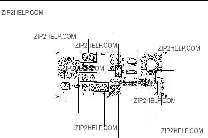
??? 17 ???

Controls and their functions (continued)
<Connector area>
!5ANALOG COMPONENT VIDEO OUT connector
The analog component video signal is output from this connector.
!6ANALOG COMPOSITE VIDEO OUT connectors
The analog composite video signals are output from these connectors.
The video signal with signals superimposed on it can be output from the VIDEO OUT3 connector.
The superimpose function can be set ON or OFF on the setup menu No. 006 (SUPER).
!7DIGITAL AUDIO IN/OUT connector
This I/O connector is for digital audio signals which comply with the AES/EBU standard.
!8SERIAL DIGITAL COMPONENT AUDIO/VIDEO IN/OUT connector (optional
This I/O connector is for digital component audio and video signals which comply with the EBU Tech.
The connectors are known by different names when the
!9Remote control connectors
The unit can be controlled from an external source by connecting the unit with another unit or an external controller.
There are two remote control connectors, one for IN/OUT uses and the other for OUT uses.
IN/OUT: For connection with an external controller. For connection with
OUT: For connection with parallel running operations.
@0ENCODER REMOTE connector
The external encoder/controller is hooked up to this connector when the video output signal and other settings are to be adjusted from an external source.
@2PARALLEL REMOTE connector
This is used when operating the unit from an external source.
??? 18 ???
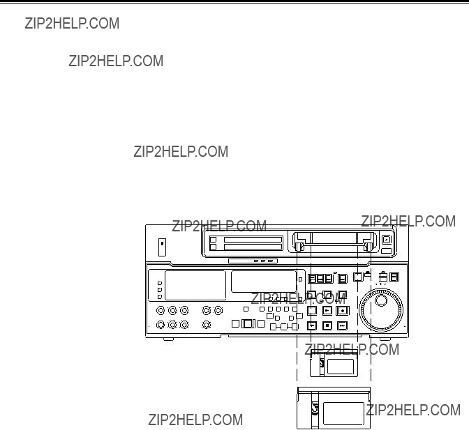
Connections when one unit is used
Set the CONTROL switch on the front panel to LOCAL.
Digital audio
input connector Digital audio/video output connectors (option)
Analog audio output
connectorsActive through output connector (option)
Video monitor output connectors (composite ???3, component)
??? 19 ???
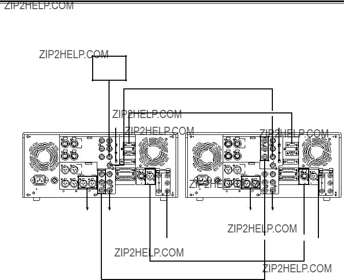
Connections when 2 units are used (deck to deck)
(Digital audio)
Analog video signal (component)
??? 20 ???
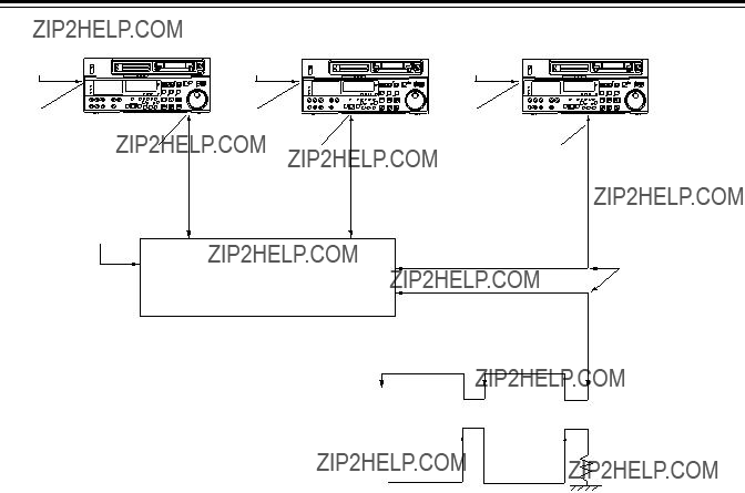
Connections with editing controller
Recorder
AV monitor
Video monitor signals
Audio monitor signals
<Note>
When an editing controller made by CMX is used, support must be provided at the editing controller side.
??? 21 ???
Connections for adjusting video output (encoder output) signals
q Supply the external reference signal from a sync signal generator to the units.
wUse the composite connectors for the video signals.
REF (BB)
??? 22 ???
Tapes
Align the cassette with the center of the insertion slot and push it in gently. The cassette tape is loaded automatically.
M cassette
L cassette
<Note>
For
<Cautions when playing back consumer DV tapes and DVCAM tapes>
???Consumer DV tapes and DVCAM tapes can be used for playback only.
???Consumer DV tapes which have been recorded in the LP mode cannot be played back.
???When materials which have been recorded on consumer DV tapes or DVCAM tapes are to be edited, record them onto a DVCPRO tape or tape of any other broadcasting VTR for use.
???Recordings cannot be made on consumer DV tapes and DVCAM tapes: this means that all functions related to recording, REC operation, editing selection and execution, TAPE/EE switching and other such operations are prohibited.
???The maximum transport speed for consumer DV tapes and DVCAM tapes is 32 times the normal tape speed.
???The maximum time for the STILL TIMER when consumer DV tapes or DVCAM tapes are used is set to 10 seconds, and the total STEP FWD time when the machine has been left standing in the STILL status is set to 1 minute.
???
???In order to protect your tapes, it is recommended that repeated
???Finally, check out the cautionary items for setup menu item No. 108 ???FORMAT SEL???.
???23 ???
Switching on the power/inserting the cassette
Before starting to operate the unit, check whether the equipment has been connected properly.
1
2
Turn on the power.
Check that the AUTO OFF lamp is off.
When condensation has formed or some other trouble has occurred, the AUTO OFF lamp lights, and all operations are disabled.
3
4
Insert the cassette tape.
Insert the tape at its proper position without force.
Check that the STOP lamp is on.
When the tape is inserted, the cylinder rotates automatically, the tape is loaded and the unit goes into the stop mode. The EJECT lamp goes off.
4
??? 24 ???
STOP/STAND BY mode
1
2
When the STOP button is pressed, the unit goes into the stop mode. The STOP lamp lights and the tape stops traveling.
???In order to protect the tape, the unit goes into the standby OFF mode after the time set by setup menu No. 400 (STILL TIMER) has elapsed. When the STOP, REW, FF or PLAY button is pressed, the unit will go into the appropriate mode.
When the STAND BY button is pressed, the unit goes into the standby ON/OFF mode. When the button???s lamp is lighted, the unit is in the standby ON mode.
When the button is pressed during the stop mode, the unit goes into the standby OFF mode and
When the button is pressed during the standby OFF mode, the unit goes to the standby ON mode.
Still Timer Setting
In order to protect the tape and VTR helical heads, it is recommended that the Still Timer be set for automatic tape protection mode in 30 seconds or under.
Page 67 indicates the settings for menu item
1
??? 25 ???

Recording
1Connect the signals to be recorded.
2Select the input signals using the INPUT SELECT switches on the front panel. The input signals corresponding to the lighted lamps have been selected.
<Notes>
???Check that the SERVO lamp is lighted during recording. If it flashes or if it is off, the images played back will be disturbed.
???Only the analog composite video input signals can be adjusted. (The digital video and analog component input signals cannot be adjusted.)
???The sound and pictures to be recorded are offset from the playback pictures by 5 frames and recorded. When, for instance, recording sound at a particular timing while the playback pictures are monitored, the sound to be recorded will be recorded at a position which is offset from the playback pictures by 5 frames.
??? 26 ???

Playback
1
2
3
4
Insert the cassette tape, and place the unit in the stop mode.
Press the PLAY button.
Regular playback is now commenced.
Adjust the audio playback level.
Pull out the audio level controls and turn them clockwise or counterclockwise to adjust the levels. Normally, they are kept in the
To end playback, press the STOP button.
The VTR now goes into the stop mode.
<Note>
Check that the SERVO lamp is lighted during playback. If it flashes or if it is off, the images played back will be disturbed.
??? 27 ???

Jog/shuttle
Jog mode
1 Push the search dial to the ???in??? position. Be sure that the JOG lamp lights.
2 Rotate the search dial.
The dial???s clickstops are cleared, and the tape is played back at the speed corresponding to the speed at which the dial is turned. The maximum speed can be selected using the setup menu No. 320 (JOG FWD MAX) and No. 321 (JOG REV MAX) settings. When the dial rotation is stopped, a still picture appears. The playback picture is
3 To transfer from the jog mode to another mode, press the appropriate button.
Shuttle mode
1 Push the search dial to release it from the ???in??? position. The SHTL lamp lights, and the unit goes into the shuttle mode.
???Immediately after the power has been turned on, rotate the search dial and set it to the center position.
2 Set the SHTL/SLOW switch to SHTL or SLOW.
3
4
Rotate the search dial.
When the SHTL/SLOW switch has been set to SHTL, the playback picture speed is varied from 0 to ??60??? normal speed depending on the position of the dial. The playback picture speed can be switched to ??16???, ??32??? and ??60??? normal speed with setting menu No. 101 (SHTL MAX).
The dial???s center position is a clickstop where a still picture appears as the playback image. When the SHTL/SLOW switch has been set to SLOW, the playback picture speed is varied from
The dial???s center position is a clickstop where a still picture appears as the playback image. The playback picture is
To transfer from the shuttle mode to another mode, press the STOP button or other button.
<Note>
When the unit leaves the factory, its operation is set up so that it will be transferred to the shuttle or jog mode when the search dial is rotated. If it is inconvenient for operation to be transferred to the
Set setting menu No. 100 (SEARCH ENA) to KEY.
??? 28 ???

Manual editing
1
2
3
4
5
Select the editing mode.
ASSEMBLE: For assemble editing.
INSERT: For insert editing.
Select the editing channel.
In the case of insert editing, press the channel button corresponding to the signals to be edited, and check that its lamp is on.
Press the PLAY button.
Search for the position where the editing is to be commenced (IN point) while viewing the TV monitor, and press the PLAY and EDIT buttons together at the IN point.
Press the STOP or PLAY button at the position where editing is to be completed (OUT point) while viewing the TV monitor. The unit goes into the stop mode, and editing is completed.
<Note>
The sound and pictures to be recorded are offset from the playback pictures by 5 frames and recorded. When, for instance, recording sound at a particular timing while the playback pictures are monitored, the sound to be recorded will be recorded at a position which is offset from the playback pictures by 5 frames.
??? 29 ???

Preroll
1 Press the PREROLL button.
The VTR now performs the preroll operation.
???When the edit IN point has been entered, the tape is rewound from the edit IN point for the duration set by setting menu ???000,??? and the unit then goes into the stop mode.
???When the edit IN point has not been entered, the tape is rewound for the duration set by setting menu ???000??? from the position where the button was pressed, and the unit then goes into the stop mode.
<Notes>
???The time code or CTL signal must be continuously recorded between the edit IN point and preroll point.
???When the IN point has not been entered, whether to enter the IN point and perform preroll or to perform preroll without entering the IN point can be selected at setting menu No. 311 (AUTO ENTRY).
??? 30 ???
Automatic editing (Deck to Deck)
Editing refers to the job of using a prerecorded tape to produce a complete recording by joining together separate cuts and deleting unnecessary parts.
The basic steps taken for editing are as follows.
??? 31 ???
Automatic editing
Switch settings and adjustments
When the unit is used as the recorder:
AUTO OFF
When the unit is used as the player:
??? 32 ???
Select the editing mode
1
2
3
Select the editing mode.
For assemble editing, press the ASSEMBLE button. For insert editing, press the INSERT button.
ASSEMBLE: The assemble editing mode (in which cuts are joined together) is established.
INSERT: The insert editing mode (in which cuts are inserted) is established.
Select the editing channel.
With assemble editing, the ASSEMBLE lamp lights.
With insert editing, press the button of the channel whose signals are to be edited and lights its lamp.
Select the VTR to be operated (this setting is performed when editing with 2 VTRs). Press the PLAYER or RECORDER button to select the VTR.
PLAYER: Press this button to operate the player VTR and enter the edit points.
RECORDER: Press this button to operate the recorder VTR (this unit) and enter the edit points.
1, 2
??? 33 ???
Automatic editing
Entering the edit points
1
2
3
4
Search for the edit IN point by performing the jog or shuttle operation. Establish the still picture mode at the desired position.
Refer to page 28 for details on the jog/shuttle operations.
Press the SET button while holding down the IN button. The edit IN point is now entered.
The edit IN point value now appears on the display.
Search for the edit OUT point by performing the jog or shuttle operation. Establish the still picture mode at the desired position.
Refer to page 28 for details on the jog/shuttle operations.
Press the SET button while holding down the OUT button. The edit OUT point is now entered.
The edit OUT point value now appears on the display.
2, 41, 3
Match frame processing function
When using two VTRs for editing, a total of four edit
Negative duration function
This function is used by combining setup menu No. 301 (IN/OUT DEL) and No. 302 (NEGA FLASH) described on page 63.
??? 34 ???
Checking the edit points
1
2
3
Press the IN (or OUT) button to check the edit point.
The value of the entered edit point appears on the display.
Press the PREROLL button while holding down the IN (or OUT) button to check the image at the edit point.
The tape is cued at the edit IN (or OUT) point, and the still picture mode at that point is displayed.
???The EE mode is established if the TAPE/EE switch has been set to the ???EE??? position when ???STOP??? has been selected for the setup menu No. 313 (AFTER
Press and hold down the IN and OUT buttons together to check the edit duration. The duration time appears on the display.
Calculating the duration
???When both edit points have been set, the duration between the two edit points.
???When only one edit point has been set, the duration between the set data and the current tape address.
???When neither edit point has been set, the duration of the previously edited interval.
2 1, 3
??? 35 ???
Automatic editing
Modifying the edit points
1
2
3
Search for the new edit point by performing the jog or shuttle operation, and press the IN (or OUT) and SET buttons together to
Modifying the edit point in frame units (trim function)
Press the TRIM button while holding down the IN (or OUT) button.
The edit point is put ahead by 1 frame each time the + button is pressed. The edit point is put back by 1 frame each time the ??? button is pressed.
Resetting the edit points
??? Press the RESET button.
??? Press the RESET button while holding down the IN (or OUT) button.
<Notes>
???Edit points can be reset only in the CTL mode.
???An edit OUT point can be reset even while editing is in progress.
???The IN and OUT points are automatically reset during the eject mode.
2
??? 36 ???
Preview
1
After the edit points have been entered, press the PREVIEW button. Normal preview is now performed.
<Notes>
???If the edit IN point has not been entered, the position where the PREVIEW button was pressed will be entered at the edit IN point.
???To stop the preview at any time, press the STOP button.
???If the PREVIEW button is pressed again while preview is in progress after the IN point, preview will start again from the beginning.
???When the edit OUT point is reached, the unit automatically goes into the stop mode.
1
??? 37 ???
Automatic editing
Executing automatic editing
1 Press the AUTO EDIT button. Automatic editing is now performed.
???To stop the editing at any time, press the STOP button.
???When the edit OUT point is reached, the unit goes into the stop mode after postrolling.
Postroll
With assemble editing, editing continues for approx. 2 seconds even after the edit OUT point has been passed, the tape is rewound to the OUT point, and the unit goes into the stop mode.
With insert editing, the unit goes into the play mode after the edit OUT point has been passed, the tape is rewound to the OUT point, and the unit goes into the stop mode.
Retry function
If the AUTO EDIT button is pressed again after the STOP button has been pressed to stop the editing, editing will start again from the beginning.
Auto tag editing
If the AUTO EDIT button is pressed when the next edit point has not yet been entered upon completion of editing, the previous edit OUT point will be entered as the IN point, and editing is performed accordingly.
To release the auto tag mode, press one of the tape transport buttons (PLAY, etc.).
<Note>
The entered points are automatically cleared after editing is executed. However, the previous editing points can be recalled by pressing the TRIM+ (or
1
??? 38 ???
Review
1
Upon completion of the editing, press the REVIEW button.
The review is started in the recorder.
???To stop the review at any time, press the STOP button.
???When the edit OUT point is reached, the unit goes into the stop mode after postrolling.
1
??? 39 ???
Split editing
Split editing refers to editing where the editing channels are switched while insert editing is in progress.
1
2
Perform insert editing.
Switch the editing channel.
When, for instance, sound from AUDIO CH2 is to be additionally inserted during video channel insert editing:
The lamp in the button lights and the AUDIO CH2 sound is insert edited.
2
??? 40 ???
Audio split editing
The video edit points and audio edit points can be entered separately, and they can be offset from each other and edited.
Audio edit points can be entered, deleted and revised only when the insert editing mode has been selected. After the edit points have been entered, follow the same operating procedure as that for insert editing.
??? Entering the edit points
Video IN point: Video OUT point: Audio IN point: Audio OUT point:
Press the SET button while holding down the IN button. Press the SET button while holding down the OUT button. Press the SET button while holding down the A IN button. Press the SET button while holding down the A OUT button.
??? Deleting the edit points
Video IN point: Video OUT point: Audio IN point: Audio OUT point:
Press the RESET button while holding down the IN button. Press the RESET button while holding down the OUT button. Press the RESET button while holding down the A IN button. Press the RESET button while holding down the A OUT button.
??? Modifying the edit points
Video IN point: Video OUT point: Audio IN point: Audio OUT point:
Press the TRIM+ or TRIM??? button while holding down the IN button. Press the TRIM+ or TRIM??? button while holding down the OUT button. Press the TRIM+ or TRIM??? button while holding down the A IN button. Press the TRIM+ or TRIM??? button while holding down the A OUT button.
??? Indicating audio split editing
When the audio edit points are entered, ??? ??? ??? appears superimposed on the front panel and TV monitor to denote audio split editing.
TCR 00:00:00:00
???AUTO EDIT
This denotes audio split editing.
A IN A OUT
Button Button
??? 41 ???

Audio split editing
??? Displaying the audio split edit points
The edit points are displayed on the front panel as shown below. (The figure shows an audio IN point.)
Operations
Video IN point: Press the IN button.
Video OUT point: Press the OUT button.
Audio IN point: Press the A IN button.
Audio OUT point: Press the A OUT button.
AIN 00:00:04:07
IN, OUT, AIN (audio IN point), AOUT (audio OUT point)
<Note>
If the editing mode is switched to assemble editing after audio edit points have been entered, these points will be deleted.
??? Cueing up the tape to the edit points
Press the PREROLL button while holding down the IN button. Press the PREROLL button while holding down the OUT button.
Press the PREROLL button while holding down the A IN button.
Press the PREROLL button while holding down the A OUT button.
??? Duration display
The duration can be displayed on the front panel only.
Duration from video IN point to OUT point: Press the IN and OUT buttons simultaneous- ly.
Duration from audio IN point to OUT point: Press the A IN and A OUT buttons simulta- neously.
Match frame processing mechanism
When two VTRs are used for audio split editing operations, there will be a total of eight edit points: two pairs of video IN and OUT points, one for the player and the other for the recorder, and two pairs of audio IN and OUT points, one for the player and the other for the recorder. Since the remaining three points are automatically calculated when five of these eight edit points are entered, up to five edit points can be entered.
<Note>
If, during audio split editing, only the video OUT point (or audio OUT point) is entered and automatic editing is executed without the audio IN point (or video IN point) having been entered, editing will continue until the audio OUT point (or video OUT point) is entered or the STOP button is pressed to suspend operation.
??? 42 ???
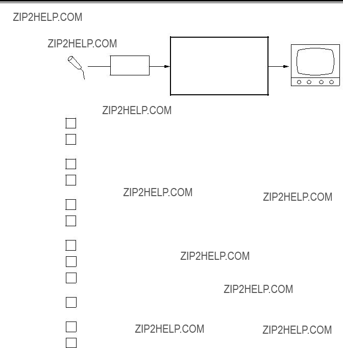
Operating procedure 1
MIC
AMP
Microphone
1
2
Select INT_VO as the setup menu No. 322 (AUD MEM MODE) setting.
Select the same setting for the channel (CH1 or CH2) on which the sound is to be recorded and for the setup menu No. 323 (AUD MEM CH) channel.
3
4
5
6
7
8
9
Insert the cassette tape for which the
Press the insert button for the channel (CH1 or CH2) on which the sound is to be recorded and ensure that its lamp lights.
Press the PLAY button.
Search the position (IN point) where
Press the IN and SET buttons simultaneously at the IN point.
Input the audio signals to be recorded to the channel which was selected in step 2.
Search the position (OUT point) where
10 Press the A OUT and SET buttons simultaneously at the OUT point. The audio signals to be recorded are stored in the memory.
11
12
Press the STOP button.
Press the AUTO EDIT button to proceed with editing. The audio signals stored in the memory are recorded from the memory onto the cassette tape.
<Note>
The audio signals can be previewed prior to editing by pressing the PREVIEW button while the SET button is held down before the AUTO EDIT button is pressed.
??? 43 ???

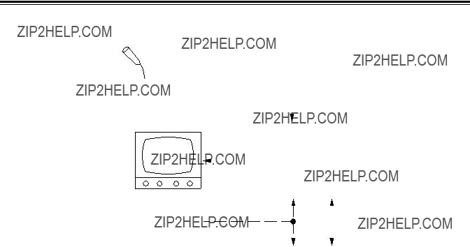
Operating procedure 2
1
2
Select INT_VO as the setup menu No. 322 (AUD MEM MODE) setting.
Select the same setting for the channel (CH1 or CH2) on which the sound is to be recorded and for the setup menu No. 323 (AUD MEM CH) channel.
3
4
5
6
7
Insert the cassette tape for which the
Press the insert button for the channel (CH1 or CH2) on which the sound is to be recorded and ensure that its lamp lights.
Enter the IN and OUT points of the positions where
Press the PREVIEW button.
While watching the TV monitor, input the audio signals to be recorded between the IN point and OUT point into the channel which was selected in step 2. The audio signals to be recorded are stored in the memory.
8 Press the AUTO EDIT button to proceed with editing. The audio signals stored in the memory are recorded from the memory onto the cassette tape.
<Note>
The audio signals can be previewed prior to editing by pressing the PREVIEW button while the SET button is held down before the AUTO EDIT button is pressed.
T???R 00:00:00:00
m STOP
 ???m??? indicates the edit mode in which the internal memory is used.
<Notes> Memory capacity
???Up to 20 seconds of sound can be stored in the unit???s internal memory. It should be borne in mind that even if an attempt is made to store more than 20 seconds of sound in the memory, all the audio signals in excess of the memory???s
???When INT_VO or INT_X, which is performed using the internal memory in the setup menu No. 322 (AUD MEM MODE) setting, ???m??? appears on the front panel and is superimposed onto the TV monitor display to indicate that the editing mode using the internal memory is now being used.
??? 44 ???
For operation with an editing controller
<Note>
For further details on the
??? 45 ???
Audio cross channel editing (internal)
Example: To record
??? Connections
PLAYER RECORDER
EDITING
CONTROLLER
Ref
1
2
3
Select INT_X as the setup menu No. 322 (AUD MEM MODE) setting.
Select CH2 as the setup menu No. 323 (AUD MEM CH) setting.
Select the audio CH1 and CH2 in the insert editing.
<Note>
Select the video as well if the video signals are also going to be edited.
??? 46 ???

4
5
6
7
Enter the edit points of the first event on the player???s tape.
Enter the edit points of the first event on the recorder???s tape.
Operate the mixer in such a way that the player???s audio output signals are output from the mixer???s CH1 OUT and CH2 OUT connectors. (The same audio signals will be delivered through CH1 and CH2 of the mixer.)
Press the AUTO EDIT button. The first event is now recorded on the recorder???s tape. (See Fig. 1.)
The last 20 seconds (which is the capacity of the memory) of the audio signals before the OUT point are now saved in the memory.
8 Release the insert button for CH1 so that only the insert button for CH2 is engaged.
<Note>
Select the video as well if the video signals are also going to be edited.
9
10
Enter the edit point of the next event on the player???s tape.
Enter the edit point of the next event on the recorder???s tape.
<Note>
The IN point must be set up to 20 seconds (more than the cross fading duration) before the previous edit OUT point.
11 Operate the mixer in such a way that the player???s audio output signals are output from the mixer???s CH1 OUT connectors and that the recorder???s (this unit) CH1 OUT audio signals are output from the mixer???s CH2 OUT connectors. [The recorder???s (this unit) CH1 OUT signals are the audio signals supplied from the internal memory.]
12
13
Press the AUTO EDIT button.
Operate the mixer starting at the IN point, and change the mixer???s CH2 OUT signals gradually from the recorder???s CH1 OUT audio signals into the player???s audio output signals for the mixer???s CH2 OUT connectors. (Cross fading)
14 Press the CH1 insert button after the mixer???s CH2 output signals have been changed into the player???s audio output signals. The STOP mode is established at the OUT point, and the last 20 seconds (which is the capacity of the memory) of the audio signals before the OUT point are now saved in the memory. (See Fig. 2.)
15 To continue editing, repeat steps 8 to 14.
<Notes>
Before attempting to perform
1.Select either AMU_X or AMU_VO as the setup menu No. 322 (AUD MEM MODE) setting.
2.For audio cross channel editing, set the channel on which the signals are to be recorded on setup menu No. 323 (AUD MEM CH).
3.Proceed with operation, using the
???47 ???

V blanking data recording/playback
??? Additional line recording/playback function
???Select the mode for recording signals in additional lines using setup menu item No. 800 (ADD LINE).
Off: No signals are recorded in additional lines.
YC422: The input signals are recorded in 1 line in the 422 mode.
YC411: The input signals are recorded in 1 line in the 411 mode.
Y1_B/W: The input signals are recorded in 1 line in their original form as the luminance signal.
Y1_PBF: The input signals are separated into the Y (luminance) and C (chrominance) signals, and only the Y signal is recorded in 1 line.
C1: The input signals are separated into the Y (luminance) and C (chrominance) signals, and only the C signal is recorded in 1 line.
Y2_B/W: The input signals are recorded in 2 lines in their original form as the luminance signal.
Y2_PBF: The input signals are separated into the Y (luminance) and C (chrominance) signals, and only the Y signal is recorded in 2 lines.
C2: The input signals are separated into the Y (luminance) and C (chrominance) signals, and only the C signal is recorded in 2 lines.
???Select the additional lines for recording on the
???The number of lines in which the teletext signals can be recorded differs depending on which mode for recording the signals in the additional lines has been selected.
??? Teletext signal recording/playback function
???Up to 28 lines per frame of the teletext signals which are input can be recorded and played back.
???The number of lines in which the signals can be recorded differs depending on the setup menu item No. 800 (ADD LINE) setting.
???Depending on the setup menu item No. 800 (ADD LINE) setting, it may not be possible to record the input teletext signals in all of the lines.
???Listed below are the numbers of lines per frame in which the signals can be recorded in each mode.
<Note>
There is some limitation to the number of lines in which signals can be recorded with the recording and playback function of the V blanking data.
??? 48 ???
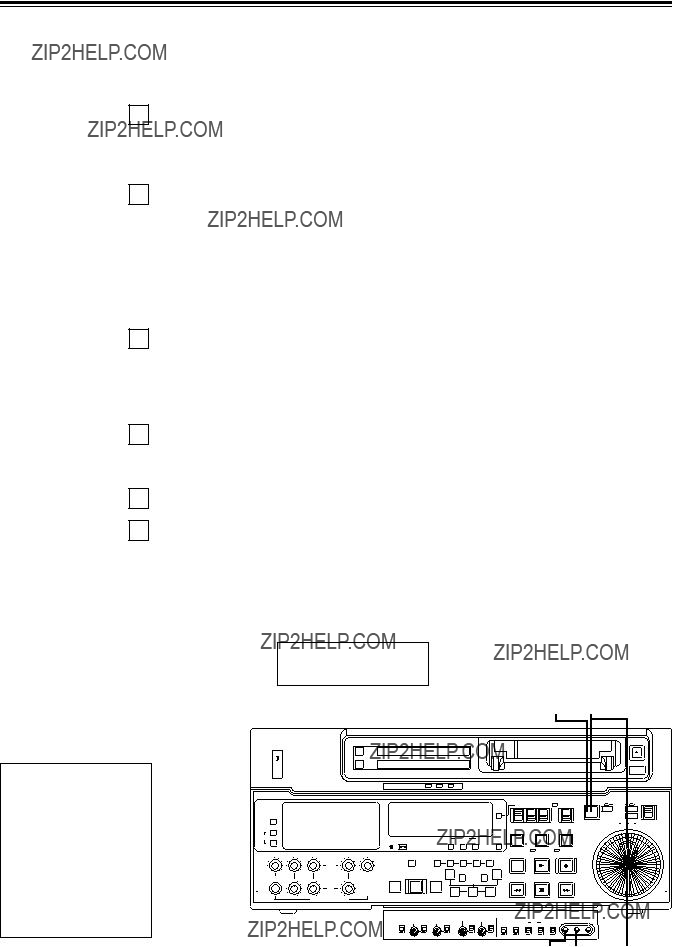
Video output (encoder output) signal adjustments
After this system has been connected, the video output signal (ENCODER OUT) must be adjusted if AB roll editing (editing using two source machines) using an editor, for instance, is to be
The adjustment procedure using this unit is outlined below.
1
2
Check the connections. (See page 22.)
Set the REMOTE/LOCAL switch @2on the front panel bottom section to the adjustment position (LOCAL).
REMOTE: For adjusting the video output signals using an external encoder remote controller.
LOCAL: For adjusting the video output signals using this unit.
3 Adjust the source machine independently.
Set the PRESET/MANUAL switches of the VIDEO LEVEL, CHROMA LEVEL, SETUP and HUE controls to PRESET.
1 Play back a cassette tape on which standard color bar signals have been recorded.
2Adjust the controls in such a way that the waveforms on the waveform monitor (WFM) and vectorscope (VSC) resemble those shown in the figures below.
ASetup level
Adjust the control to eliminate deviation.
BVideo level
Adjust this level to 100 IRE.
CChroma level and hue
Adjust the two controls in such a way that the light spot of the vector waveforms comes inside the rectangular grid mark.
B
C
A 

4 Perform the same adjustments on the source machine connected to the unit.
??? 49 ???
Setup (default settings)
The unit???s major settings are performed by making selections on menus.
The setting menus appear on the TV monitor when the TV monitor and VIDEO OUT 3 connector in the unit???s connector area are hooked up.
Changing the settings
1 Press the MENU button.
The setup menu appears on the TV monitor and setup menu No. appears on the counter display. (If the setup has already been performed, the screen showing the changes made last will appear.)
2 Rotate the search dial and select the item to be set.
The cursor ( ??? ) on the menu screen moves and the item No. on the display flashes.
???When the dial is rotated clockwise, the item No. is incremented from 001???002??? 003???004 and so on; when it is rotated counterclockwise, the item No. is decremented.
???The search dial should be used in jog mode if at all possible.
???Hold down the PLAY button and press the FF (next major item) or REW (previous major item) buttons to select the menu by major item.
3 While holding down the search button, rotate the search dial at the position where the change is to be made.
The setting No. now flashes.
When the dial is rotated clockwise, the setting value is incremented; when it is rotated counterclockwise, it is decremented.
4
5
6
Release the search button when the setting is completed. The setting value on the menu screen and display flashes.
??? During the SHTL mode, the item moves if the search dial is not at the STILL position.
Repeat steps 2 through 4 to change another item.
Press the SET button.
The changes are now stored in the memory.
???To return the items to the settings established before the changes were made, press the MENU button.
To return the setup settings to the factory (default) settings, press the RESET button while the menu is displayed. The following message will now appear:
YES<PLAY>/NO<STOP>
When the PLAY button is pressed, the factory settings are restored.
4 3
<Note>
Setup (setting) menus
This unit can store up to 5 user files (user 1 to user 5) containing different menu settings, and these files can be selected and used.
Changing the file
1
2
Press the MENU button.
Hold down the STAND BY button and press the FF button to switch to the next user file. Hold down the STAND BY button and press the REW button to switch to the previous user file.
FF
USER FILE
Each user file contains the following items.
??? BASIC
??? OPERATION
??? INTERFACE
??? EDIT
??? TAPE PROTECT
??? TIME CODE
??? VIDEO
??? AUDIO
??? V BLANK
??? MENU
3 Repeat the operation in step 2 to select the user file to be used and press the SET button. The user file is changed and stored in the memory.
<Note>
SYSTEM menu items are not included in user files 1 to 5.
Therefore, after selecting the user file, switch to the SYSTEM file and set the SYSTEM menu items.
??? 51 ???

Setup menus
Lock mode can be set to protect the settings in the system files and user files (USER2 ??? USER5). Settings can no longer be changed when this mode is set.
To set and release the lock mode for the system files and user files use setup item No. 30 (MENU LOCK) and setup menu item No. A03 (MENU LOCK), respectively.
Setting and releasing the lock mode.
1
2
Press the MENU button.
While holding down the STAND BY button, press the REW or FF button, and select the file for which the lock mode is to be set or released.
3
4
Turn the search dial and move the cursor (???) on the menu screen to setup item No. 30 (MENU LOCK) or setup menu item No. A03 (MENU LOCK) for the system or user file.
While holding down the search button, turn the search dial and select lock mode setting or release.
To set the lock: Select the 0001 (ON) setting.
To release the lock: Select the 0000 (OFF) setting.
When the lock has been set, ???LOCKED??? flashes on the menu screen. In addition, the counter display stops flashing and lights.
5 Press the SET button. The setting is now stored in the memory.
<Notes>
???The lock mode cannot be set for the USER1 file settings.
???Even if the RESET button is pressed, the files which has been set to the lock mode cannot be reset to the factory settings.
??? 52 ???

The contents of the USER2 ??? USER5 files can be copied (loaded) into the USER1 file. In addition, the contents of the USER1 file can be copied (saved) to the USER2 ??? USER5 files.
Load or save
Load or save
USER3 Settings can be locked.
Load or save
USER4 Settings can be locked.
Load or save
USER5 Settings can be locked.
Loading a user file
1 Press the MENU button.
2 While holding down the STANDBY button, press the REW or FF button, and select USER1.
3 Turn the search dial and move the cursor ( ??? ) on the menu screen to setup item No. A00 (LOAD).
The user file number selected in step 4 is displayed in the shaded area.
6 Press the PLAY button. The settings of the user file selected in step 4 are loaded, and the USER1 menu display appears. When the STOP button is pressed, the USER1 menu display appears while the settings remain unchanged.
7
8
Turn the search dial and move the cursor ( ??? ) on the menu screen to any setup item except No. A00 (LOAD) and No. A01 (SAVE).
Press the SET button. The USER1 settings are now stored in the memory.
If the USER1 settings are not going to be stored in the memory, do not press the SET button but press the MENU button.
??? 53 ???

Setup menus
Saving a user file
1 Press the MENU button.
2 While holding down the STAND BY button, press the REW or FF button, and select USER1.
3 Turn the search dial and move the cursor ( ??? ) on the menu screen to setup item No. A01 (SAVE).
The user file number selected in step 4 is displayed in the shaded area.
6 Press the PLAY button. The contents of the USER1 file are saved in the user file which was selected in step 4 and stored in the memory. When the STOP button is pressed, the USER1 menu display appears while the settings remain unchanged.
7
8
Turn the search dial and move the cursor ( ??? ) on the menu screen to any setup item except No. A00 (LOAD) and No. A01 (SAVE).
Press the SET button. The USER1 settings are now stored in the memory.
If the USER1 settings are not going to be stored in the memory, do not press the SET button but press the MENU button.
Automatic loading of user file when the power is turned on
When the user file to be loaded is selected in advance using setup menu item No. A02 (P.ON LOAD), it can be automatically loaded into USER1 when the power is turned on.
??? 54 ???

Setup (setting) menus
SYSTEM menu
<SYSTEM>
The underline on the setting item denotes the initial setting.
??? 55 ???

Setup (setting) menus
SYSTEM menu
<SYSTEM> (continued)
The underline on the setting item denotes the initial setting.
??? 56 ???

Setup menus
USER menu
<BASIC>
The underline on the setting item denotes the initial setting.
??? 57 ???

Setup menus
USER menu
<BASIC> (continued)
The underline on the setting item denotes the initial setting.
??? 58 ???

USER menu
<OPERATION>
The underline on the setting item denotes the initial setting.
??? 59 ???

Setup menus
USER menu
<OPERATION> (continued)
The underline on the setting item denotes the initial setting.
 FWD direction
zWhen the FF button is pressed, the VTR performs the regular fast forward operation since the zero point is not located in the direction of operation.
xWhen the REW button is pressed, the PREROLL lamp lights (the SHTL lamp lights as well), the VTR proceeds with the preroll operation, and it automatically stops when it reaches the position where the counter reads ???0.???
cWhen the REW button is pressed, the VTR performs the regular rewinding operation since the zero point is not located in the direction of operation.
vWhen the FF button is pressed, the PREROLL lamp lights (the SHTL lamp lights as well), the VTR proceeds with the preroll operation, and it automatically stops when it reaches the position where the counter reads ???0.???
???60 ???
USER menu
<OPERATION> (continued)
The underline on the setting item denotes the initial setting.
??? 61 ???

Setup menus
USER menu
<INTERFACE>
The underline on the setting item denotes the initial setting.
??? 62 ???

USER menu
<EDIT>
The underline on the setting item denotes the initial setting.
??? 63 ???

Setup menus
USER menu
<EDIT> (continued)
The underline on the setting item denotes the initial setting.
??? 64 ???

USER menu
<EDIT> (continued)
The underline on the setting item denotes the initial setting.
??? 65 ???

Setup menus
USER menu
<EDIT> (continued)
The underline on the setting item denotes the initial setting.
??? 66 ???

USER menu
<TAPE PROTECT>
The underline on the setting item denotes the initial setting.
<Note>
In order to protect the tape and VTR helical heads, it is recommended that the Still Timer be set for automatic tape protection mode in 30 seconds or under.
<TIME CODE>
The underline on the setting item denotes the initial setting.
??? 67 ???

Setup menus
USER menu
<TIME CODE>
The underline on the setting item denotes the initial setting.
??? 68 ???

USER menu
<TIME CODE> (continued)
The underline on the setting item denotes the initial setting.
<VIDEO>
The underline on the setting item denotes the initial setting.
SBC (sub code data) area:
This area is separate from the video and audio data area on the helical track. The time codes complying with SMPTE/EBU standards, recording dates and times, and other tape control information are stored here. As with the conventional LTC (linear time code), the time code can be read even during rewinding or fast forwarding. It can also be read out when the tape has stopped.
VAUX (video auxiliary data) area:
This area is to be found in the video data area on the helical track. The additional information relating to the video data is stored here.
??? 69 ???

Setup menus
USER menu
<VIDEO> (continued)
The underline on the setting item denotes the initial setting.
??? 70 ???
USER menu
<AUDIO>
The underline on the setting item denotes the initial setting.
??? 71 ???

Setup menus
USER menu
<AUDIO> (continued)
The underline on the setting item denotes the initial setting.
??? 72 ???

USER menu
<AUDIO> (continued)
The underline on the setting item denotes the initial setting.
??? 73 ???

Setup menus
USER menu
<V BLANK>
The underline on the setting item denotes the initial setting.
??? 74 ???

USER menu
<V BLANK> (continued)
The underline on the setting item denotes the initial setting.
??? 75 ???

Setup menus
USER menu
<V BLANK> (continued)
The underline on the setting item denotes the initial setting.
??? 76 ???

USER menu
<MENU>
The underline on the setting item denotes the initial setting.
<Notes>
???No. A00 (LOAD), No. A01 (SAVE) and No. A02 (P.ON LOAD) are the menu items which can be set only for USER1. They are not displayed with the USER2 ??? USER5 files.
???No. A03 (MENU LOCK) is the menu item which can be set only for the USER2 ??? USER5 files. It is not displayed with USER1.
??? 77 ???

Time code/user bit
Time code
The time code is used when the time code signal generated by the time code generator (time code signal generator) is to be recorded on the tape, its values are to be read by the time code reader (time code signal reader), and the absolute position of the tape is to be displayed in increments of hours, minutes, seconds and frames.
The time code is written in the
The time code values are indicated using the display and superimpose functions.
TCR 00 : 07 : 04 : 24
 Frames
Hours Seconds
Minutes
User bit
???User bit??? refers to the
The alphanumeric characters which can be used for the user bit are the figures 0 to 9 and the letters A to F.
<Note>
Time code and user???s bit control during tape play is exercised by the data recorded in the SBC area. The data recorded in this area includes the data that appears on the display or is superimposed on the TV monitor screen and the communication data that is transferred to the editing controller.
??? 78 ???

Recording internal/external time codes
1. Setting the internal time code
1
2
3
4
Place the VTR in the stop mode.
Set the TC/CTL switch to TC.
Set the TC INT/EXT switch to INT. (Internal time code selected)
Set the REC RUN/FREE RUN switch position.
REC RUN: The time code runs at the same time as the recording proceeds.
FREE RUN: The time code runs in the same way as the time regardless of the VTR???s operation.
5
6
Set the REGEN/PRESET switch position.
REGEN: Continuity is maintained with the recorded time code before editing. (Detailed settings are also possible using the menu settings. See the menu items below.)
Setup menu No. 503 (TCG REGEN) Setup menu No. 504 (REGEN MODE)
PRESET: Recording starts from the value set with the TC SET button.
<Note>
During auto editing, REGEN will be selected by the setup menu No. 504 setting even if the switch has been set to the PRESET position.
Set the TC SET button.
Use the TC SET button to set the start number of the time code or user bit.
1Press the SHIFT button. The leftmost digit flashes.
2Press the ADJ button to change the value.
Each time the button is pressed, the number changes. The setting range is given below.
???Time code
00:00:00:00 ??? 23:59:59:29
???User bit
00 00 00 00 ??? FF FF FF FF
3Repeat steps 1 and 2 to change the value.
4When the setting of the start number is completed, press the START button. In the FREE RUN mode, the time code now starts running.
5Proceed with the recording or editing.
2.Setting the external time code (TC switch ??? EXT)
1
2
3
4
Place the VTR in the stop mode.
Set the TC/CTL switch to TC.
Set the TC INT/EXT switch to EXT. (External time code selected)
Setup menu No. 505 (EXT TC SEL) can be set as follows.
LTC: The LTC signal input to the TIME CODE IN connector (XLR) on the rear jack panel is recorded as the time code.
<Note> The LTC signal must be synchronized with the video signal. VITC: The input video signal???s VITC is recorded as the time code.
??? 79 ???
Reproducing the time code/user bit
1
2
3
4
Place the unit in the stop mode.
Set the TC/CTL button to TC.
Set the TC/UB switch to TC or UB.
TC: The time code is displayed.
UB: The user bit is displayed.
???When it is no longer possible to read the time code, it is interpolated using the CTL signal.
Press the PLAY button.
Playback now commences, and the time code appears on the display.
When setup menu No. 006 (SUPER) is ON, the time code value is superimposed onto the video signal from the VIDEO OUT 3 connector.
<Notes>
???When the time code signal cannot be read, the time code is automatically interpolated by the CTL signal.
The display appears as shown below.
???The colon between the seconds and frames changes to a period when the drop frame time code is read.
T???R 00:01:04:07
The colon between the seconds and frames changes to period during drop frame mode.
When the time code signal cannot be read, an asterix (???) is displayed.
??? 80 ???
Superimpose screen
The control signals, time code, etc. are displayed using abbreviations.
CTL = control signal
TCR = TC time code reading
UBR = TC user bit reading
Abbreviation
TCR  :
: :
: :
:
TV monitor
Characters displayed
The background of characters superimposed on the display can be changed using setup menu No. 007 (CHARA TYPE).
TCR  :
: :
: :
:
TV monitor
Display position
The position of the characters superimposed on the display can be changed using setup menus No. 001 (CHARA
TCR  :
: :
: :
:
TV monitor
TCR  :
: :
: :
:
TV monitor
Operation mode
The VTR???s operation mode can also be displayed using setup menu No. 003 (DISPLAY SEL).
TCR  :
: :
: :
:
STOP VTR operation mode
TV monitor
??? 81 ???
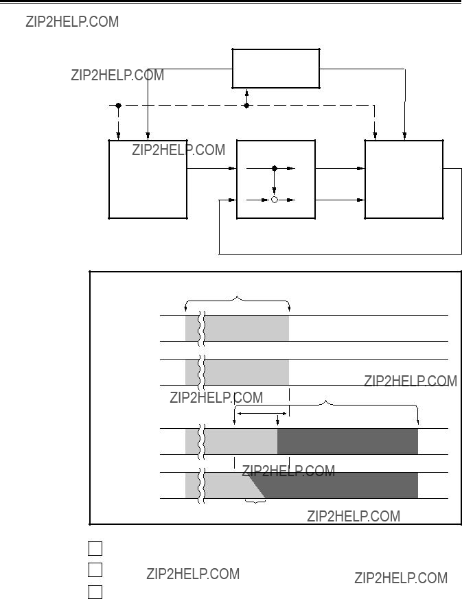
Servo reference
This unit automatically selects the input video signal selected by the INPUT switch, the reference video signal supplied from the REF VIDEO input connector or the internal sync signal as the servo reference signal.
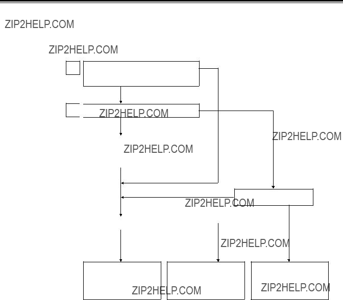
When the signal is selected, the unit???s mode and servo reference stand in the relationship shown in the flowchart presented below.
???
1 What is the SERVO REF on the setup menu No. 304 setting?
AUTO
2 
 Is the unit in the recording mode?
NO
EXT
YES
NO
NO
YES
Is the input video signal available?
YES
The REF VIDEO input signal serves as the reference signal.
The internal sync signal serves as the reference signal.
The input video signal serves as the reference signal.
??? 82 ???

Servo reference setting tables
The servo reference signal is switched as shown in the tables below depending on the servo reference setting, deck mode and what input signal is available. When the mode is transferred to editing or recording/playback, the image may be disturbed and the transfer may be delayed if the references during playback and recording do not match.
??? During playback or special playback
??? ??? denotes that the signal is supplied: ????????? denotes that the signal is not supplied.
??? 83 ???
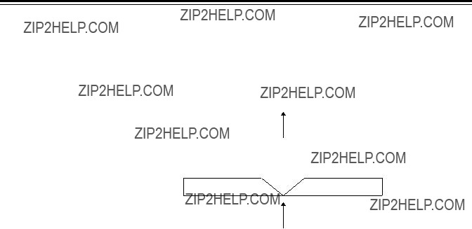
Audio V Fade Function
When editing tapes, the edit point splicing selection (setup menu No. 309 and 310) information is recorded on the tape. This information is then sensed during playback, and V fade or cut processing is automatically performed for these sections. [However, only when the playback fade selection (No. 719) is AUTO.]
When the edit point splicing selection (setup menu No. 309 and 310) is CUT
Noise appears at the edit splice.
When the edit point splicing selection (setup menu No. 309 and 310) is FADE
V fade is performed instantaneously to eliminate the noise.
<Notes>
???When the playback fade selection (No. 719) is CUT, cut processing is performed for all splices.
???When the playback fade selection (No. 719) is FADE, V fade processing is performed for all splices.
??? 84 ???
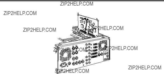
Printed circuit board
??? 85 ???
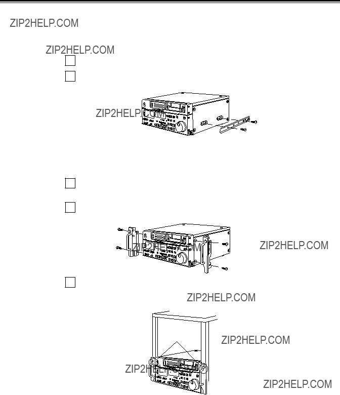
Rack mounting
The unit can be mounted into a
1
2
Remove the screws on the left and right sides of the unit.
Use the removed screw to attach the inner members of the slide rails.
3
4
5
Inner member
The length of the screws used is subject to restriction. If some of the mounting screws have been lost or misplaced, use screws which are less than 0.4" long in their place. Use four screws to secure each inner member.
Attach the outer member brackets to the rack.
Check that the height is the same for the left and right brackets.
Attach the
Remove the 4 rubber legs from the bottom of the unit, and install the unit in the rack. After the unit has been installed, check that it moves smoothly along the rails.
EIA Standard rack
Fasten it to the rack with set screws.
<Notes>
???Keep the temperature inside the rack to between +41??F (5??C) and +104??F (40??C).
???Bolt the rack securely to the floor so that it will not topple over when the VTR is drawn out.
???86 ???

Video head cleaning
This unit has an auto head cleaning function which automatically reduces the dirt on the heads. However, to further increase the unit???s reliability, it is recommended that its video heads be cleaned every day.
Use the cleaning fluid designated by Panasonic.
Condensation
Condensation occurs due to the same principle involved when droplets of water form on a window pane of a heated room. It occurs when the unit or tape is moved between places where the temperature or humidity varies greatly or when, for instance:
???It is moved to a very humid place full of steam or a room immediately after it has been heated up.
???It is suddenly moved from a cold location to a hot or humid location.
When moving the unit to locations such as these, leave it standing for about 10 minutes rather than switching on the power immediately.
If condensation has formed on or in the unit, the AUTO OFF lamp lights and the cassette tape is automatically ejected.
Keep the power supplied and simply wait until the AUTO OFF lamp goes off.
??? 87 ???
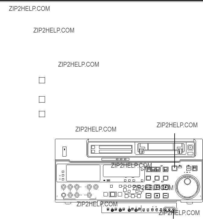
Error messages
When a warning occurs in this unit, the warning lamp lights up.
Opening the DIAG menu will display the warning description on the counter display and the monitor. Also, when an abnormal operation is detected in this unit, the AUTO OFF lamp lights up and a message appears on the counter display.
DIAG menu
This display the VCR information.
VCR information includes ???WARNING??? information and ???HOURS METER??? (usage time) information. A DIAG menu appears on the monitor when the monitor is connected to the VIDEO OUT 3 connector on the connector section.
Displaying the DIAG menu
1 Press the DIAG button.
The DIAG menu screen is displayed on the monitor, and the message is displayed on the counter display.
2 The ???WARNING??? information and ???HOURS METER??? information can be switched by pressing the search buttons.
3 Press the DIAG button again to return to the original display.
1, 3
???WARNING??? information display
???A warning message is displayed whenever a warning occurs (the warning lamp lights up). When warnings have not been detected, ???NO WARNING??? is displayed.
???When multiple warning occur, the descriptions for each warning can be checked by turning the search dial.
???88 ???

Displaying the ???HOURS METER??? information
Turn the search dial to move the cursor ( ???). The description for the item where the cursor is located is shown on the counter display.
<Notes>
???The resettable items in the ???HOURS METER??? information are reset by the shop when performing maintenance or other work.
???The search buttons and the search dial cannot be operated while the DIAG menu is displayed.
If ???T&S&M??? is selected in the setup menu No. 003 (DISPLAY SEL), a message appears in the mode display whenever a warning or error occurs. When multiple events occur, the event with the highest priority is displayed.
Warning messages
??? 89 ???

Table of AUTO OFF Error messages
??? 90 ???
??? 91 ???

1.Introduction
(1)The VTR can be operated by commands when the
(See command table on pages 95 ??? 97.)
(2)Conditions for acknowledging commands from
The front panel REMOTE/LOCAL switch must be at REMOTE. The setup menu item No. 204 ???RS232C SEL??? must be ON.
If the above conditions are not met, [ACK] + [STX]ER001[EXT] is returned to the external unit.
Whether the [ACK] code is returned depends on the setting which has been selected for setup menu item No. 209 ???RETURN ACK???.
2.Hardware specifications
External interface specifications
1)Connector specifications
Connector:
2)Example of connection with controller (PC)
???Using crossover cable with
???Using crossover cable with
??? 92 ???

3. Software specifications
Protocol
1) Communication parameters
The underlining indicates the factory settings.
Any changes to the settings can be made using the setup menu items listed below.
20h<XX<7Fh
??? [command]: Command identifier; a
???Outline of send procedure from controller
1.The send command starts with STX (start of text = 02h). The command is then identified by COMMAND which follows and the data is added as required.
The format ends with ETX (end of text = 03h).
2.When a different command is to be sent, a response is awaited from the VTR, and then the command is sent. (See page 94.)
3.If STX is sent again before ETX is sent, the receive data buffer inside the VTR is cleared. A command error is returned to the controller, and the data is newly processed with STX which was received again at the head.
??? 93 ???

3)Return format [VTR ??? controller (PC)]
The following responses are made to the command. If necessary, more than one response is made.
??? When the communication has terminated normally
1.The receive completion message is returned. [ACK]
06h
2.The execution completion message is returned.
[STX] [command] [data] [ETX] 02h XX XX XX
??? [command]: This is the message (data) which is returned or the execution completion message identifier.
???When the communication has terminated abnormally
[NACK]
15h
???When processing is not possible due to incorrect data or trouble in the VTR
1. The receive completion message is returned. [ACK]
06h
2.An error code is returned. [STX] E R N1 N2 N3 [ETX]
02h Error code 03h
4. Error code table
ER001: Invalid command
???Unsupported command received.
???Error in command execution ER002: Parameter error
ER102: VTR mode error (front loading motor)
ER103: VTR mode error (loading motor)
ER104: VTR mode error (drum, capstan system)
ER105: VTR mode error (reel system)
ER106: VTR mode error (tension system)
ER108: VTR dew error
ER1FF: VTR system error
??? 94 ???

5.Command table
(1)Commands relating to operation control <Notes>
???As for the return (completion) message, [ACK] is first returned when data is received, and the execution message is subsequently returned. It is only the execution message which is listed in this table.
???In the case of commands not listed in the table, ER001 (invalid command) is returned after [ACK] has been returned.
??? 95 ???

??? 96 ???

(2)Commands relating to inquiries <Notes>
???As for the return (completion) message, [ACK] is first returned when data is received, and the execution message is subsequently returned. It is only the execution message which is listed in this table.
???In the case of commands not listed in the table, ER001 (invalid command) is returned after [ACK] has been returned.
??? 97 ???

(3) Microsoft QuickBASIC sample program
CLS
STX$ = CHR$(&H2): ETX$ = CHR$ (&H3): NAK$ = CHR$(15): ACK$ = CHR$(&H6) PRINT "***
PRINT "Type Command 'QUIT' to quit."
REM *** Communication Port Initial & Open ***
REM Port 1,9600Bps,No parity,8 bit data,1 stop bit
OPEN "COM1:9600,N,8,1" FOR RANDOM AS #1 LEN = 256
REM *** Input Command & Send Command ***
SendCmd:
INPUT "Input Command ="; SEND$
IF SEND$ = "QUIT" THEN GOTO ProgEnd
PRINT #1, STX$ + SEND$ + ETX$
REM *** Wait for Receive Command ***
WHILE LOC(1) = 0 WAITKEY$ = INKEY$
IF WAITKEY$ = "Q" THEN PRINT "*** Quit ***": GOTO ProgEnd
WEND
REM *** Receive Command ***
RecvCmd:
RECV$ = INPUT$(1, #1)
IF RECV$ = STX$ THEN RECV$ = "[Stx]"
IF RECV$ = ACK$ THEN RECV$ = "[Ack]"
IF RECV$ = NAK$ THEN RECV$ = "[Nak]"
IF RECV$ = ETX$ THEN BUFFER$ = BUFFER$ + "[Etx]": GOTO DispOut BUFFER$ = BUFFER$ + RECV$
GOTO RecvCmd
REM *** Output Receive Command ***
DispOut:
PRINT "Receive Command ="; BUFFER$
BUFFER$ = ""
GOTO SendCmd
REM *** End Program ***
ProgEnd:
CLOSE
END
MICROSOFT QUICKBASIC is a registered trade mark of Microsoft Corporation.
??? 98 ???

Connector signals
VIDEO IN
VIDEO OUT
AUDIO IN
AUDIO OUT
Pin No. Signal
1GND
2HOT
3COLD
REMOTE IN/OUT
??? 99 ???

Connector signals
PARALLEL REMOTE (25P)
<Notes>
???COMMAND pins: TTL level, active low, ???100ms edge electrical signal.
???STATUS pins: open collector, sink current 6 mA
ENCODER REMOTE (15P)
??? 100 ???
Specifications
GENERAL
(Video signals adjustment)
AUDIO
(Digital audio)
(Cue track)
Frequency response:300 Hz to 6 kHz ??3 dB
(Audio input connector)
(Audio output connector)
Other input/output connector
Weight and dimensions shown are approximately.
Specifications are subject to change without notice.
??? 101 ???

PANASONIC BROADCAST & DIGITAL SYSTEMS COMPANY
DIVISION OF MATSUSHITA ELECTRIC CORPORATION OF AMERICA
PARTS INFORMATION & ORDERING:
9:00 a.m. ??? 5:00 p.m. (EST) (800)
TECHNICAL SUPPORT:
Emergency 24 Hour Parts & Service (800)
TRAINING INFORMATION:
Digital System Products - (201)
Panasonic Canada Inc.
5770 Ambler Drive, Mississauga, Ontario L4W 2T3 (905)
Panasonic de Mexico S.A. de C.V.
Av angel Urraza Num. 1209 Col. de Valle 03100 Mexico, D.F. (52) 1 951 2127