ORDER No, MTNC021139C1
B14
Assembly Guide
HDTV DIGITAL RECEIVER
This Assembly Guide is issued as a service
for reburbishing purposes.
ORDER No, MTNC021139C1
B14
Assembly Guide
HDTV DIGITAL RECEIVER
This Assembly Guide is issued as a service
for reburbishing purposes.


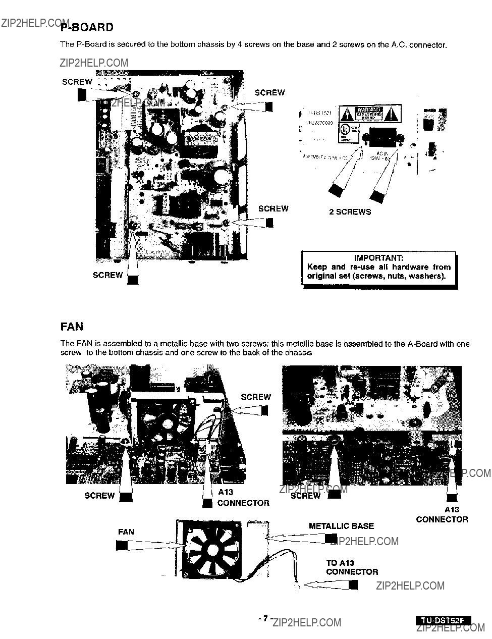
TOP COVER
The top cover is secured to the bottom chassis by 3 screws
REMOVAL:
Remove the 3 screws from the back that secure the cover.
Slide the cover completely to the back of the set.
ASSEMBLY:
Slide the top cover all the way to the front of the set.
Confirm that the top cover tabs are correctly assembled into the bottom chassis as shown.

FRONT PANEL
The front panel is secured to the bottom chassis by the side tabs.
TAB
PULL FLAT CABLE UPWARDS
FLAT CABLE
TAB
REMOVAL
Unplug the flat cable from the
Push the left and right sides of the bottom chassis near the tabs, to release the front panel.
ASSEMBLY
Confirm that all the marks from the front panel match with the spaces in the bottom of the chassis and insert firmly until the panel is secured to the bottom chassis by the side tabs.

FRONT PANEL ASSEMBLY
SIGNAL LED KEY BUTTONS
[]
/
POWER BUTTON
DISASSEMBLY
Remove the screw and the GND metal. Open the locking tabs to release the
VIDEO OUT LEDS
/
/
Panas_c
FLAT CABLE
from the panel.
The IR guide and the SIGNAL LED panel are mounted into a plastic guide on the panel.
SIGNAL LED
IR GUIDE

SCREW
SCREW
The connector has
to bottom chassis by 4 screws, 5 screws on the back, washer and
SCREWSCREW,
a tab, try to pull the connector from this tab with a flat screw.
TAB
Keep and
original set. (Screws, nuts, washer).
IIMPORTANT:
the Hex nut on the tuner
I
The
IllSCREW
FAN
The FAN is assembled to a metallic base with two screws; this metallic base is assembled to the
SCREW

BOTTOM VIEW
The bottom chassis include 4
::::

PACKING BOX
Assembly the box as shown:
BACK
BACK
FRONT
FRONT
BACK
FRONT
FRONT

CUSHION BOX
Assembly the cushion box as shown.
TOP VIEW
n
SIDE VIEW
FRONT
PACKING
Insert the cushion box into the packing box as shown.
Place the reinforcement carton on the rear side of the assembly.
Keep the notch of the cushion box to the front.
Place the remote control on the left side and the AC cord on the right side.
REINFORCEMENT CARTON
PACKING THE SET
Place the set inside the plastic bag (450x400mm) and fold the remaining bag on top of the set and fix it with tape as shown.
The fanbag (manuals, warranty, service center sheet, etc.) should be placed on top of the set.

REPLACEMENT PARTS LIST FOR REBURBISHED
ReF,No.
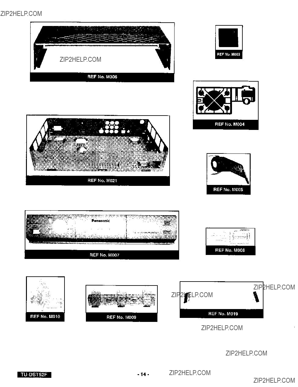
M001 EUR7613Z50
M002 UR76EC0303A
M003 TBLG3017
M004 TBXA19603A
M005
M006 TKF2AA00103
M007 TKP2AA0494S
M008 TKP2AA0501
M009 TKP2AA0771
M010 TKX2AA0111
M011 TPC2AA1024
M012 TPD2AA00721
M013 TPD2AG0181
M014 TPE2AH0031
M015 TPE2A40055
M016
M017
M018 TSXF094
M019 TSXL092
M020 TSX2AA0261
M021 TUA2AA0034
M022 TUX2AXO111
M023
M024 UDQFSEH57
M025 OWG95FN
M026 0NG38AFN
M027 04F32219
M029 XTV2.6+6JFX
MO31 TNP2AA115S
M033 TNP2AH044S
DESCRIPTION
REMOTE CONTROL
BATTERY COVER, REMOTE CONTROL
FOOT, RUBBER
BUTFON
GND SPRING
TOP COVER
FRONT PANEL
LED PANEL
MODE LED PANEL
IR GUIDE
PKG, CARTON
PKG, CUSHION
PKG, REINFORCEMENT
BAG PLASTIC 450X400
PKG., BAG 9.5 X 14
MANUAL, OWNERS
CARD, REGISTRATION
ASSY, NM CABLE
CABLE ASSY.
LINE CORD, AC
BOTTOM CHASSIS
BRKT, FAN
BATTERY (AA)
FAN
WSHR, RND (9.5X 12.7)
NUT,
TAPE, ADHES. POLYESTER
SCREWS (FOR FAN)
K;BOARD:

I
\

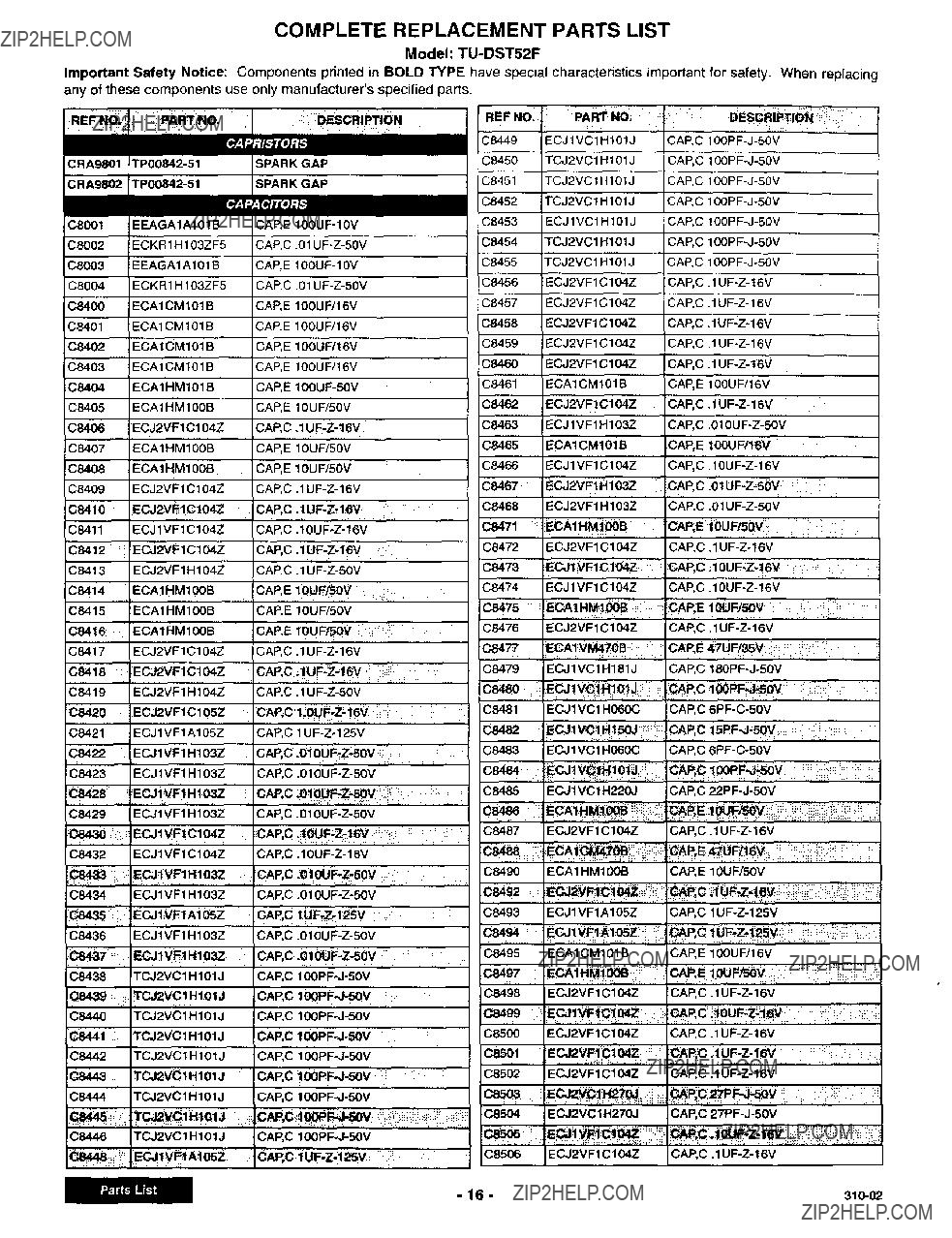
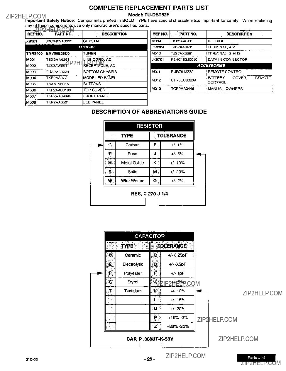
COMPLETE REPLACEMENT PARTS LIST
Model:
Important Safety Notice: Components printed in BOLD TYPE have special characteristics
any of these components use only manufacturer'sspecified parts.
important for safety. When replacing
CAP,C
CAP,C
CAP,C
CAP,C .01
P,E1ouF,5ov,,
CAP,
CAP, C
CAP, C i_PF_,_50V
CAP, C
CAP, C
CAP, C
CAP, C
CAP.E 10UF/50V
CAP, C
CAP, E 100UF/16V
CAP,
_P.C t UF;Z, lSV
CAP, C
CAP,

COMPLETE REPLACEMENT PARTS LIST
Model:
Important Safety Notice: Components printed in BOLD TYPE have special characteristics important for safety. When replacing any of these components use only manufacturer'sspecified parts.

COMPLETE REPLACEMENT PARTS LIST
Model:
Important Safety Notice: Components printed in BOLD TYPE have special characteristics important for safety. When replacing any of these components use only manufacturer'sspecified parts.

COMPLETE REPLACEMENT PARTS LIST
Model:
Important Safety Notice: Components printed in BOLD TYPE have special characteristics important for safety. When replacing
any of these components use only manufacturer'sspecified parts.
C8775 ECJ2VF1C104Z
C8776 ECJ2VFIC104Z
C8777 ECJ1VF1C104Z
C8778 ECJIVFlCl04Z
C8779 ECJ2VF1C104Z
C8781 ECJIVFlCl04Z
C8782 ECJ2VF1C104Z
C8783 ECJ2VFIC104Z
C8784 ECJ1VFIC104Z
C8785 ECJ2VF1C104Z
C8786 ECJ2VF1C104Z
C8787 ECJ2VFIC104Z
C8788 ECJ2VFlCl04Z
C8789 ECJ2VFIC104Z
C8790 ECJ1VE1 Cl 04Z
C8791 ECJ1VFICIO4Z
C8792 ECJ2VF1C 104Z
C8793 ECJ2VF1C 104Z
C8794 ECAlCM101B
C8795 ECA1CM10tB
C87_ ECJ2VC1H151J
C8797 ECJ2VC1H151J
C8798 ECJ2VC1 H151J
C8799 ECJ2VC1H080D
C8800 ECJ2VC1 H080D
C8801 ECJ2VC'IHO80D
C8802 ECJ1VC1H151J
C8803 ECJ2VCtH151J
C8804 ECJ2VC1Hi51J
else05
C8806 ECJIVFIC104Z
EC,JIVFlC104Z
C8808 ECAICM221B
08810 Ec.J2vclHto
C8811 ECJ2VCIH102J
Ce_12
C8813 ECJ1VCIH220J
C8822 ECJ1VB1CIO4K
C8823 ECAIHM101B
ECA1HM100B
C8969 ECJ2VB1 C104K
C8970 ECJ2VB1 Cl 04K
C8971 ECAIHM100B
C8972 ECAIHM100B
C8973 ECA1HM100B
C8974
C8975 ECA1HM100B
_76
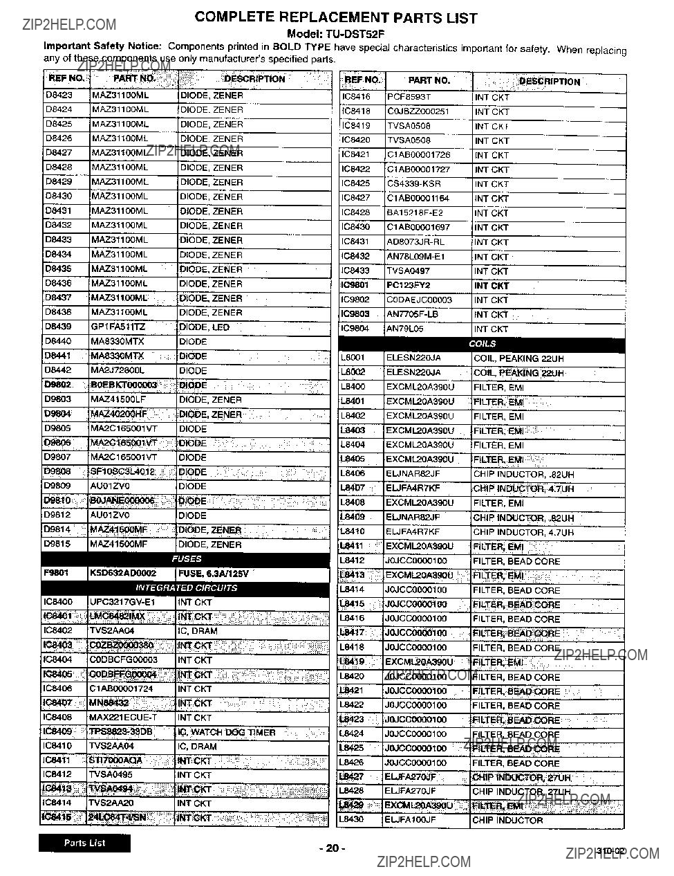
COMPLETE REPLACEMENT PARTS LIST
Model:
Important Safety Notice: Components printed in BOLD TYPE have special characteristics important for safety. When replacing any of these components use only manufacturer's specified parts.
D8423 MAZ3110OML
D8424 MAZ31100ML
D8425 MAZ31100ML
D8426 MAZ31100ML
D8427 MAZ3tl00ML
D8428 MAZ31100ML
D8429 MAZ31100ML
D8430 MAZ31100ML
D8431 MAZ31100ML
D8432 MAZ31100ML
D8433 MAZ31100ML
D8434 MAZ31100ML
D8435 MAZ31100ML
D8436 MAZ31100ML
D8437 MAZ31100ML
D8438 MAZ31100ML
D8439 GPt FA511TZ
D8440 MA8330MTX
D8441 MA8330MTX
D8442 MA2J72800L
D9802 BOEBKT000003
D9803 MAZ41500LF
D9804 AZ402OOHF
D9805 MA2C165001VT
D9806 ! MA2Gl_50_i _
D9807 MA2C165001VT
D9808
D9809 AU01ZV0
D9810
D9812 AU01ZV0
iD9814 ; M_tSOOMF
D9815 M,1_.4151X)MF
F9801 K5_32AI_[)002
IC8400
IC8402 TVS2AA04
IC8404 CODBCFG00003
IC8406 C1A_1724
_C84071!;iiii_i
IC8408
IC8410 TVS2._04
IC84il _tI_AQA,
IC8412 TVSA0495
108414 TVS2AA20
E.C.P,,O"
FUSE, 6.3A/125V
INT CKT
IC, DRAM
INT CKT
INT CKT
i_CKT
COMPLETE REPLACEMENT PARTS LIST
Model:
Important Safety Notice: Components printed in BOLD TYPE have special characteristics important for safety. When replacing any of these components use only manufacturer's specified pads.

COMPLETE REPLACEMENT PARTS LIST
Model:
Important Safety Notice: Components printed in BOLD TYPE have special characteristics important for safety. When replacing any of these components use only manufacturer's specified parts,
R8529 ERJ6GEYJ105V RES,M

COMPLETE REPLACEMENT PARTS LIST
Model:
Important Safety Notice: Components printed in BOLD TYPE have special characteristics important for safety. When replacing any of these components use only manufacturer'sspecified parts.

COMPLETE REPLACEMENT PARTS LIST
Model:
Important Safety Notice: Components printed in BOLD TYPE have special characteristics important for safety. When replacing any of these components use only manufacturer's specified parts.
COMPLETE REPLACEMENT PARTS LIST
Model:
Important Safety Notice: Components printed in BOLD TYPE have special characteristics important for safety. When replacing any of these components use only manufacturer's specified parts.
REF NO. PART NO,DESCRIPTIONREF NO, PART NO.DESCRip_ON
DESCRIPTION OF ABBREVIATIONS GUIDE
RES, C
1 I
CAP,
J

Panasonic
PRINTED IN USA
K02110050PL1128