Caution
Observe the following cautions when using this unit.
???This unit is designed for use exclusively in automobiles.
???Do not operate the unit for a prolonged period with the engine turned off.
Operating the audio system for a long period of time with the engine turned off will drain the battery.
???Do not expose the unit to direct sunlight or excessive heat.
Otherwise these will raise the interior temperature of the unit, and it may lead to smoke, ???re, or other damage to the unit.
???Do not use the product where it will be exposed to water, moisture, or dust.
Exposure of the unit to water, moisture, or dust may lead to smoke, ???re, or other damage to the unit. Make especially sure that the unit does not get wet in car washes or on rainy days.
Caution
Observe the following cautions when installing.
???If your car is equipped with air bag and/or anti-theft systems speci???c procedures may be required for connection and disconnection of the battery to install this product.
???FAILURE TO FOLLOW THE PROCEDURE MAY RESULT
IN THE UNINTENDED DEPLOYMENT OF AIR BAGS
OR ACTIVATION OF THE ANTI-THEFT SYSTEM
RESULTING IN DAMAGE TO THE VEHICLE AND
PERSONAL INJURY.
???Refer wiring and installation to quali???ed service personnel.
Installation of this unit requires special skills and experience. For maximum safety, have it installed by your dealer. Panasonic is not liable for any problems resulting from your own installation of the unit.
???Follow the instructions to install and wire the product.
Not following the instructions to properly install and wire the product could cause an accident or ???re.
???Take care not to damage the leads.
When wiring, take care not to damage the leads. Prevent them from getting caught in the vehicle chassis, screws, and moving parts such as seat rails. Do not scratch, pull, bend or twist the leads. Do not run them near heat sources or place heavy objects on them. If leads must be run over sharp metal edges, protect the leads by winding them with vinyl tape or similar protection.
???Use the designated parts and tools for installation.
Use the supplied or designated parts and appropriate tools to install the product. The use of parts other than those supplied or designated may result in internal damage to the unit. Faulty installation may lead to an accident, a malfunction or ???re.
???Do not install the product where it is exposed to strong vibrations or is unstable.
Avoid slanted or strongly curved surfaces for installation. If the installation is not stable, the unit may fall down while driving and this can lead to an accident or injury.
???Ware gloves for safety. Make sure that wiring is completed before installation.
???To prevent damage to the unit, do not connect the power connector until the whole wiring is completed.
???Never mount the unit in any of the following locations to avoid damage due to overheating;
???Near the heater port.
???Places like the dashboard or rear deck, where it may be exposed to direct sunlight.
???Do not mount the unit near the door, where it could be exposed to rain.
???You run the risk of interfering with the mounting or causing damage by drilling into the gas tank, a wiring harness, or other component.
???Note that if your car has a driving computer or a navigation computer, disconnecting the cable from the battery may clear the memory.
???Fit a vinyl cap over unused connection terminals, to prevent contact with metal parts etc.
Observe the following cautions when handling the batteries for the remote control unit.
Proper Use of the Batteries
???Use only speci???ed battery (CR2025).
???Match the polarity of the battery with the (???) and (???) marks in the battery case.
???Replace a dead battery as soon as possible.
???Remove the battery from the remote control unit when not using it for an extended period of time.
???Insulate the battery (by placing them in a plastic bag or covering them with vinyl tape) before disposal or storage.
???Do not disassemble, recharge, heat or short the battery. Do not throw a battery into a ???re or water.
???Follow local regulations when disposing of a battery.
???Improper use of a battery may cause overheating, an explosion or ignition, resulting in injury or a ???re.
In case of battery leakage
???Thoroughly wipe the battery liquid off the battery case and insert new battery.
???If any part of your body or clothing comes into contact with battery liquid, wash it with plenty of water.
???If battery liquid comes into contact with your eyes, wash them with plenty of water and get immediate medical attention.
Please follow the laws and regulations of your province or country for installation of the unit.
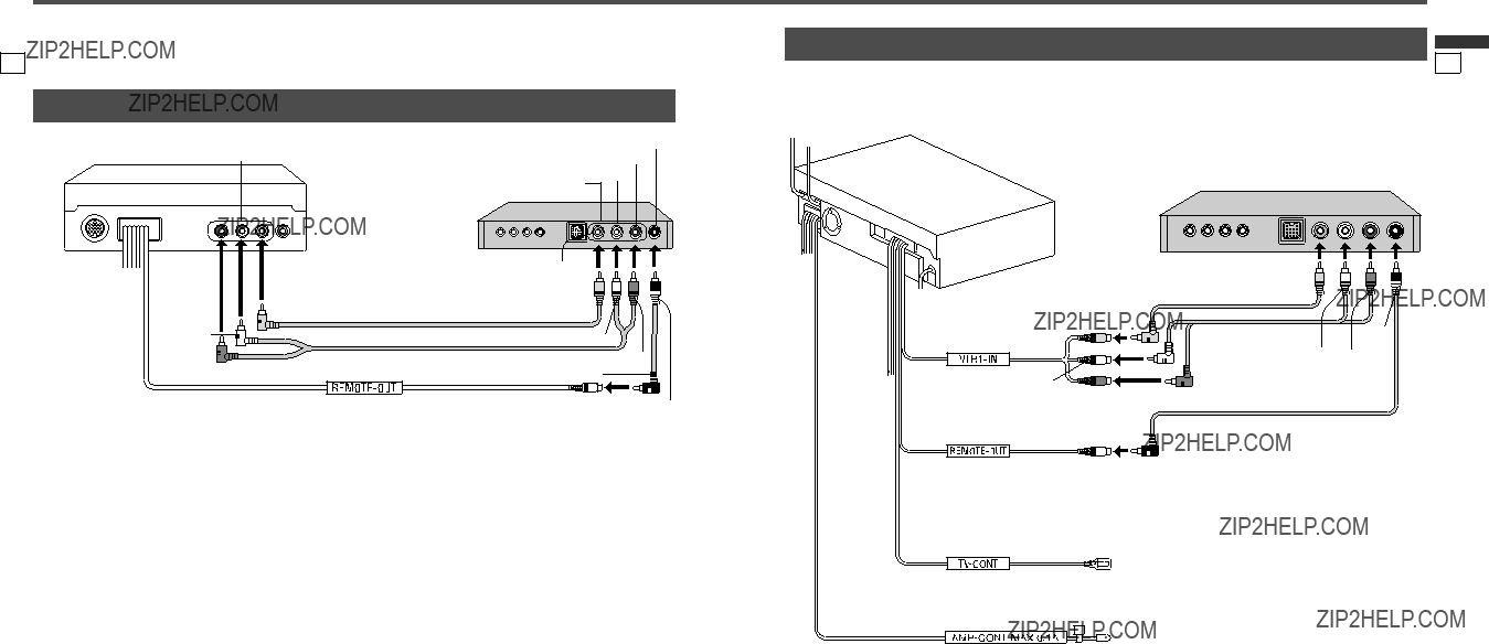
Connection of Parking (Side)
Brake Connecting Lead
This system is designated so that you cannot see TV or motion pictures while you are driving.
???Park your car in a safe and pull the parking brake (side brake) lever before watching the monitor.
???If a rear monitor (option) is connected to this unit, you can continually see the rear monitor image even if the parking brake (side brake) has not been pulled on.
 Warning
When you connect external devices (option), be sure to connect the parking brake (side brake) connection lead. (page 21)
Note:
??? Only English is displayed on the OSD screen.


 Warning
 Caution
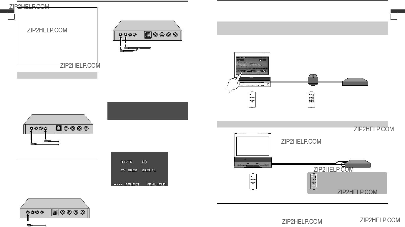


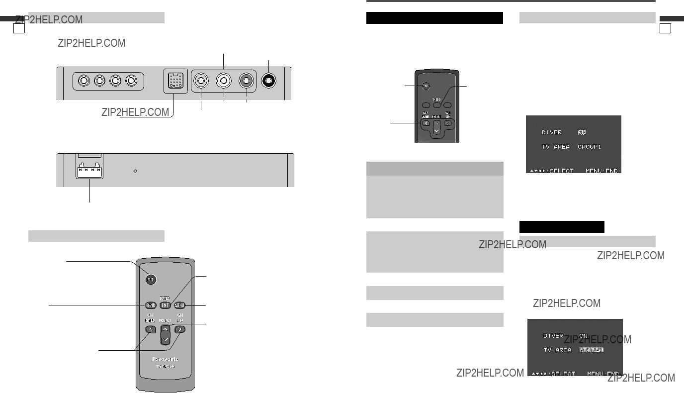


 [MENU]
 Warning
 Caution
 Caution
 Caution
 Caution
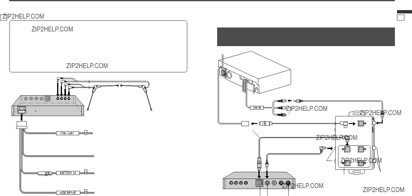
 Caution

 Warning