ELECTRONIC MOhJLAR SWITCHING SYS,TEM
Panasonic
Please read this manual before connecting the
Quick Reference Card for Standard Telephone can be found on pages.+22 through
ELECTRONIC MOhJLAR SWITCHING SYS,TEM
Panasonic
Please read this manual before connecting the
Quick Reference Card for Standard Telephone can be found on pages.+22 through

Thank you for purchasing the Panasonic Model
System Component
Description
Electronic Modular Switching System
EMSS Proprietary Telephotle-
EMSS Proprietary Telephorze with LCD EMSS Proprietary Telephone
DSS Console
Doorphone Adaptor
Doorphotze..___
Headset
System
NOTIFY THE TELEPHONE COMPANY
Installation must be performed by the telephone company or a qualified professional installer.
Notify the Telephone Company
Before connecting this equipment to any telephone, call the telephone company and inform them of the following:
:.???..???
aPresent FCC Regulations prohibit connecting this unit to a party line, or to a coin operated telephone.
Please read the section on ???Telephone Company and FCC Requirements and
Responsibilities??? on page
.n
The serial number of this product may be found on the label affixed to the bottom qf the unit. You should note the serial number of this unit in the space provided and retain this book as a permanent record of your purchase to aid in identification in the event of theft.
MODEL NO.:
I SERIAL NO.:
For your future reference
DATE OF PURCHASE
NAME OF DEALER
DEALER???S ADDRESS
TABLE CiF CONTENTS ???
Name and Location ...........................................
Installation ......................................................
Connection .....................................................
Cotltlecriotl of a Sratldard Telephone to Extensions. ..................
Comreclion of the DSS Console
to an Extension. ...............................................
External Music Source ..........................................
Pagitlg Equiptnetlt ...............................................
Cotltlecrion of The Opriotlal Doorphotle
To Cotltlecr a Polarity Sensitive Telephone ..........................
To Cotmecr Opriotlal System
To Connect Pritlter .............................................
7
Programming

Delayed Ringing Count Selection ..........
Intercom Alerting Mode .................
Programmable Doorphone .............
Dial Call Pickup Group Assignment. ......
Account Code Input Mode ..............
Duration Time Count Start Mode .........
SMDR Communication Parameters ......
System Data Dump .....................
SMDR IncominglOutgoing Selection . . . . .
Hold Time Reminder ...................
Hold Recall Time Set ...................
Programmable External Paging Access Tone
Programmable Secret Speed Dial .........
Hookswitch Flash Timing ...............
Disconnect Time .......................
Calling Party Control (CPC) Signal .......
DSS Button Mode ....................
Transfer Recall Time ..................
M3IFWD Selection (for KX- T308.50,
.......
.......
.......
.......
.......
DetQiled Feature Description and Operation for EMSS Proprietary Telephone
To Make Calls
Inter Ofice Calling (Intercom) . . . . . . . . . . . . . . . . . . . . . . . . . . . . . . .
Calling Doorphone. . . . . . . . . . . . . . . . . . . . . . . . . . . . . . . . . . . . . . . .
Distinctive Dial Tone . . . . . .

When a Line is Busy
. . . . . .
. . . . . .
. . . .
. . . . . .
.
. . . . . .
. . . . . .
.
.
.
.
.
.
While Having a Conversation
Call ot1 Hold ........................
Call otl Exciusive Hold ...............
Cottference .........................
Call Waiting. ........................
Call Transfer .......................
CalI
Call
Paging
Station Programming
. . . . . .
......
......
......
......
......
......
Operation for a Standard Telephone
To Make Calls ........................
When a Litle is Busy ..................
To Receive Calls ......................
While Havitlg a CotlversaGotl ............
Pagitig ...............................
Use of Other Feamres ..................
Statioti Progratnttiitig ..................
Troubleshooting
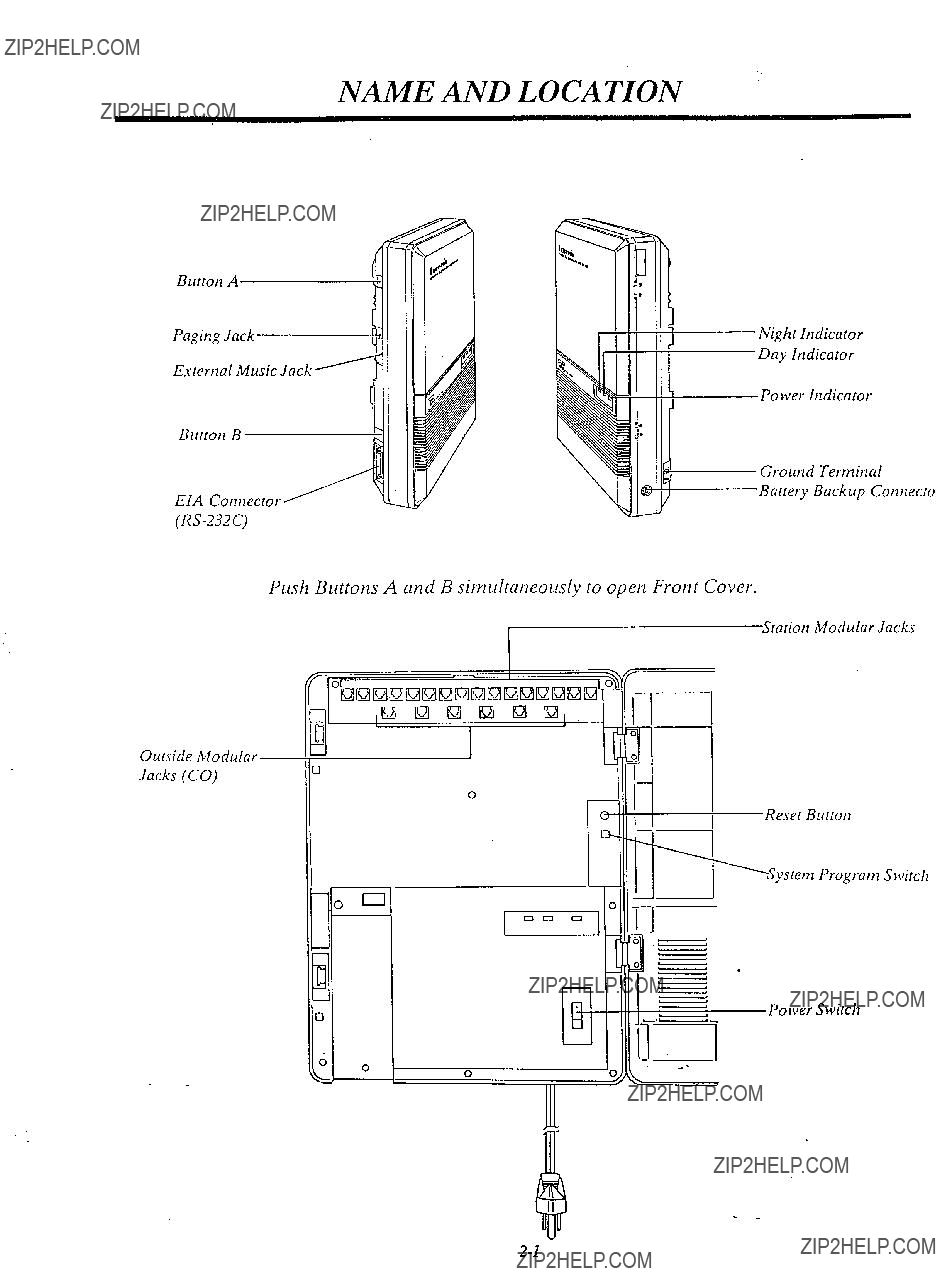
NAME AND LOCATION :
Night ltldicator Day Indicator
External Music Jack
Burtotl B
EIA Cotmector
Power Indicator
Ground Terminal
Buttery Backup Cotztlecio
Push Buttons A and B simultaneously to open Front Cover.
Outside Modular-
Jacks (CO)
0
I 0
3
1
7
???I
Reset Button
System Program Switch
*PowerSwiWh

INSTALLATION
Installation
Cautions
*Avoid insralling in the following places. (Doing so may resulr in malfunction, noise, or discoloration.)
1.In direct sunlighr and her, cold, or humid places. (Temperarure range:
2.Sulfuric gases produced .in areas where there are thermal springs, etc. may damage the equipment or contacls.
3.Places in which shocks or vibrations are frequent or strong.
4.Dusty places, or places where water or oil may come into contact with the unit.
5.Near
6.On or near computers, relexes, or other office equipmenr, as well as microwave ovens or air condirioners. (Ir is preferable not lo install in the same room with the above equipment.)
7.Near radio broadcast anlennas (including short wave).
8.Insrall at least 6 feet from radios and relevisiotls. (both rhe electronic modular switching system and EMSS proprierary telephones)
9.Do not obslrucr area around (he electronic modular swirching system. (for reasons of nlaitlfetlatlce atId
Cautions
1.Do not wire the telephone cable in parallel with the AC power source, computer, telex efc. If the cables run near rhose wires, shield the cables with metal tube ???or use shield cables and ground the shields.
2.When cables run on the floor, use protectors or the like lo protect the wires where they may be stepped on. Avoid wiring under carpets.
3.Avoid using the same AC 120 V power supply outlet for computers, telexes, and other office equipment. Otherwise, the
4.Please use one pair telephone wire telephone, data terminal, answering KX- T61620, KX- T61650, etc.).
for extension conneclion of (telephone) equiptnents such as standard machine, computer, etc., except proprietary telephone
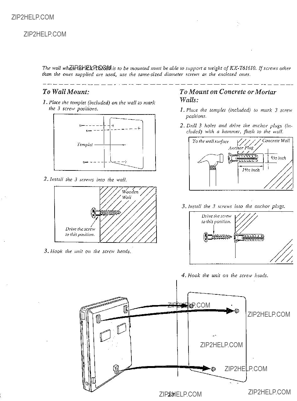
The wall where the
To Wall Mount:
1.Place the templet (included) on the wall to mark the 3 screw positions.
To Mount on Concrete or Mortar Walls:
1.Place the templet (included) to mark 3 screw positions.
2.Drill 3 holes and drive the anchor plugs (in- cluded) with a hammer, flush to the wall.
2. Install the 3 screws into the wall.
3. Install the 3 screws into the anchor plugs.
Drive the screw to this position.
3. Hook the unit on the screw heads.
4. Hook the unit on the screw heads.
CONNECTION
After all the connections are completed, turn the Power Switch ON.
If an extension does not operate properly (for example: The LCD of the
disconnect the telephone from the ejctension line and then connect again, or turn OFF SpeflkerAmplifierthe power switch of the
then ON again.
Opriotlai Sysrem
Unit
Doorphotw I
of tile
16 Esretlsiotz LitlesKX- T6162Of KX- T6165Ol KX- T3083O/KX- T3082Ol
(One pair)
Standard Telephone

IMPORTANT!!!
Surely connect the frame of the
1.Remove the battery cover from the compartment. (Fig. 1)
2.Connect the battery (included). (Fig. 2)
3.I~tstall the battery i,lto the battery compartment. (Fig. 3)
*Replace the battery every 5 years with

Caution
See ???During Installation??? page
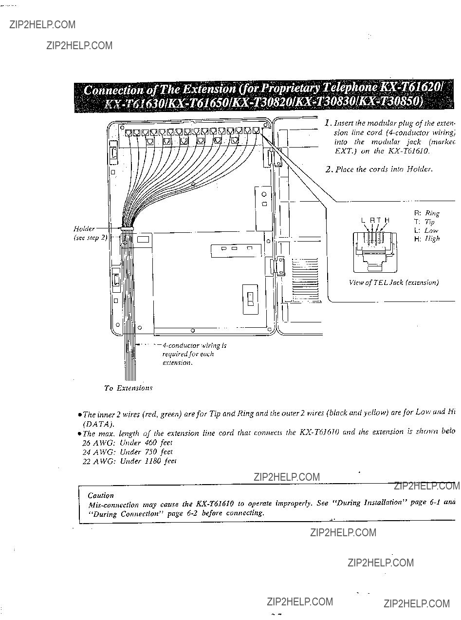
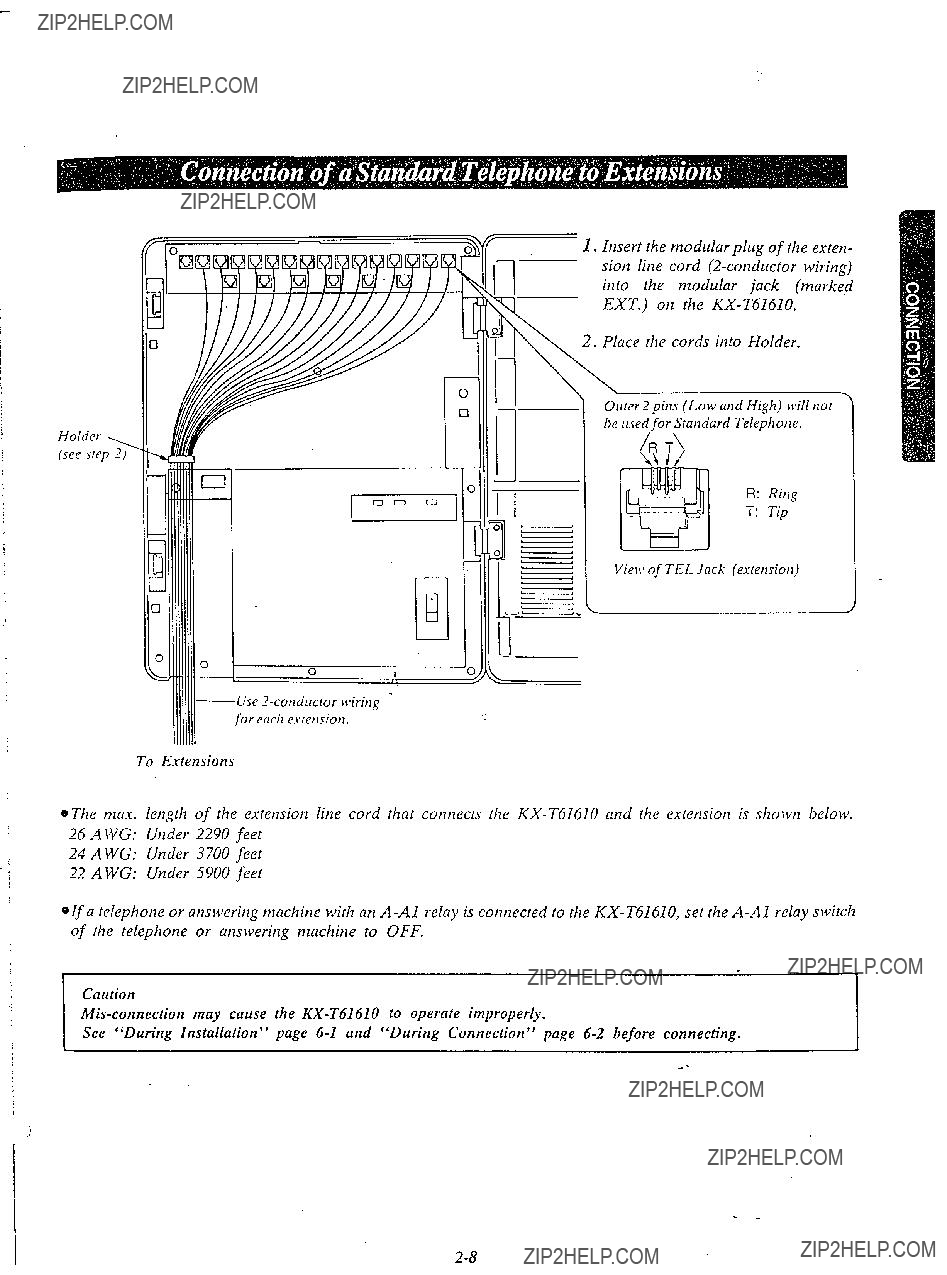
I. Insert the modular plug of the exten- sion line cord (6conductor wiring) into the modular jack (markeci EXT.) on the
2. Place the cords into Holder.
To Extensions
l The inner 2 wires (red, green) are for Tip and Ring and the outer 2 wires (black and yellow) are for LOW and Hi (DA TA).
l The max. length of the extension line cord that connects the
24 A WG: Under 750 feet
22 A WG: Under 1180 feet
Caution
???During Connection??? page
b k
Holder , (see srep 2)
1.Insert the modular plug of the exten- sion line cord
2.Place the cords into Holder.
\
Outer Zpins (Low and High) will not be Itsedfor Standard Telephone.
R: Ring
T: Tip
Vie)%???of TEL Jack (extension)
Use
To Extensions
"If a telephone or answering machine with an
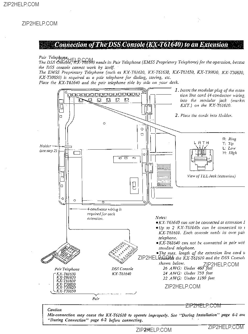
Pair Telephone
The DSS Console,
The EMSS Proprietary Telephone (such as
Place the
1. Insert the modular plug of the esten, sion line cord
2. Place the cords into Holder.
Holder \ -
(see step 2)
i
1
0
Pair Telephone
0 !
DSS Console
R: Ring
L RTH T: Tip
L: Low
H: High
View of TEL Jack (exremion)
l
telephone.
0 The max. length of the extension lille cord ti connects the
26 AWG: Under 460 feet
24 AWG: Under 750 feet
22 AWG: Under 1180 feet
Pair
Caution

Example:
If
(Paired extension is ext. 12).
1.Connect the
2.Connect the
eFor use the
Extetlsion 12
KX- T61630
To Use Full Extensions When the DSS .{1
Console is Connected
H
H The standard telephone connecred in parallel with
KX- T61640.
The operation has no concern between
Pair Telephone
KX- T61640
Standard This is not 1 Telephone ca pair telephone.
- -
resistance
Speaker
,\

. , For instaiiitlg the door
phone. lose the Optio/lal Doorphotle
Adaptor
(use tihe
1.
@ posh the adnpror
Doorp/~orte Adaptor to the
t .^,t~.nt ;t lnckq itlto the ribs of the flown 3??? ???,???L???L
1
mit.

2.Wiring conneCtion of the Doorphone
(A)Connect the doorphone adaptor to the terminal box using a
(B)Connect the wires of doorphone 1 to the red and green screws of the terminal box.
(C)Conrlect the tvires of doorphone 2 to the yellow and black screws of the terminal box.
Doorphone Adaptor
BLACK-
@The max. length of the telephone line cord that connects the
26 AWG: Under 230 feet
24 AWG: Under 370 feet
22 AWG: Under 590 feet
If the telephone you are using with the
1.Cotmeci all extension wiritlg lo the
2.Cotlfirtn that dialitlg can be done from all the estetlsiotls using a tone relephotle.
3.If a dialing cat1 tlof be dotle, rhe polarify berlcseen the exretlsiotl atld rhe
E.uerlsion
Cenirul Office Line
4.Ser rhe Power Switch ot1 the
5.Connect all Central O.ffice (CO) Lines.
6.Confirm that dialing can be done on following exrensiotis iisirig a rotze telephone.
Exlension Il.. .CO I
Extetisioti 12...CO 2
Extension 13... CO 3
Extension 14...CO 4
Esterisioti 15...CO 5
Extensiotz 16.. . CO 6
7. If dialing cat1 not be done, the polarity between rhe
Extension
Re\.ersehere
8. If any extetlsiort is changed or replaced, repeal these procedures (from step 1 through step 7).

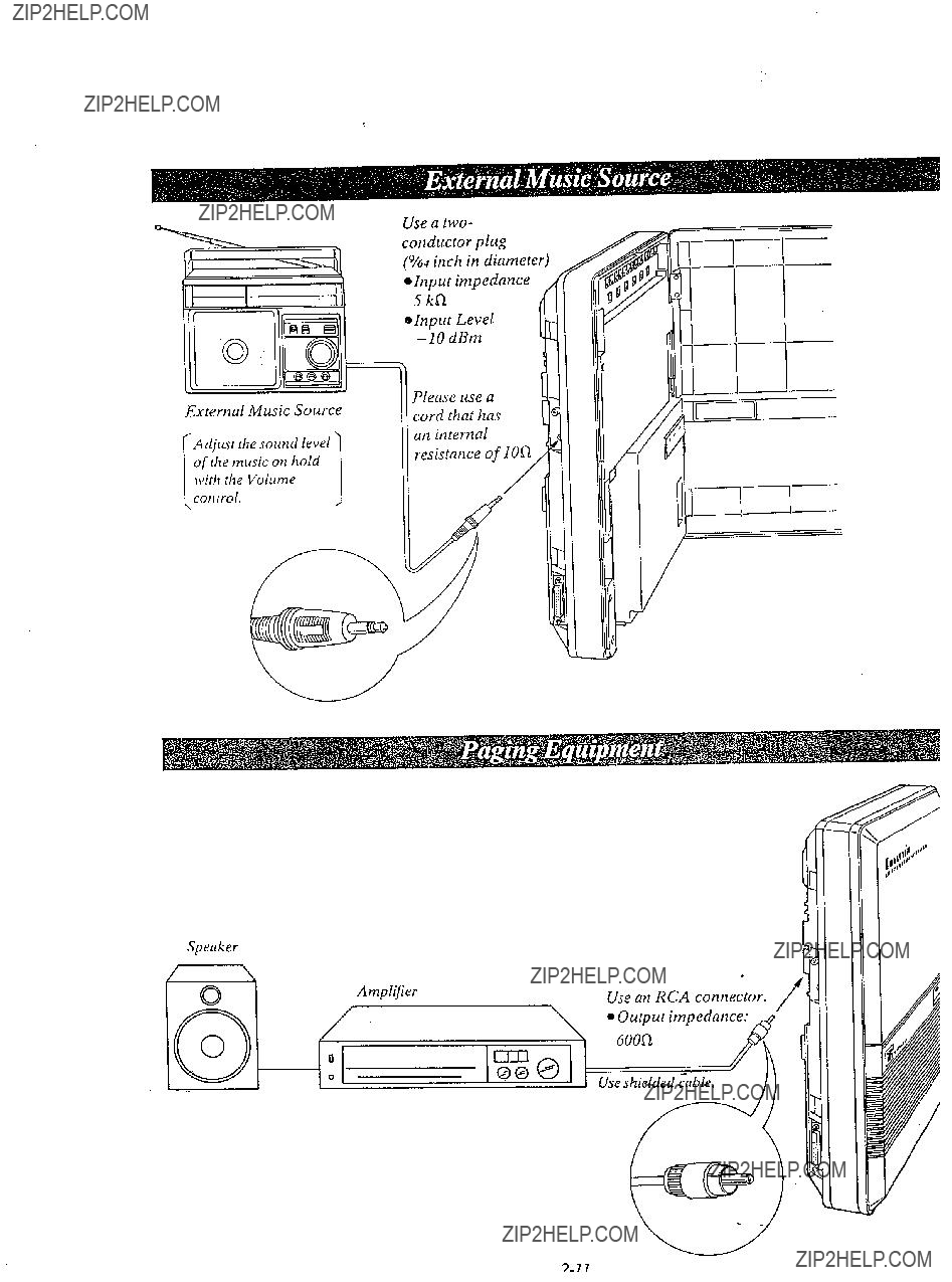
1.Connect the cord from the optional
2.Plug in the AC power cord from the
3.Turn on the Power Switch located on the
OApproximately 24 hours are required to recharge the
@The
l The Battery life is 3 years.
l A simple way to check the
elf the
eAC Primary Fuse, (250 V, 1.25 A)xl: Replace the fuse which is in the fuse hold located on the rear, if the CHARGE Indicate is off
(Keep the unit CMWJfrom heat.)
BATTERY LOW Indicator:
will be lit \vhile recharging is insfifj5cient.
CHARGE Indicator:
will be lit while the adaptor is being recharged.
-L

Serial Printe;
/*
Make cables so that the printer will be connected to the
Cables tnust be shielded and the maximum length is
6.5 feet.
Connection Chart:
???Panasonic data terminal;
If you connect this unit to a Panasonic Data Terminal, the Communication Parameter Transmit XONIXOFF on the Data Terminal must be set to the ???YES??? position.
For further details, see rhe Operating Instruc- tions of the Data Terminal.
When using special acieisories such as cable, the user should use those specified in this installation manual to comply with the limits for a Class A compuring device pursuarit co Subpart J of Part 15 of FCC Rules.

PROGRAMMING
To activate this system, the requirements from telephone company and the customer must be programmed once the Power Switch has beet1 turned on.
1.At extettsiotl 11:
All system programtnittg changes (example: sy???s- rem clear. station progratn clear, toll restrictiotl, hookswitch Posh timing.. .) are dotie throrigh estetfsioti Il.
OExtensiort II must always be a Panasonic model,
2. System Program Sw,itch setting:
The System Progratn Switch located ott the
3.Overlay:
This overlay is used for progratmnit~g the system and the program function names are inscribed on this card. Refer to page
4.Before systetn programming, operate the system clear and station program clear to set to the default data of the progratntnittg.
A. Systetn Clear: 1 Dial (99).
o???SYSTEtVI CLEAR??? lr???ill be displayed. 2 Press the NEXT button.
o???A LL CL E.4 R???? \c*ill be displayed.
3 Press the MEI\IORY button to clear system.
4 To exit from system clear. press the END brittott.
The followitlg feutures ure preset as the defatrlt
Preferred CO Litze Assignment Programmable Cull Waiting Dltratiotl Time Count Start Mode SMDR Cotntnunicutiotz Paratneters System Data Dutnp
SMDR It~cotninglOutgoing Selection Hookswitch Flash Tin@
Discotztlect Time
Calling Party Control (CPC) Signal ltlrercotn Alerting Mode Progratntnable Doorphone
Dial Call Pickup Group Assigtltnetlt Account Code Input Mode
Delayed Ringing Assigtnnetit Delayed Ringing Count Selection DSS Console Assigtmzettt
Hold Time Retnitldet
Hold Recall Titne Set
Programmable External Paging Access Totle DTMF Receiver
Programmable Toll Prefix Programmable Secret Speed Dial Programtnable Directory Assistance DSS Button Mode
Transfer Recall Tinte
M3IFWD Selection
4 To exit from station clear, press the END button.
The follonittg fcutL(res are preset ns the defatrlt data.
Otte Tortch Dialittg
Backgroutld Music
Dial Call Pickup Detty Do trot Disturb
Auto CO Hunting Pickup dial
Flexible CO Button
Flexible DSS Buttot - L

Whet1 the System Program Switch 011 the
Display (LCD)
CENTRAL OFFICE (CO)
LINE buttotz
AUTOIMEh4ORY button
PR EVIOUS brtttotl
INTERCOM (ICM) button
FLASH blcttotr
NEXT burrotl
END buttotz

I. Turn the
2.Set the System Program Switch to PROGRAM , . . . . . . . . . . .
The LCD on the
CODE???.
@Be sure the handset of extension 11 is in the cradle and the speakerphone button off.
3. To program automatic line access number 9 and the phone number
Dial (01) or press the A UT0 button.
Press the NEXT button.
Dial (00) or press the NEXT button.
l-
Display
C) SPEED DIALING ]
IENTER SPEED CODE
???If nothing is stored in access code ???OO???,
100: NOTSTORED ] ???If already stored the
automatic line access number 9 and the phone number
00:
While programming if a mistake is made,
I
l To program the next access code, press the NEXT button.
l To program a desired access code, press the SELECT button and then dial the number.
*
4. Return the System Program Switch to SET
q To make program change, start from the beginning.
1.Press the ???END??? button.
2.Start programming procedure from the beginning.
eYou will hear a beep after pressing the MEMORY button.
*The MEMORY indicator light will go on when thF.MEMORY button is pressed, and then the Indicator light will go out when the NEXT or PREV button is pressed.
- -
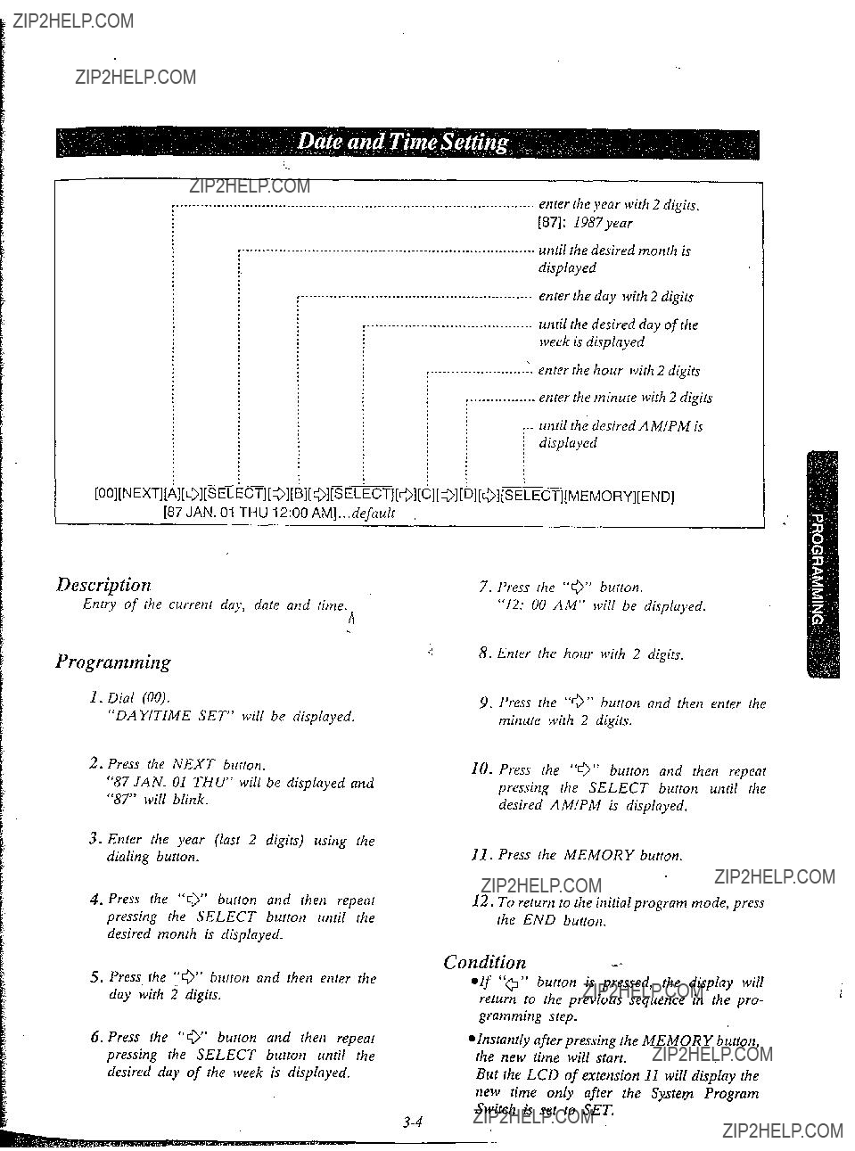
Description
Entry of the current day, date and time.
I!
Programming
1.Dial (00).
???DAMTIME SET??? will be displayed.
2.Press the NEXT button.
???87 JAN. 01 THU??? will be displayed and ???87??? will blink.
3.Enter the year (last 2 digits) using the dialing button.
5. Press- the ???0??? button and then enter the day with 2 digits.
7.Press the ???G??? button.
???12: 00 AM??? will be displayed.
10.Press the ???0??? button and then repeat pressing the SELECT button until the desired AM/PM is displayed.
Il. Press the MEMORY button.
12.To return to the initial program mode, press the END button.
desired day of the week is displayed.
@Instantly after pressing the MEMORY button, the new time will start.
But the LCD of extension I1 will display the new time only after the Systey Program Switch is set to SET.

r
tWJWP+W FiyJ[phone number][MEyORY][END]
1 AB=[OO]: speed accesscode 00
[99]: speed accesscode 99
CD=[ 91: nutotnatic line access number [81]: line accessnumber of CO 1
[86]: line accessnumber of CO 6.
Description
100 phone numbers each with up to 32 digits may be entered into programming for speed dialing use from each exretuion.
Pushing rhe
4.Enter the line access number.
9:for automatic selection
81:for CO 1
82:for CO 2
83:for CO 3
84:for CO 4
8.5: for CO 5
86: for CO 6
Programming
I.Dial (01) or press the A UT0 button to go inro the speed dialing entry mode.
???SPEED DIALING??? will be displayed.
2.Press the NEXT button.
???ENTER SPEED CODE??? will be displayed.
3.Dial (00 through 99) or press the NEXT burron, for speed access code entry. Example:
When dialing (00) or pressing the NEXT button.
aThe LCD will show ???0O:NOT STORED???
-when nothing is stored in speed access code ???00???. When the automatic line access num- ber 9 and the phone nutnber
5.Enter the phone number.
0 You may enter punctuations during a phone number.
@To erase a wrong entry, press the CLEAR button.
6.Press the MEMOBY burton.
@The memory indicator will be lit.
7.To program desired speed access code, press the SELECT button and then dial rhe speed access co&.
To advance to the next speed access code, press the NEXT bufton.
To return to the previous speed access code, press the PREV button.
:
i i
[
1 i
\
i:
1
1
1
I
L
8.Repeat steps 4 to 7.
9.To exit from speed dialing entry, press the END button.
eThe LCD will show .the initial program
mode, ???ENTER PGM CODE???.
To change
Repeat steps 1 to 9.
To erase after programming
1.Dial (01) or press the AUTO button. ???SPEED DIALING??? will be displayeci.
2.Press rhe SEXT button.
???ENTER SPEED CODE??? will be dis-
plaJ?ed.
:I:
3.Dial (00 throqiz 99) or press the NEXT butron, for speed access code entry.
The speed access code and the phone number will be displayed.
4.Press the CLEAR burton.
5.Press the MEMORY button
6.To program desired speed access code, press the SELECT blctton and then dial the speed access code.
To advance to the next speed access code, press the NEXT button.
Tti return to the previous speed access code, press the PREV button.
7.Repeat steps 4 to 6.
8.To exit from speed dialing entry, press the END
Conditions
l Use the ???+???I, or ???Q??? button for scrolling the display.
eThe line access number (9 or 81 through 86) should be stored.
o When dialing, the pause is automatically entered after line access number (9 or 81 through 86).
econtinuous use of speed dialing is possible. Example:
[AUTO] [Ol] [AUTO] [02]
In this case, speed access code ???02??? should not include the line access number.
There is a phone number directory on page

Examples
1) To enter line access number 81 and telephone number
aIf punctuations are not entered during a phone number, the LCD will show as below. (00: 812013924669)
2)To enter automatic line access number 9, account code 1234 and telephone number
4)To access ITT
(Q1 NEXT 02 8; 7654321 PAUSE PAUSE
Console 1 extension number
Telephone extension number paired with console 1
Console 2 extension number
EF=[12]: on extension 12
Telephone extension number paired with console 2
Y-
[02][NEXT]i,???r
. .

D&xription
If a DSS console is used the extension number paired with the DSS console should be assigned.
Programming
1.Dial (02)
???DSS CONSOLE SET??? will be displayed.
2.Press the NEXT button.
When console 1 has been stored to exten- sion 12, the pair telephone with the console 1 has been stored to extension 13, the console 2 has been stored to extension 14 and the pair telephone with console 2 has been stored to extension 15,
3.Dial the extension nlonber to which the console 1 is connected.
4.Press the ??? 0 ??? button.
5.Dial the extension number which is paired with the console 1.
???If you don???t connect the console 2, pro- ceed to step 10.
6.Press the ??? 0 ??? button.
7.Dial the extension number to which the console 2 is connected.
8. Press the ???I 0 ??? button.
9.Dial the extension number which is paired with the console 2.
10.Press the MEMORY button.
11.To return to the initial program mode, press the END button.
Conditions
l DSS console can be connected up to two. 0 DSS console can not be connected in pair wit
a standard telephone.
0 DSS console can not be connected at extensio
11.
Example:
If Mr Jay???s secretary has
Programming Table
See page
r
: ; .
[03] [NEXT] [w] [SELECT] [MEYORY] [END]
[03] [NEXT] [Al [SELECT] [MEMORY] [END]
A=*: to &sign the same on all 6 CO???s 1: 0nCOI
4.Press the SELECT button, to alternate be- tween CONNECT and NO CONNECT to select the desired mode.
5.Press the MEMORY button. The LCD
6.Repeat steps 3 to 5, to program the dialing mode on the other CO lines.
7.To return to the initial program mode, press the END button.
Programming Table
See page
[0orq][NEXT] [Al [SELECT] [MEMORY] [END]
pI???[+$]: to assign the same on all 6 CO???S
Description
Allows the user to select rhe dialing mode (tone or pulse) of each CO (Central Ofice) line. *TONE Dial Mode
The dial signal from rhe extension (ivith tone or pulse dial mode) will be converted to TONE. TONE will rhen be transmitted to the Cenrral Office.
l PlJLSE Dial Mode
The dial signal from rhe extension (with tone ot p&e dial mode) will be converted to PULSE. PULSE will then be transmitted to the Central Ofice.
Programming
1.Dial (04).
???CO DIAL MODE??? will be displayed.
2.Press the NEXT button.
???ENTER CO NO??? will be displayed.
3.Press the NEXT button.
???CO 1: TONE??? will be displayed and ???TONE??? will blink.
4.Press the SELECT button fo alternate be- tween TONE and PULSE.
5.Press the MEMORY butron.
6.Repeat sreps 3 to 5, to progratn the dialing mode on the other central ofice lines.
7.To return to rhe initial program mode. press the END burton.
Conditions
0 When you start the programming frotn step 1, you may dial rhe desired CO number instead of the NEXT button at step 3.
l The PREV button allows you to see the entry status in the previous CO dial mode.
???If the
???If your extension is not a
Example:
l TONE on the CO 1=
[04] [NEXT] [l] [MEMORY] [END]
or
[04] [NEXTJ [NEXT] [MEMORY] [END] *PULSE on the CO 2=
[04] [NEXT] [2] [SELECT] [MEMORY] [END] or
[04] [N&T] [NEXT] [NEXT] [SELECT] [MEMORY] [END]
Programming Table
See page

a.
:-
[05] [NEXT] [SE&CT] [MEMORY] [END]
Description
Allows DaylNight service to be selected manrtal- ly or automatically.
In case of manual switching, refer to ???Flexible Night Service??? page
In case of automatic switching, set the ???Starting Time (DaylNight Service)??? page
Programming .,
1.Dial (05).
???DAYINIGHT MODE??? will be displayed.
2.Press the NEXT button.
3.Press the SELECT button to alternate be- tween ???MAN??? and ???AUTO??? to select the desired mode.
4.Press the MEMORY button. The LCD
5.To return to the initial program mode, press the END button.
Conditions
When the Switching mode (Day/Night Service) is set to ???AUTO???, the present DaylNight Service mode will not change after you finish
programming. To change the present mode, I . manual operation is required.
After you selected the Starting time (DaylNight Service} page
:i
Programming Table
See page

[121 (O???cfock)
[59] (minute)
CPM
I . .
[+I (o???clock) . . . . . . . . . . . . default
[1???2] (o???clock)
D=[OO] (minute). . . . . . . . . . . . . . default [Ol] (minute)
[59] (minute)
/jzJr&q:. until the desired mode appears
[06][NEXT]-ECT][MEMORY][NEXT]
7 73
Description
If you select the automatic switching mode for daylnight service, enter the starting time. Refer to ???Switching Mode (DaylNight Service)??? page
Programming
1. Dial (06).
???DAY/NIGHT TIME??? will be displayed.
2. Press the NEXT button.
???DAY: 09:OO AM??? will be displayed as a default value and ???09??? will blink.
7.Press the SELECT button to alternate be- tween ???AM??? and ???PM??? to select the correct setting.
8.Press the MEMORY button.
9.Press the NEXT button.
???NIGHT: OS:00 PM??? will be displayed as a default value and ???05??? will blink.
10.Enter the starting time for night service using 2 digits.
11.Press the ???0??? button. ???00??? will blink.
12.Enter the minute using 2 digits.
13.Press the ???IQ??? button. ???PM??? will blink.
14.Press the SELECT button to ,alternate be- tween ???AM??? and ???PM??? to select the correct setting.
1s. Press the MEMORY button.
16.To return to the initial program mode, press the END button.
Conditions
elf the NEXT button is pressed at step 3 through 7, the display will advance to the ???Night Time input??? mode (step 9). The operations of step 3 through 7 are not stored. l if the PREV button is pressed at step IO through 14, the display will return to the ???day time input??? mode (step 2). The operations of
step 10 through 14 are not stored.
Example:
8.30 AM... starting time for day plan 6:30 PM. .. starting time for night plan
Programming Table
See page

Description
Through programming, you can select which extensions may be used for outward dialing by using the day mode of operation.
Programming
1.Dial (07).
???DAY: OUT CO??? will be displayed.
2.Press the NEXT button.
???ENTER EXT NO??? will be displayed.
3.Press the NEXT button.
???11: CO 12 3 4 5 6??? will be displayed and ???1 2 3 4 5 6??? will blink.
4.Dial the CO number to be entered.
The desired combination of CO lines will be displayed.
To prohibit dialing, press the CLEAR button instead of the CO number.
???11: CO.....??? will be displayed.
5.Press the MEMORY button. The LCD will stop blinking.
6.Repeat steps 3 to 5, to program the assign- ment on the other extensions.
7.To return to the initial program mode, press the END button.
Conditions
*When you start the programming from step 1, you may dial the desired
@The PREV button allows you to go to the previous extension for displaying the CO assignment.
Exanzple: COMPANY XYZ
Company XYZ wants only extension 11 and 15 to have access to CO 1, 2 and 3 on outgoing calls during the day. Extensions 12, 13, 14, 16, 17 and 18 are to be programmed for access to only CO 1 and 2.
1.[07] [NEXT] [(NEXT) or (ll)] [l] [2] [3] [MEMORY]
2.[NEXT] [I] [2] [MEMORY]
3.[NEXT] [l] [2] [MEMORY]
4.[NEXT] [l] [2] [MEMORY]
5.[NEXT] [l] [2] [3] [MEMORY]
6.[NEXT] [l] [2] [MEMORY]
7.[NEXT] [l] (21 [MEMORY]
8. [NEXT] fl] [2] [MEMORY] [END]
Programming Table
See page.
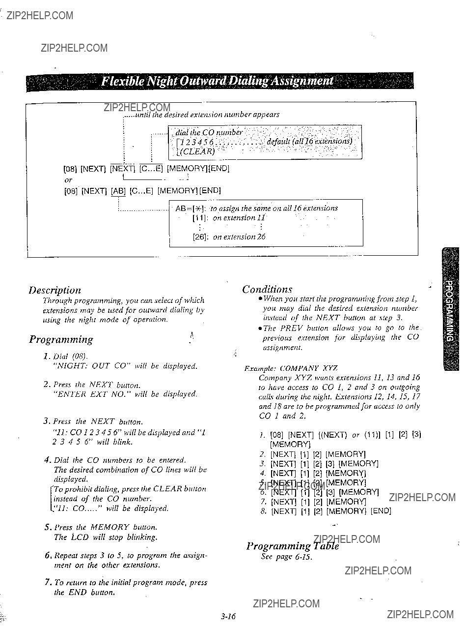
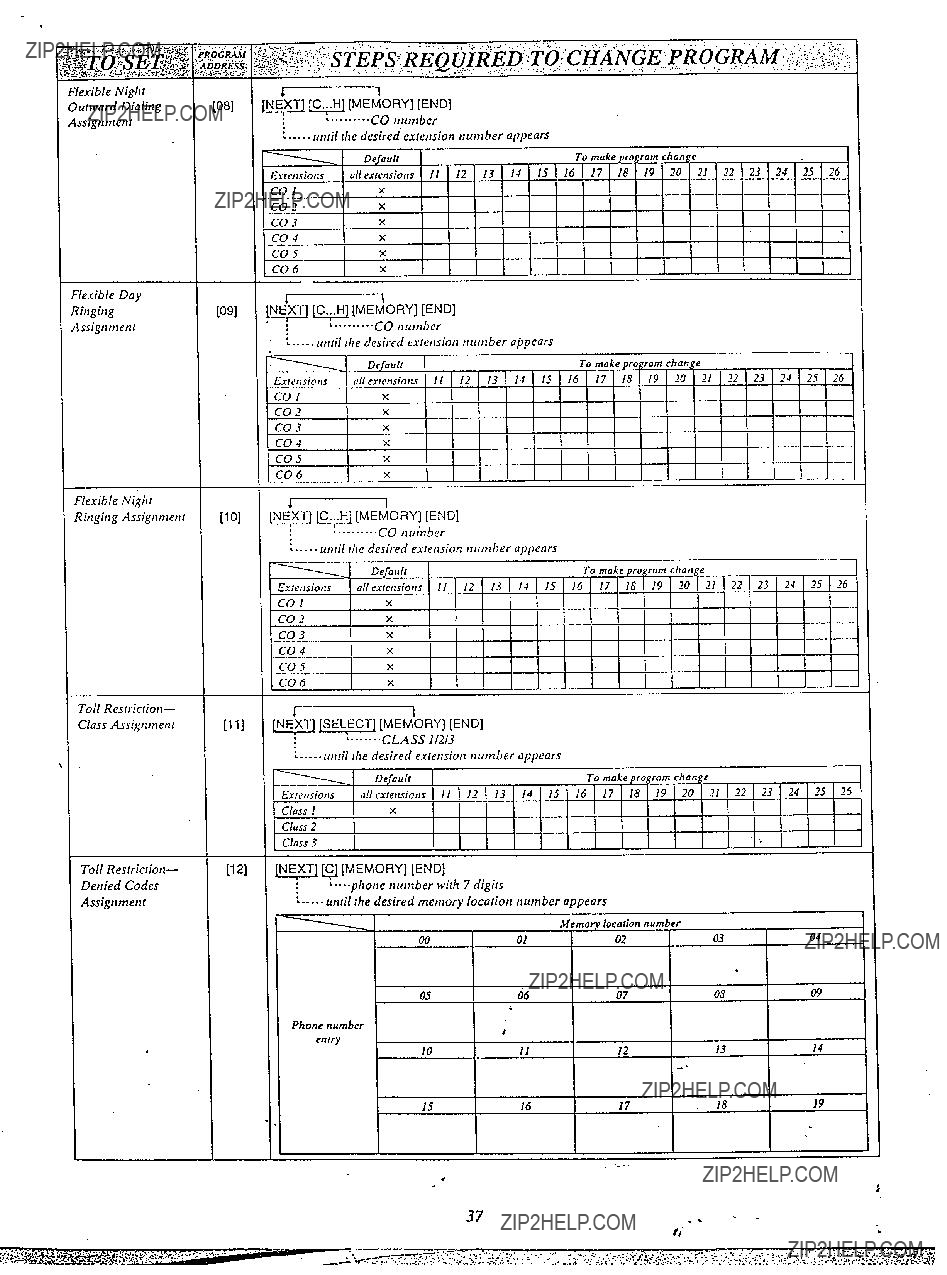
......until the desired extension number appears
[08] [NEXT] (N:XT] [C...El [MEM,ORY][END]
;8] [NEXT] [ABI [C...E] [MEMORY][END]
Description
to assign the same on all 16 extensions
Conditions
Through programming; you can select of which extensions may be used for outward dialing by using the night mode of operation.
Programmingn
:!
l When you start the programming from step 1, you may dial the desired extension number instead of the NEXT button at step 3.
l The PREV button allows you to go to the previous extension for displaying the CO assignment.
???11: CO 12 3 4 5 6??? will be displayed and ???1 2 3 4 5 6??? will blink.
4.Dial the CO numbers to be entered.
The desired combination of CO lines will be displayed.
To prohibit dialing, press the CLEAR button of the CO number.
???11: CO.....??? will be displayed.
5.Press the MEMO,RY button. The LCD
Example: COMPANY XYZ
Company XYZ wants extensions 11, 13 and 16 to have access to CO 1, 2 and 3 on outgoing calls during the night. Extensions 12, 14, 15, I7 and 18 are to be programmed for access to only CO 1 and 2.
1.[08] [NEXT] [(NEXT) or (ll)] [l] [2] (31 [MEMORY]
2.[NEXT] [l] [2] [MEMORY]
3.[NEXT] [l] [2] [3] [MEMORY]
4.[NEXT] [l] [2] [MEMORY]
5.[NEXT] [l] [2] [MEMORY]
6.[NEXT] [l] [2] [3] [MEMORY]
7.[NEXT] [I] (2) [MEMORY]
8.[NEXT] [l] [2] [MEMORY] [END]
6.Repeat steps 3 to 5, to program the assign- ment on the other extensions.
7.To return to the initial program mode, press the END button.
Programming Table
Seepage

Description
Through programming, you can select which extensions will ring on incoming calls from rhe Central Ofice during the day time.
Programming
1.Dial (09).
???DAY: IN CO??? will be displayed.
2.Press the NEXT button.
???ENTER EXT NO??? will be displayed.
3.Press the NEXT button.
???11: CO 1 2 3 4 5 6??? will be displayed and ???1 2 3 4 5 6??? will blink,
4.Dial the CO numbers to be entered.
The desired combination of CO lines will be displayed.
To prohibit ringing, press the CLEAR but- ton insread of the CO number.
I ???11: CO.....??? will be displayed.
5.Press the MEMORY button. The LCD will sfop blinking.
6.Repeat steps 3 to 5, to program the assign- ment on the orher extensions.
7.To return to the initial program mode, press the END button.
Conditions
0 When you start the programming from srep I, you may dial the desired extension number instead of the NEXT button at step 3.
eThe PREV button allows. you to go to the previous extension for displuying the CO assignment.
Exatnple:
Incoming calls from Central Ofice during the day are programmed to ritq at extension il
only.
1.[09] [NEXT] [++I [CLEAR] [MEMORY]
2.WEW[ll PI [31 [41 El PI
[MEMORY] [END]
Programming Table
See page
i..._........ .???dial the CO number 1???
:,(CLEAR)..
5.Press the MEMORY button. The LCD will stop blinking.
6.Repeat steps 3 to 5, to program the assign- ment of the other extensions.
7.TO return to the initial program mode, press the END button.
???i
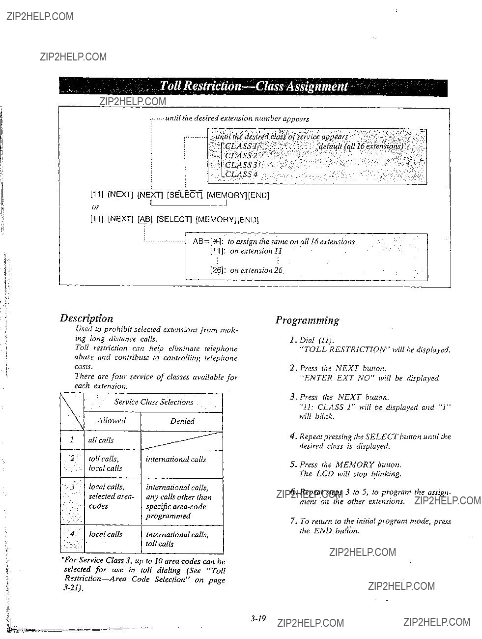
[ll][NEXT] [NEXT] [SELkTJ [MEMORYj[END]
;???1, [NEXT] [AB] [SELECTI [MEMORY][END]
Description
Use; to prohibit selected extensions from mak-
???For Service Class 3, up to 10 area codes can be selected for use in toll dialing (See ???Toll
Programming
1. Dial (II).
???TOLL RESTRICTION??? will be displayed.
2.Press the NEXT button.
???ENTER EXT NO??? will be displayed.
3.Press the NEXT button.
???11: CLASS 1??? will be displayed and ???1??? will blink.
4.Repeatpressiitg the SELECT button until the desired class is displayed.
5.Press the MEMORY button. The LCD will stop blinking.
6.Repeat steps 3 to 5, to program the assign- ment on the other extensions.
7.To return to the initial program mode, press the END b&n.

Conditions
l When you start the programming from step 1, you may dial the desired extension number instead of the NEXT button at step 3.
@The PREV button allows you to go to the previous e.utension for displaying the service class assignment.
l In some areas a ???1??? is needed before dialing tht area code for long distance call. If your area does not need to dial a ???I???, the Programmable Toll Prefix should be set to ???WITHOUT 1???.
Refer to ???Programmable Toll Prefix??? page
Example:
l To prohibit international calls on extension 13 but allow local and toll calls enter.
[ll][NEXT] [13] [SELECT] [MEMORY].
ENDI
;I, [NEXT] [NEXT] [NEXT] [NEXT] [SELECT] [MEMORY] [END]
l To prohibit international calls and toll calls on extension 14 but to allow local calls.
[Ill [NEXT] [14] [SELECT] [SELECT] [SELECT] [MEMORY](END]
or
[ll] [NEXT] [NEXT] [NEXT] [NEXT] [NEXT] [SELECT] [SELECT] [SELECT] [MEMORY] [END]
Programming Table
See page

[12][NEXTI[*~][C][MEMORY][END]
Description
Programming
When Service Class 3 is programmed;
1.Dial (12).
???CLASS 3 AREA CODE??? will be display- ed.
2.Press the NEXT button.
???ENTER CODE NO.??? will be displayed.
3.Dial (00 through 09) or press the NEXT button.
Example:
When dialing (00) or pressing the NEXT button.
aThe LCD will show ???0O:NOT STORED??? wh?n nothing is stored in memory location number ???00???.
When area code 212 has been stored, ???00:212??? will be displayed.
4.Dial the area code, with 3 digits.
@To erase a wronx entry, press the CLEAR button.
5.Press the MEMORY button.
@The memory indicator will be lit.
6.To advance to the .next memory location number, press the NEXT button.
To return to the previous memory location number, press the PREV button.
To go to the desired memory location num- ber, press SELECT button and the dial the memory location number.
7.Repeat steps 4 to 6.
8.To return to the initial program mode, press the END button.
Example:
To allow extension 12 to have access to New York City and the entire state of New Jersey, program the following.
New York City has 2 area codes 212, 718 and New Jersey 201, 609.
Enter 212 into the memory locntion number ???OO???, 718 into ???Ol???, 201 into ???02??? and 609 into
???03???.
STEP l...[ll]
[SELECT] [MEMORY] [END]
STEP 2...[12][NEXTltNEXTl[212][MEMORY] [NEXTj[718][MEMORY] [NEXT)[201][MEMORY] [NEXTj[609][MEMORY][END]
Programming Table -
See page

until the desired mode appears
[13] [NEXT] [SELECT] [MEMORY] [END]
Description
Set to ???WITH 1??? for Toll Restriction in areas where you are required to dial 1 to toll calls (long distance).
Example:
You are required to insert a ???1??? before di@ling the area code for long distance calls. .
Set to ???WITHOUT 1??? in area where a ???1??? is not needed.
Programming
1.Dial (13).
???TOLL PREFIX??? will be displayed.
2.Press the NEXT button.
???WITH 1??? will be displayed and blink.
3.Press the SELECT button to alternate between ???WITHOUT I??? and ??? WITH 1??? to select the desired mode.
4.Press the MEMORY button.
The LCD will stop blinking.
5.To return to the initial program mode, press the END button.

[14] [NEXT] [NEi(T] [SELkCT] [MEMORY] [END]
ort
[l4] [NEXT] [AB] [SELECT] [MEMORY] [END]
7
???AB=[%]: to assign the same on all 16 extensions
Description
Through programming, you can select of which extensions may dial an Operator Call.
To deny all dialing that starts from ???O???, set to
DISABLE.
Programming
1.Dial (14).
???OPERATOR CALL??? will be displayed.
2.Press the NEXT button.
???ENTER EXT NO??? will be displayed.
3.Press the NEXT button.
???11: ENABLE??? will be displayed and ???ENABLE??? will blink.
4.Press the SELECT button, to alternate be- tween ENABLE and DISABLE to select the desired mode.
5.Press the MEMORY button. Tha LCD will stop blinking.
6.Repeat steps 3 to 5, to program the assign- ment of the other extensions.
7.To return to the initial program mode, press the END button.
Conditions
0 When you start the programming from step 1, you may dial the desired extension number instead of the NEXT button at step 3.
l The PREV button allows you to go to the previous extension for displaying the operator call selection.
*Operator call dialing can not be denied if service class 1 of Toll Restriction is used.
Example:
0 To prohibit operator call on extensiotl I2
[14] [NEXT] 1121 [SELECT] [MEMORY] IEND]
Programming Table
See page

......:...._________________________
Description
Through programming, you can select which extensions may be dialed Directory Assistance ???411???. For to deny the directory assistance dialing, set to RESTRICT.
n
Programming
1.Dial (1.5).
???DIRECTORY ASSIST??? will be displayed.
2.Press NEXT button.
???NO RESTRICT??? will be displayed and blink,
3.Press the SELECT button to alternate be- tween ???NO RESTRICT??? and ???RESTRICT???
to select the desired mode.
4.Press the MEMORY button. The LCD will stop blinking.
5.To return to the initial program mode press the END button.
Conditiorts
Example:
o To prohibit directory assistance.
[15][NEXT][SELECT][MEMORY][END]
Programming Table
See page
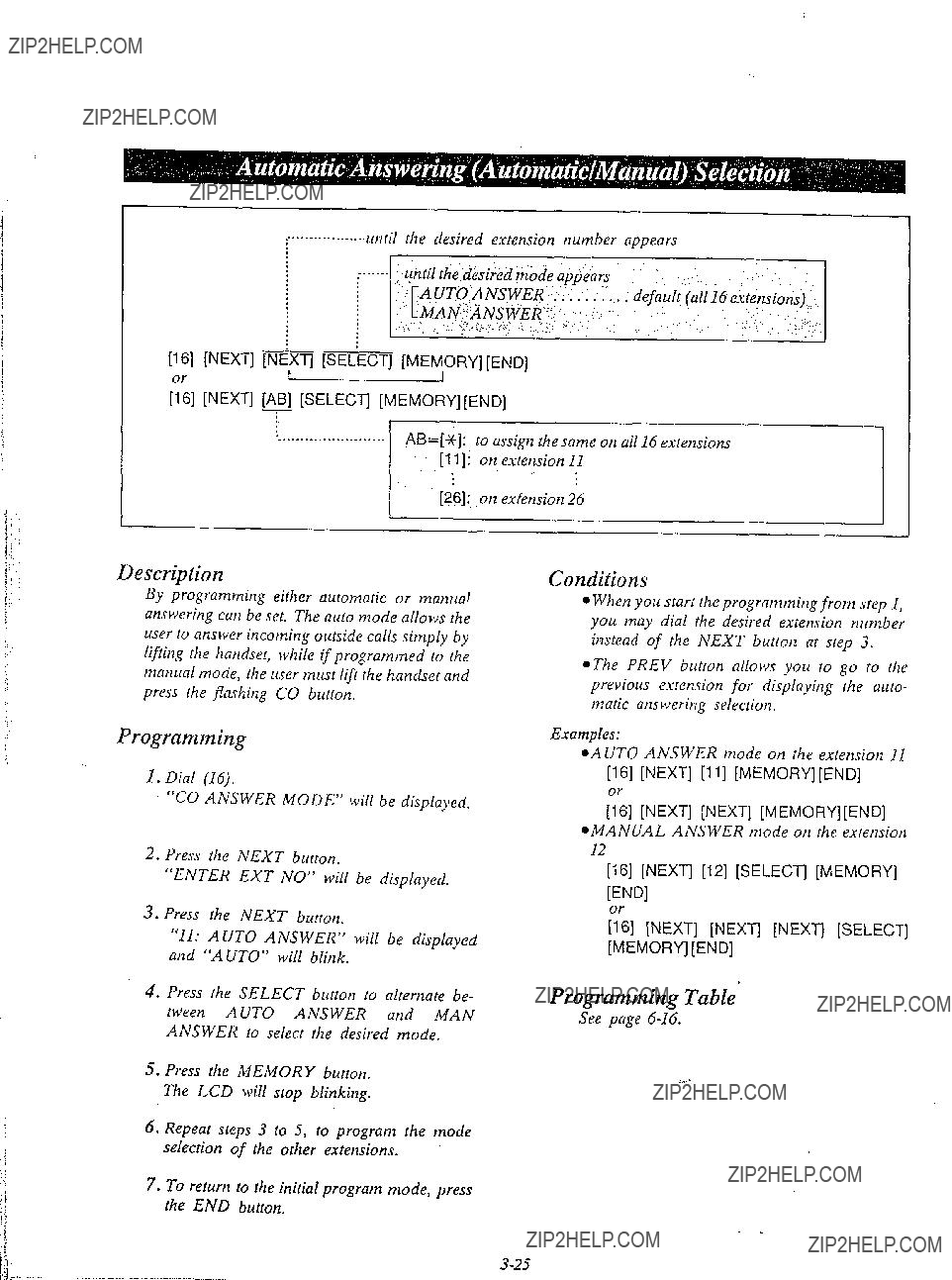
[16] [NEXT] [NEXT] [SELECT] [MEMORY][END] t
[:;I [NEXT] [ABI [SELECT] [MEMORY][END]
Description
By programming either automatic or manual answering can be set. The auto mode allows the user to answer incoming outside calls simply by lifting the handset, while if programmed to the manual mode, the user must lift the handset and press the flashing CO button.
Programming
I. Dial (IS).
???CO ANSWER MODE??? will be displayed,
2.Press the NEXT button.
???ENTER EXT NO??? will be displayed.
3.Press the NEXT button.
???11: AUTO ANSWER??? will be displayed and ???AUTO??? will blink.
4.Press the SELECT button to alternate be- tween AUTO ANSWER and MAN ANSWER to select the desired mode.
5.Press the MEMORY button. The LCD will stop blinking.
6.Repeat steps 3 to 5, to program the mode selection of the other extensions.
7.To return to the initial program mode, press the END button.
Conditions
e When you start the programming from step 1, you may dial the desired extension number instead of the NEXT button at step 3.
*The PREV button allows you to go to the previous extension for displaying the auto- matic answering selection.
Examples:
l AUT0 ANSWER mode on the extension 11
[16] [NEXT] [I 11 [MEMORY] [END]
,3:] [NEXT] [NEXT] [MEMORY][ENDl
*MANUAL ANSWER mode on the extension I2
[16] [NEXT] [12] [SELECT] [MEMORY]
[END1
&I [NEXT] [NEXT] [NEXT] [SELECT] [MEMORY] [END]
Programming Table
See page

;;] [NEXT] [A] [A... D] [MEMORY][END]
._________._____.___.. A=[*]:... to assigll the same on all 6 CO???s
i
Description
If the system,
7.To return to the initial program mode, press the END button.
Programming
1.Dial (17).
???HOST PBX ACCESS??? will be displayed.
2.Press the NEXT button.
???ENTER CO NO??? will be displayed.
3.Press the NEXT button.
*The LCD will show ???COl: NOT STORED??? when nothing is stored in COI. When the outside access codes 81, 82 has been stored, ???CO1:81, 82??? will be display- ed.
4.Enter vp to four outward access codes each with a maximum of 2 digits, punctuating each code with the r;l button.
l To erase a wrong entry, press the CL EAR button.
5. Press the MEMORY button.
Conditions
0 When you start the programming from step 1, you may diai the desired CO number instead of the NEXT button at step 3.
l The PREV button allows you to go to the previous CO for displaying the host PBX access codes assignment.
Example:
@Access codes 81, 82, 83, 9 on CO1 =
1171
[MEMORY] [END]
or
V71 [NEXT1 [NEXT] Pll Ll WI Ll F331 LI PI
[MEMORY] [END]
Programming
See page

[18] [NEXT] INEkT] [SE<ECT] [MEMYRY] [END]
or
[18] [NEXT] [ABI [SELECT] [MEMORY] [END]
i
Description
When any itlcoming ctrlls from the Central Office are recei\*ed at the same time, you can receive the call on the preferred CO line first.
Programming
I.Dial (18).
???PREFERRED CO??? will be displayed.
2.Press the NEXT button.
???ENTER EXT NO??? will be displayed.
3.Press the NEXT button.
4.Repeat pressing the SELECT button until the desired CO number is displayed.
5.Press the MEMORY button. The LCD will stop blinking.
6.Repeat steps 3 to 5, to program the assign- ment of the other extensions.
7.To return to the initial program mode, press the END button.
Conditions
l When you start the programming from step 1, you may dial the desired extension number instead of the NEXT button at step 3.
OThe PREV button allows you to go to the previous extension for displaying the preferred CO line assignment.
Programming Table
Seepage
- _
Description
During a conversation, a call waiting tone will be heard when a third party on an outside line or intercom calls you.
Call waiting tone can be removed or add!d at customer???s request.
Set to ???ON??? for call waiting.
5.Press the MEMORY button. The LCD will stop blinking.
6.Repeat steps 3 to 5, to program the assign- ment of the other extensions.
7.To return to the initial program mode, press the END button.
Programming
1.Dial (19).
???CALL WAITING??? will be displayed.
2.Press the NEXT button.
???ENTER EXT NO??? will be displayed.
3.Press the NEXT button.
???11:
4.Repeat pressing the SELECT button until the desired mode is displayed.
Conditions
e When you start the programming from step 1, you may dial the desired extension number instead of the NEXT button at step 3.
@The PREV button allows you to go to the previous extension for displaying the call waiting selection.
Programming Table -
See page
AI
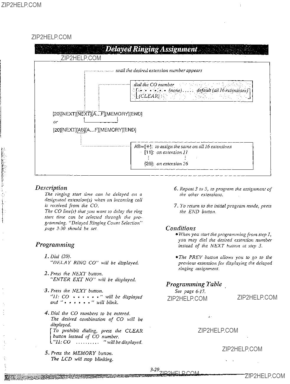
[20][NEXT][NEXT][A...F][MEMORY][END]
Description
The ringing start time can be delayed on a designated extension(s) when an incoming call is received from the CO.
The CO line(s) that you want to delay the ring start titne can be selected through the pro- gramming. ???Delayed Ringing Count Selection??? page
Programming
1.Dial (20).
???DELAY RING CO??? will be displayed.
2.Press the NEXT button.
???ENTER EXT NO??? will be displayed.
3.Press the NEXT button.
???11: CO 8 8 l l l l ??? will be displayed
and ??? l l l l l l ??? will blink.
4.Dial the CO numbers to be entered.
The desired combination of CO will be displayed.
To prohibit dialing, press the CLEAR button instead of CO number.
???11: CO . . . . . . . . . . ??? will be displayed.
5.Press the MEMORY button. The LCD will stop blinking.
.??? .I
6.Repeat 3 to 5, to program the assignment of the other extensions.
7.To return to the initial program mode, press the END button.
Conditions
0 When you start the programming from step P, you may dial the desired extension number instead of the NEXT button at step 3.
eThe PREV button allows you to go to the previous extension for displaying the delayed ringing assignment.
Programming Table ,
See page

i
[21][NEXT][SEI LIECT][MEMORY][END]
Description
After you select the CO lines that you want to delay the ring start time, select the desired delay ring count. Refer to ???Delayed Ringing Assign- merit??? page
Programming
1. Dial (21).
???DELAY RING COUNT??? will be dis- played.
2.Press the NEXT button.
???AFTER 2 RINGS??? will be displayed and will blink.
3.Repeat pressing the SELECT button until the desired mode is displayed.
:I
4.Press the MEMORY button. The LCD will stop blinking.
5.To return to the initial program mode, press the END button.
Programming Table
See page
,.........__ unril the desired extension number appears
,???r.???::_ !
default (all 16 extensions)
Description
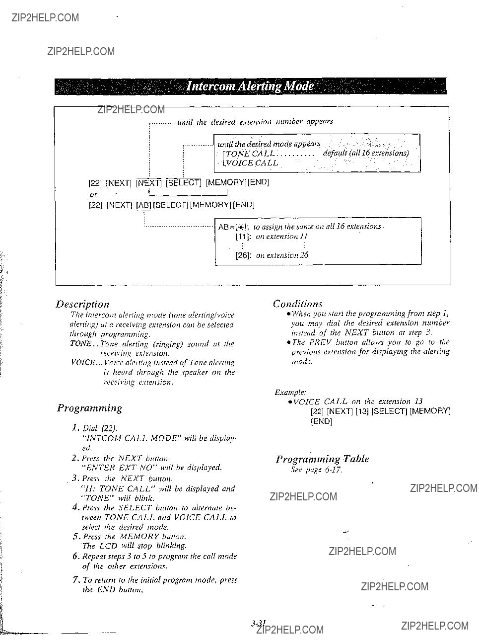
The inrercotn alerting mode (tone alertinglvoice alerting) ar a receiving extension can be selected rhrough programming.
TONE. . Tone alerting (ringing) sound at the recei\*itlg esrension.
VOICE.. . Voice alerrittg instead of Tone alerting is
Prograrnrnirzg
1.Dial (22).
???INTCOM CALL MODE??? will be display- ed.
2.Press the NEXT burron.
???ENTER EXT NO??? will be displayed.
3.Press the NEXT button.
???11: TONE CALL??? will be displayed and ???TONE??? will blink.
4.Press rhe SELECT button lo al!ernare be- tween TONE CALL and VOICE CALL 10 select rhe desired mode.
5.Press the MEMORY button.
6.Repear sreps 3 10 5 to program rhe call mode of rhe other extensions.
7.To return to the initial program mode, press the END burron.
Conditions
l When you start the programming frotn step 1, you may dial the desired extension number instead of the NEXT button at step 3.
l The PREV button allows you to go to rhe previous extension for displaying the alerting mode.
Example:
l VOICE CALL on the extension 13
[22] [NEXT] [13] [SELECT] [MEMORY]
WDI
Prograkning Table
See page
:
I
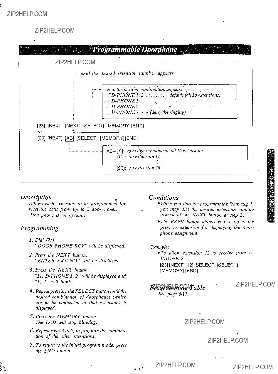
until the &sired combination appears
1 j
[23] [NEXT] F [SELECT] [MEM,ORY][END]
;3] [NEXT] [AB] [SELECT] [MEMORY] [END]
,________________.__AB=[G+]:. to assign the same on all 16 extensions [l I]: on extension 11
[26]: on extension 26
Description
Allows each extension to be programme??? fl for receiving calls from up to 2 doorphones. (Doorphone is an option.)
Programming
1.Dial (23).
???DOOR PHONE RCV??? will be displayed.
2.Press the NEXT button.
???ENTER EXT NO??? will be displayed.
3.Press the NEXT button.
???11:
4.Repeat pressing the SELECT button until the desired combination of doorphones (which are to be connected to that extension) is displayed.
5.Press the- MEMORY button. The LCD will stop blinking.
6.Repeat steps 3 to 5, to program the combina- tion of the other extensions.
7.To return to the initial program mode, press the END button.
Conditions
l When you start the programming from step 1, you may dial the desired extension number instead of the NEXT burton at step 3.
*The PREV button allows you to go lo the previous extension for displaying rhe door- phone assignment.
Example:
*To allow extension 12 to receive from D-
PHONE 2
[23] [NEXT] [12] [SELECT] [SELECT] [MEMORY] [END]
Programming Table *
See page

Description
Pertnits an extension user fo answer othet ringing telephones, provided that they are in the same pickup group.
6.Repeat steps 3 10 5, to program the assign. men1 of fhe other exretisions.
7.To relrcrti lo the initial program mode, press the Eh???D burron.
Programming
1.Dial (24).
???PICKUP GROUP??? will be displayed.
2.Press rhe NEXT burron.
???ENTER EXT NO??? will be displayed.
3.Press rhe NEXT burton.
???11: PKG: 1??? will be displayed and ???1??? will blink. This means that extension 11 belongs to pickup group 1.
4.Dial the pickup group number (1 through 4) to be entered.
The desired combination of pickup group will be displayed.
To
5.Press the MEMORY button. The LCD will stop blinking.
Conditions
peach extension may belong to more than one pickup group, up to four, or tnay nof belong to a group.
l When you start the programming from step 1, you may dial the desired extension numbet instead of the NEXT button at step 3.
.The PREV buuon allows you IO go fo rhe previous extension for displaying rhe pickup
group assignment. *
Examples:
l extension 14.. Jickup Group 2 [24][NEXT][14][2][MEMORY][END]
*extension 15...Pickup Group 3 [24](NEXTj[15][3][MEMORY][END]

j____.__.____...... until the desired extension number appears
1
/
[*5][NEXT]pipsELECT][MEMyY][END]
OY
[25][NEXT][AB][SELECT][MEMORY][END]
7
Description
This feature gives each message of the SMDR an account code of the called or calling party. ..
This feature has two modes ???FORCED??? and ???OPTION???. In the ???FORCED??? mode, the account code must be entered every time exten- sion user dials.
In the ???OPTION??? mode, the account code may be entered when a record is needed. Refer to ???Account Code??? page
to assign the same on all 16 extensions
5.Press the MEMORY button. The LCD will stop blinking.
6.Repeat steps 3 to 5, to program the account code of the other extensions.
7.To return to the initial program mode, press the END button.
Programming
1.Dial (25).
???ACCOUNT CODE MOD??? will be display- ed.
2.Press the NEXT button.
???ENTER EXT NO??? will be displayed.
3.,?ress the NEXT button.
???11: OPTION??? will be displayed and the ???OPTION??? will blink.
4.Press the SELECT button to alternate be- tween OPTION and FORCED to select the desired mode.
Conditions
l When yore start the programming from step 1, you may dial the desired extension number instead of the NEXT button at step 3.
*The PREV button allows you to go to the previous extension for displaying the account code input mode.
Programming Table

[26] [NEXT] [SELECT] [MEMORY)[END]
Description
The duration time of the conversation is dis- played.
Program the start time of the timer. oInstantly after the CO line is captured. 05 seconds after the dialing
*IO seconds after the dialing
Example:
10 seconds after the dialing
=[26] (NEXT] [SELECT] [MEMORY] [END]
Programming Table ???.
See page
Programming
1 s Dial (26).
l
2.Press the NEXT button.
~??????5s AFTER DIAL??? will be displayed and blink.
3.Repeat pressing the SELECT button until the desired time (INSTANTLY, 5s AFTER DIAL, 10s AFTER DIAL) is displayed.
4.Press the MEMORY button. The LCD will stop blinking.
5.To return to the initial program mode, press the END button.
Description
SMDR is a cost saving feature that records on a printer a record of all incoming and outgoing calls. The following information is provided on the printout.
The SMDR will print out the security code of the long distance service. (MCI, SPRINT etc.)
NOTE:
When plugging a printer into the
Select the SMDR Communication Parameters, System Data Dump and SMDR IncominglOutgoing Selection for proper operation.
Example of print
(Carriage return for a new line)
until the desired code appears
[*7][NEXT][sEL~cT][MEMORY] 1
(Baud rate)
until the desired baud rate appears
-
Proceed to page
J

. .default
-[NEXT][SE&CT][MEMORY]
(Stop bit length)
i.___________........:......... ....y\until the desired mode appears
-[NEXT][SE&CT][MEMORY] 1
(Page length)
(Skip perforation)
AB=[O] (line). . ; : default
A new line code indicates what type of code is needed for the print head on a printer to move the first character position on the next line.
CR= Carriage Return
LF= Line Feed.
A baud rate code indicates the data transmission speed from the system to a printer.
The default value is the same as that of the Panasonic data terminal,
A parity code indicates what type of parity is used to detect an error in a string of bits composing a character.
NONE: when an error checking function is not required from a printer.
MARK: when a Mark is required from a printer.
SPACE: when a Space is required from a printer.
EVEN: when an Even is required from a printer.
ODD: when an Odd is required from a printer.
A word length code indicates how many bits compose a character.
7 BITS (when 7 bits are required.)
8 BITS (when 8 bits are required.)
A stop bit length code indicates the end of a bit string which composes a character.
1 BIT:
when one bit is required for end detection.
2 BITS:
when two bits are required for end detection.
The page length may be selected to position a title and data on each page.
A page length code indicates the number of lines per page.
A title will be printed on the first 3 lines of each page.
<I
STANDARD CONTINUOUS PAPER (11 inches)
we
To print data, page length must be longer than skip perforation by 4 or more liries.
The skip perforation code indicates the number of lines to be skipped. When the print head reaches the line designated, the print head moves to the top position of the next page.
0 (print head does not skip.)
1 (print head skips the last line.)
2 (print head skips the last 2 lines.)
9; (print head skips the last 95 lines.)
Programming
I. Dial (27).
???SMDR PARAMETERS??? will be dis- played.
2.Press the NEXT button.
3.Press the SELECT button to alternate between
4.Press the MEMORY button. The LCD will stop blinking.
5.Press the NEXT button.
???BAUD RATE: 1200B??? will be displayed and the ???1200B??? will blink.
6.Repeat pressing the SELECT button until the desired baud rate is displayed.
7.Press the MEMORY button. The LCD will stop blinking.
8.Press the NEXT button.
???WORD LENGT: 7BITS??? will be dis-
played and the ???7BIT.S??? will blink.
9. Press the SELECT button to alternate between 7BITS and 8BITS to select the
10.Press the MEMORY button. The LCD will stop blinking.
11.Press the NEXT button.
???PARITY: MARK??? will be displayed and the ???MARK??? will blink.
12.Repeat pressing the SELECT button until the desired parity code is displayed.
13.Press the MEMORY button. The LCD will stop blinking.
14.Press the NEXT button.
???STOP BIT: IBIT??? will be displayed and
the ???IBIT??? will blink.
15.Press the SELECT button to alternate between 1BIT and ZBITS to select the desired mode.
16.Press the MEMORY button.
The LCD will stop blinking.
17.Press the NEXT button.
???PAGE LENGTH: 66??? will be displayed and the ???66??? will blink.
18.Dial (4 through 99) for the page length entry.
19.Press the MEMORY button. The LCD will stop blinking.
20.Press the NEXT button.
???SKIP PERF: 0??? will be displayed and the ???0??? will blink.
21.Dial (0 through 95) for the skip perfora- tion code entry.
22.Press the MEMORY button. The LCD will stop blinking.
23.To return to the initial program mode, press the END button.
Programming Table
See page
Conditions _???
~To return to the previous mode, press the PREV button instead of the NEXT button.

Conditions
The following combinations are disallowed.
stop bit length
If any of the above disallowed combinations are selected, ???INPUT ERROR??? will be displayed. Press the NEXT button and then repeat the procedure of programming.
The pin conJguration of EZA
EIA SIGNALS:
Frame Ground (FG);
Connects to the unit frame and the earth ground conductor of the AC power cord.
Transmitted Data (TXD); . . . . . . . . . . . . . . (output) Conveys signals from the unit to the printer. A ???MARK??? condition is held unless data or BREAK signals are being transmitted.
Received Data (RXD); . . . . . . . . . . . . . . . . . . . . (input)
Conveys signals from the printer.
Request To Send (RTS); . . . _. . . . . . . . . . . . (output) This lead is held ON whenever DSR is ON.
Clear To Send (CTS); . . . . . . . . . . . . . . . . . . (input) An ON condition of circuit CTS indicates that the
printer is. ready to receive data frotn the unit. A The unit does not attempt to transfer data or receive
data when circuit CTS is OFF.
Data Set Ready (DSR); . . . . . . . . . . . . . . . . . . (input) An ON condition of circuit DSR indicates the Iprinter is ready.
???Circuit DSR ON does not indicate that communica- tion has been established with the printer.
Signal Ground (SG);
Connects to the DC ground of the unit for all interface signal.
Data Terminal Ready (DTR) . _. . . . . . . . . . (output) This signal line is turned ON by the unit to indicate that it is ON LINE.
Circuit DTR ON does not indicate that communica- tion has been established with the? printer.
It is switched OFF when the unit is OFF LINE.
Data Carrier Defect (DCD) . . . . . . . . . . . . . . . . (input) The ON condition is an indication to data terminal (DTE) that the carrier si@al is being received.

*STOP OUTPUT
[28][NEXT][SELiCT][MEMORY][END]
*SYSTEM PARA aSPEED DIAL
*ALL PARA (Master)
[28][NEXT][SE t
: STOP OUTPUT
[28][NEXT][SELkT][MEMORY]&END]
l EXT PARA
[28] [NEXT][SEl
Description
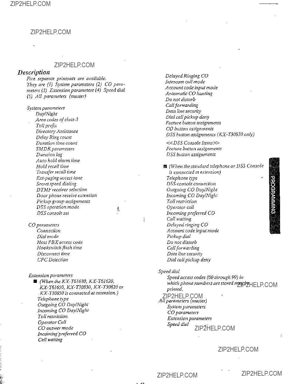
Five separate printouts are available.
They are (1) System parameters (2) CO para- meters (3) Extension parameters (4) Speed dial
(5) All parameters (master)
System parameters DaylNight
Area codes of
Directory Assistance Delay Ring count Duration time count SMDR parameters
Duration log
Auto hold alarm time Hold recall time Transfer recall time
D TMF receiver selection Door phone receive extension Pickup group assignments
DSS operation moden DSS console set
CO parameters
Connection
Dial mode
Host PBX access code
Hookswitch flash time
Disconnect time
CPC Detection
Extension parameters
q (When the
KX- T&650, KX- T30830, KX- T30820 or
Outgoing CO DaylNight
Incoming CO Day/Night Toll restriction
Operator Call CO answer mode
Incoming preferred CO Call waiting
Delayed Ringing CO Intercom call mode Account code input mode Automatic CO hunting Do not disturb
Call forwarding Data line security
Dial callpickup deny Feature button assignments CO button assignments
DSS button assignments
<< DSS Console Items>> Feature burton assignments DSS button assignments
H (When thestandard telephone or DSS Console is connected at extension)
Telephone typeJ DSS console connection
Outgoing CO DaylNight
Incoming CO Day/Night Toll restriction
Operator call
Incoming preferred CO Call waiting
Delayed ringing CO Account code input mode Pickup dial
Do not disturb Call forwarding Data line security
Dial call pickup deny
Speed dial
Speed access codes (00 through 99) in which phone numbers are stored may be printed.
Operation
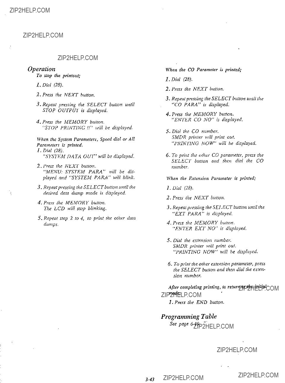
To stop the printout;
1.Dial (28).
2.Press the NEXT button.
3.Repeat pressing the SELECT button until STOP OUTPUT is displayed.
4.Press the MEMORY button.
???STOP PRINTING !!??? will be displayed.
When the System Parameters, Speed dial or All Parameters is printed.
I.Dial (28).
???SYSTEM DATA OUT??? will be displayed.
2.Press the NEXT button.
???MENU: SYSTEM PARA??? will be dis-
played and ???SYSTEM PARA??? will blink.
3.Repeatpressing the SELECT button until the desired data dump mode is displayed.
4.Press the MEMORY button. The LCD will stop blinking.
5.Repeat step 2 to 4, to print the other data dumps.
When the CO Parameter is printed;
1.Dial (28).
2.Press the NEXT button.
3.Repeat pressing the SELECT button until the ???CO PARA??? is displayed.
4.Press the MEMORY button. ???ENTER CO NO??? is displayed.
5.Dial the CO number.
SMDR printer will print out. ???PRINTING NOW??? will be displayed.
6.To print the other CO parameter, press the SELECT button and then dial the CO number.
When the Extension Parameter is printed;
1.Dial (28).
2.Press the NEXT button.
3.Repeat pressing the SELECT button until rlze ???EXT PARA??? is displayed.
4.Press the MEMORY button. ???ENTER EXT NO??? is displayed.
5.Dial the extension number. SMDR printer will print out.
???PRINTING NOW??? will be displayed.
6.To print the other extension parameter, press the SELECT button and then dial the exterz- sion number.
After completing printing, to return to the initial mode;
1. Press the END button.
Programming Table
See page
until the desired mode appears
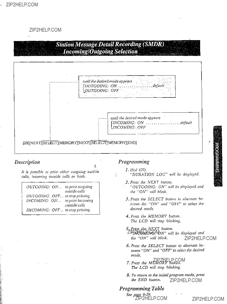
Description
n
It is possible to print eithe; outgoing out&de calls, incoming outside calls or both.
Programming
3.Press the SELECT button to alternate be- tween the ???ON??? and ???OFF??? to select the desired mode.
4.Press the MEMORY button. The LCD will stop blinking.
5.Press the NEXT button.
???INCOMING: ON??? will be displayed arid the ???ON??? will blink.
6.Press the SELECT button to alternate be- tween ???ON??? and ???OFF??? to select the desired
mode.-L
7???. Press the MEMORY button. The LCD will stop blink@.
8.To return to the initial program mode, press the END button.
Programming Table

until the desired time appears
[30] [NEXT] [SE<ECT] [MEMORY] [END]
Description
A tone itldication will be heard at the holding extension to remind the user that he still has a call on hold.
The reminder will sound after 3 minutes but can be changed.
There are 9 choices ranging from (1) minute to
(9).
4. Press the MEMORY button. The LCD will stop blinking.
5.To return to the initial program mode, press the END button.
Conditions
Progmmming
1.Dial (30).
???AUTO HOLD ALARM??? will be display- ed.
2.Press the NEXT button.
???TIME: 3 MIN??? will be displayed and ???3??? will blink.
3.Repeat pressing the SELECT brcttotl until the desired time is displayed.
The hold time reminder is activated, even if the hold recall time set is programmed to ???DIS- ABLE???.
Example:
4 minutes= [30] [NEXT] [SELECT] [MEMORY] [END]
Programming Table
See page

until the desired time appears ???
:
[31] [NEXT ???1[SELECT] [MEMORY] [END]
Description
When the handset of the holding extension is replaced back on call, you may have the automatic hold recall after the desired time elapses.
The hold recall titne set can be removed ot added at the customer???s request.
Programming
1. Dial (31).
Example:
I.5 minutes: [31] [NEXT] [SELECT] [SELECT] [MEMORY] [END]
Programming Table
See page
2.Press the NEXT button.
???TIME: 30 SEC??? will be displayed and ???30 SEC??? will blink.
3.Repeat pressing the SELECT button until the
desired time (30 SEC, 1 MIN, 1.5 MIN, 2 MIN, DISABLE) is displayed.
4.Press the MEMORY button. The LCD will stop blinking.
5.To return to the initial program mode, press the END button.

[32] [NEXT] [SELECT] [MEMORY]
Description
The acktloj\)leti,oe four rhar is heard nfrer ncces- sitlg Ilie external pagitlg cat1 be retnol~ed ot added ciI rlie cusIot?ier???s request.
until the,&sired mode appt&
[END]
Example:
To elitninare rhe paging access tone. [32] [NEXT] [SELECT] [MEMORY][END]
Programming Table
See page
2.Press the NEXT butrorl,
???ENABLE??? will be displayed and blitzk.
3.Press the SELECT burron to altertrare be- fweetl ENA B L E arid DISA B LE IO selecr rile desired mode.
4.Press the MEMORY burrotl. The LCD will stop blinking.
5.To return to rile initial program mode. press tile END burton.
[33] [NEXT] [SELECT] [MEMORY] [END]
3escription
When you dial on an outside line by speed dialing, the dialed number can be kept secret by not being displayed.
(The dialed number will not be displayed on the LCD of the
h
Programming
1.Dial (33).
???SECRET SPEEDDIAL??? will be dis-
played.
2.Press NEXT button.
???NO SECRET??? will be displayed and blink.
3.Press the SELECT button to alternate between ???NO SECRET??? and ???SECRET??? to select the desired mode.
4.Press the MEMORY button. The LCD will stop blinking.
5.To return to the initial program mode, press the END button.
Programming Table *
See page

until the desiredflash timing appears
:.
[34] [NEXT] [NEI(T] [SELECT] [MEMYRY] [END] or
[34] [NEXT] [A] [SELECT] [MEMORY] [END]
Description
The timing of the hookswitch flash signal must be within the requirements from your Central Office.
There are three choices available 0.3, 0.6 or 0.9 second.
Programming
1.Dial (34).
???FLASH TIME SET??? will be displayed.
2.Press the NEXT button.
???ENTER CO NO??? will be displayed.
3.Press the NEXT button.
???CO 1: 600 MS??? will be displayed and ???600 MS??? will blink.
4.Repeat pressing the SELECT button until the desired value is displayed.
5.Press the MEMORY button. The LCD will stop blinking.
6.Repeat steps 3 to 5, to set the hookswitch timing of the other CO???s.
7.To return to the initial program mode, press the END button.
Conditions
0 When you start the programming from step I, you may dial the desired CO number instead of the NEXT button at step 3.
OThe PREV button allows you to go to the previous CO for displaying the hookswitch flash timing.
Example:
l O.3 set on all 6 CO= .
[34] [NEXT] [++I [SELECT] [SELECT] [MEMORY]
[END1
Programming Table
See page
,_._._..__.until the desired CO number appears
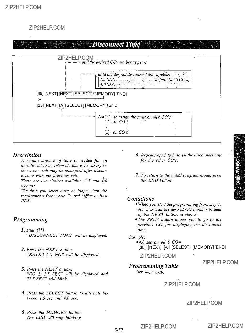
[35] [NEXT] ,Ni+XT] [SXECT] [MEkjORY][END]
;] [NEXT]
Description
A certain amount of time is needed for an outside call to be released, this is necessary so that a new call may be aitempted after discon- necting with the previous call.
There are two choices available, 1.5 and JO
seconds.
The time you select must be longer than the requirements from your Central Office or host PBX.
Programming
I.Dial (35).
???DISCONNECT TIME??? will be displayed.
2.Press the NEXT button.
???ENTER CO NO??? will be displayed.
3.Press the NEXT button.
???CO 1: 1.5 SEC??? will be displayed and ???1.5 SEC??? will blink.
4.Press the SELECT button to alternate be- tween 1.5 set and 4.0 sec.
5.Press the MEMORY button. The LCD will stop blinking.
6.Repeat steps 3 to 5, to set the disconnect time for the other CO???s.
7.To return to the initial program mode, press the END button.
Conditions
l When you start the programming from step 1, you may dial the desired CO number instead of the NEXT button at step 3.
@The PREV button allows you to go to the previous CO for displaying the disconnect time.
Example:
l 4.0 see on all 6 CO=
[35] [NEXT] [++I [SELECT] [MEMORY] [END]
Programming Table
See page

[36][NEXT][NEXT][SELECTj[MEMPRYJ[END] orfI
[36] [NEXT] [A] [SELECT] [MEMORY] [END]
Description
To detect that an outside party has hung up and then terminate the outside (after a conversation, conference etc.) a CPC signal is needed. CPC signal detection can be removed or added at customer???s request.
Programming
1.Dial (36).
???CPC DETECTION??? will be displayed.
2.Press the NEXT button.
???ENTER CO NO??? will be displayed.
6.Repeat steps 3 to 5, to program the assign- ment of the other CO???s.
7.To return to the initial program mode, press the END button.
Conditions
l When you start the programming from step 1, you may dial the desired CO number instead of the NEXT button at step 3.
~The PREV button allows you to go to the previous CO for displaying the calling party control signal selection.
3.Press the NEXT button.
???CO I: ENABLE??? will be displayed and ???ENABLE??? will blink.
4.Press the SELECT button, to alternate be- tween ENABLE and DISABLE to select the desired mode.
5.Press the MEMORY button. The LCD will stop blinking.
Programming Table
See page
until the desired mode appears .???
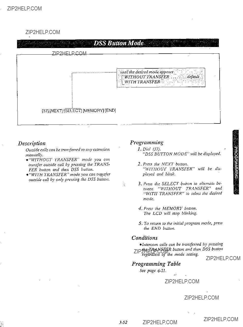
[37] [NEXT] [% ciZCT] [MEMORY] [END]
Description
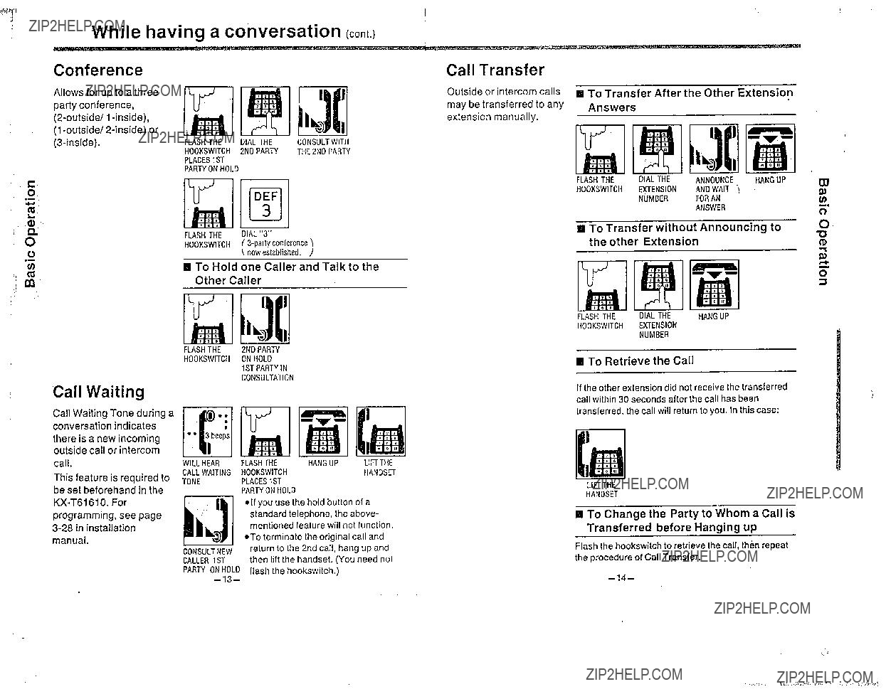
Outside calls can be transferred to any extension manually.
@???WITHOUT TRANSFER??? mode you can transfer outside call by pressing the TRANS- FER button and then DSS button. ..
l ???WITH TRANSFER??? mode you can trqsfer outside call by only pressing the DSS button.
Programming
2.Press the NEXT button.
???WITHOUT TRANSFER??? will be dis-
played and blink.
3.Press the SELECT button to alternate be- tween ???WITHOUT TRANSFER??? and ???WITH TRANSFER??? to select the desired mode.
4.Press the MEMORY button. The LCD will stop blinking.
5.To return to the initial program mode, press the END button.
Conditions
@Intercom calls can be transferred by pressing the TRANSFER button and then DSS button regardless of the mode setting.
Programming Table
See page

[39] [NEXT] [SELiECT] [MEMORY] [END]
Description
When a call is transferred to any extension, if other extension does not receive the transferred call within 30 seconds, the call will return to you.
The time may be changed to 2 minutes.
until the desired mode ajjtars
Programming
1.Dial (39).
???XFER RECALL TIME??? will be displayed.
2.Press NEXT button.
???30 SEC??? will be displayed and blink.
3.Press the SELECT button to alternate be- tween ???30 SEC??? and ???2 MIN??? to select the desired mode.
4.Press the MEMORY button. The LCD will stop blinking.
5.To return to the initial program mode, press the END button.
Programming Table
See page

[40] [NEXT] [NiXT] [SEIECT] [MEM,ORY] [END]
;] [NEXT] [AB] [SELECT] [MEMORY] [END]
Description
3 programmable feature (Fl, I??, F3) buttons
are provided with the proprietary teleph nes,
P
button can be changed from programmable feature button to call forwarding (see page
programmable feature function ???FWDIDND KEY??? mode.. .
call forwarding/do not disturblaccount code function
4.Press the SELECT button to alternate be- tween FEATURE KEY and FWDIDND KEY to select the desired mode.
5.Press the MEMORY button. The LCD will stop blinking.
6.To return to the initial program mode, press the END button.
7.Repeat steps 1 to 6, to program call forwardingldo not disturblaccount code but- ton of the other extensions.
Programming
1, Dial (40).
???M3IFWD SELECTION??? will be displayed.
2.Press the NEXT button.
???ENTER EXT NO??? will be displayed.
3.Dial the
When dialing 20, the LCD will show ???20:FEATURE KEY??? and the ???FEATURE KEY??? will blink.
Conditions
@You may repeat pressing the NEXT button until the extension number to which the
*The PREV button allows you to go to the previous extensio%??? for displaying the M3l FWD selection.
Programming Table
See page
- -

DETAILED FEATURE LIESCRIPTION AND OPERA- TION FOR EMSS
TO operate this system, after making program changes, set the System Program Switch located on the
When the unit is unused, the Liquid Crystal Display will show the month, day and rhe present time.
Description
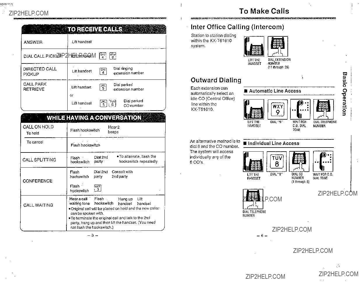
Srarrfon IO starioll dialing withill rhe
Operation
Using the handset
1.Lift fhe handset.
2.Dial the extension number (11 through 26).
3.Srarr talking
4.Hang up upon completiorz of the conversa- tion.
1.Press the
2.Dial the extension number (11 through 26).
3.Starr ralkirlg
4:Press- the
Conditions
*When a called party has the
0 The extension number of the culling party will be displayed on the LCD of the
0 The ICM indicator will be lit green while using the unit.
o The
Description
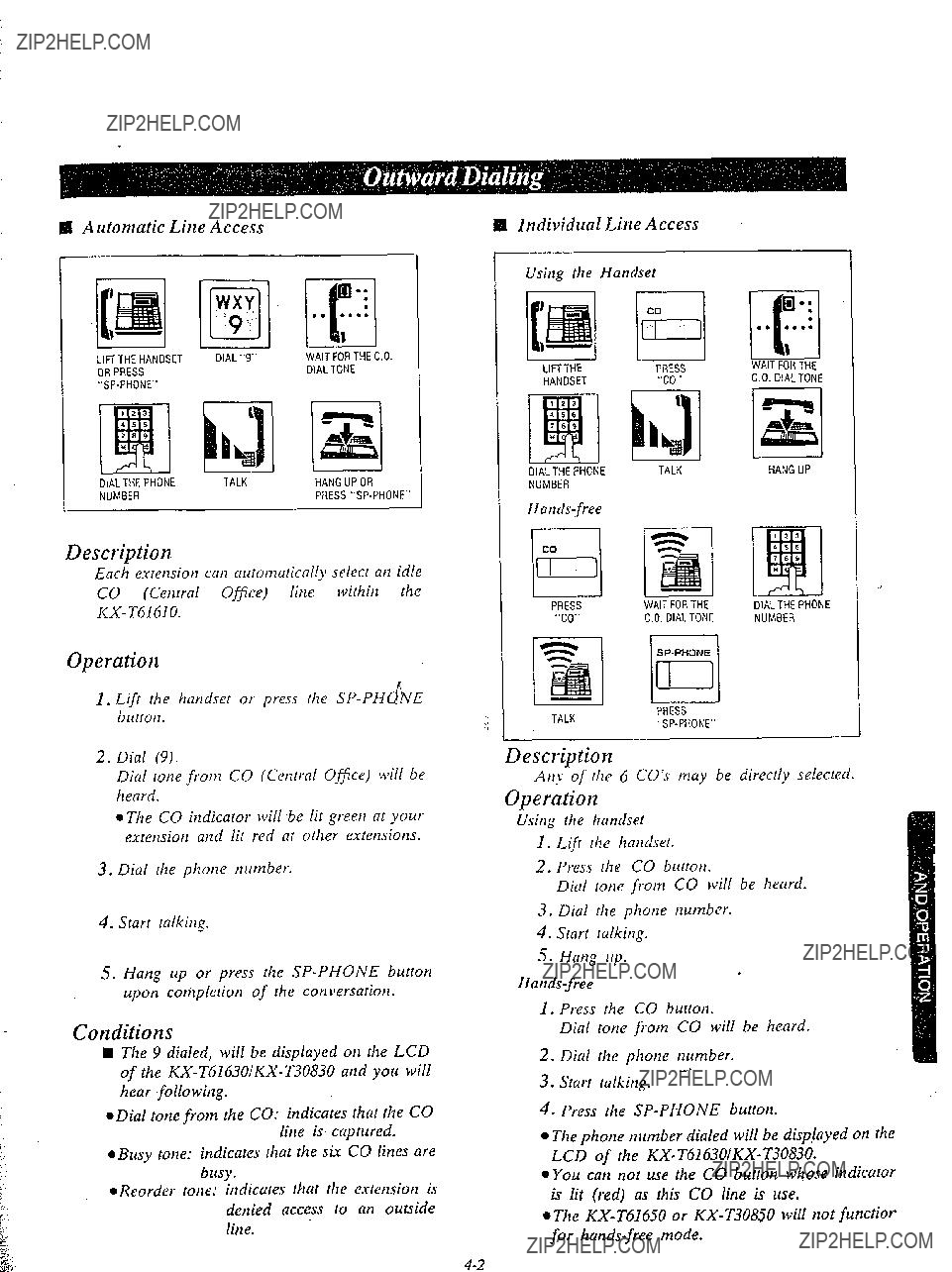
Each extension can auromatically select an idle CO (Central Office) line within the
H Individual Line Access
Using the Handset
Operation
PRESS TALK"SP-PHONE"
Description
i
l The CO indicator will
3.Dial the phone nutnber.
4.Starr talking.
5.Hang up or press the
Conditions
q The 9 dialed, will be displayed on the LCD of the
*Dial tone from the CO: indicates that the CO line is captured.
@Busy tone: indicates that the six CO lines are busy.
l Reorder tone: indicares that lhe exrettsion is denied access to an outside
AtI? of the 6 CO???s may be directly selected.
Operation
Using Ihe handset
I. Lift the handset.
2.Press rke CO buttotl.
Dial totie from CO will be heard.
3.Dial the phone nutnber.
4.Start talking.
5.Hang up.
1.Press rhe CO button.
Dial tone from CO will be heard.
2.Dial the phone number.
.You can not use rhe CO button whose indicator is lit (red) as this CO line is use.
@The

q Individual Line Access
m. pJ
Description
Any of the 6 CO lines may be selected by dial access.
Operation
1.Lift the handset or press the
???2. Dial (8) and the CO number (I through 6). Dial tone from the CO (Central Office) will be heard.
3.Dial the phone number.
4.Start ralking.
5.Hang up or press the
Conditions
0 The phone number dialed will be displayed on the LCD of the
0 Individual line access codes Dial 81 for CO I
Dial 82 for CO 2 Dial 83 for CO 3 Dial 84 for CO 4 Dial 8.5 for CO 5 Dial 86 for CO 6
El Each extension can access a new CO line withoztt hanging up.
While having B conversation,
PRESS
L
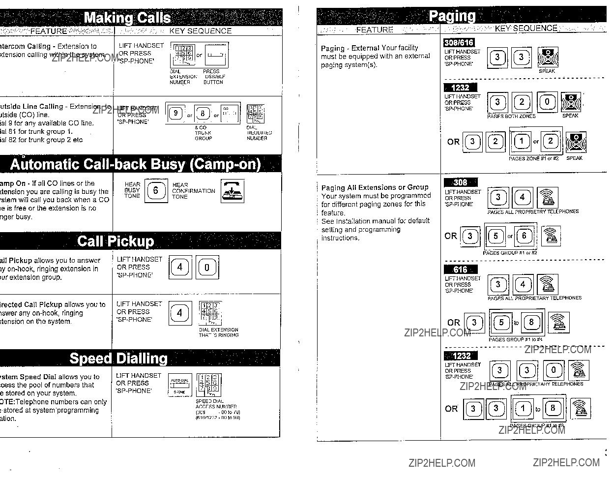
Description
There are 100 memory locations of system speed dialing available.
Operation
1.Lift the handset or press [he
2.Press the AUTO button.
3.Dial the speed access code.
sl You may press the CO butIon to select rhe CO line directly after lifting the handser or press the
Condition
*The dialed number will be displayed on the LCD of the
oContinuous use of speed dialing is possible. ex. [AUTO] (01 [O] [AUTO] [O] [ll
Chaining together two or more memory loca- tions.
l Combinations of speed dialing, one touch dialing and manual dialing is possible.
*The original conversation will be terminated and a new CO line will be accessed.
Programming
l Be sure the handset is in the cradle and the
*Set the MEMORY switch of the
@You may dial 81 through 86 instead of 9. 9 . . . . . . . . Each extension can automati-
cally select an idle CO line. 81 through 86. Each extension can select a
designated CO line.
19 or 81 through 86 must be dialed for storage. 1
W To Correct an Error while Pro~rammitq
eThe TRANSFER button is used as the CLEAR button.
After programming all the numbers, return
the MEMORY switch???to the ???SET??? position.
Dialing
ElTRANSFER
PRESS "CLEAR(TRANSFER)"
INSTEADOF "MEMORY"
bAfter pressing the CLEAR f, button, reprogram the car- I rect number.
oThe TRANSFER button is used as the CLEAR button.
1 1 1
qYou may press the CO button to select the CO line directly after lifting the handset ot
press the
II To Change a Stored Number
Repeat ???Storage??? above.
S To Conjirm a Stored Number
I
Repeat programming the same number into the same station.
When the MEMORY button is pressed, a beep will be heard.
*two beeps . ... . . . storage is correct *onebeep . . . . . . storage is incorrect
Repeat the procedure of pro- gramming.
Description
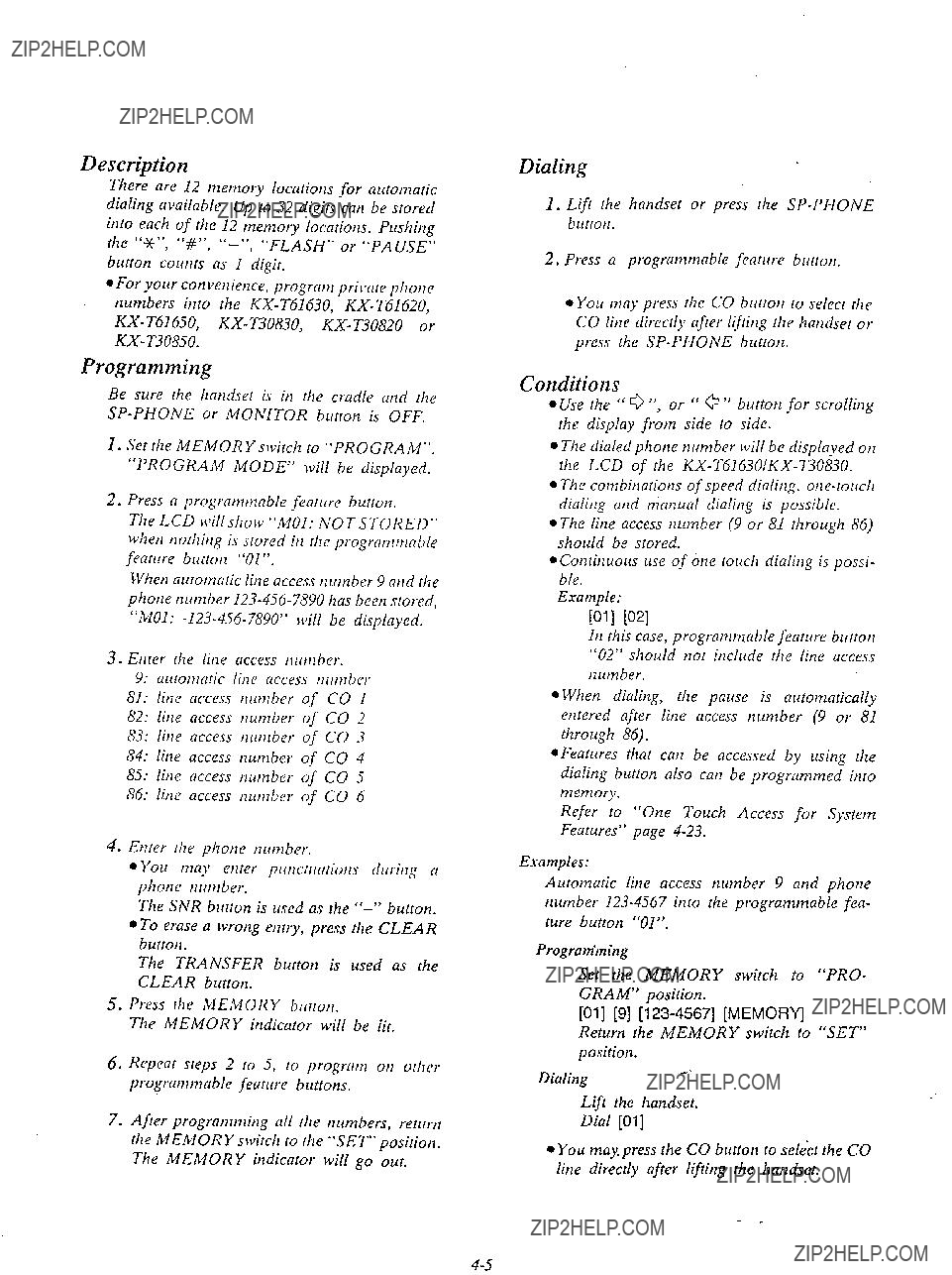
There are 12 memory locations for automatic dialing available. Up to 32 digits can be srored
into each of the 12 tnetnory locarions. Pushing [he ???*Jc???, ???#O,
button counrs as I digit.
l For your convenience, program pri\*are phone numbers into the
Programming
Be sure rhe handset is in [he cradle and rhe
1.Set the MEMORY switch to ???PROGRAM???. ???PROGRAM MODE??? will be displayed.
2.Press a programtnabie feafllre button.
The LCD will show ???MOI: IVOTSTORED??? when nothing is stored in the programmable feature button ???01???.
When automatic line access nutnber 9 and the phone number
3.Enter [he line access nunlbtr.
9:automatic line access tti~tnbcr
81:line access number of CO I
82:line access tlumber of CO 2 S3: line access nrlmber of CO 3
84:line access number of CO 4
85:line access number of CO 5
86:line access number of CO 6
4.Enter rhe phone number.
l You may etirer putic~1rrrtiotl.s drlring N phone number.
The TRANSFER button is used as the CLEAR burton.
Dialing
1.Lift rhe handset or press rhe
2.Press a programmable feature burton.
~You may press the CO burton to select the CO line direcriy after lifting rhe handset ot press the
Conditions
aUse the ??? 0 ???, or ??? a ??? button for scrolling the display from side to side.
l The dialed phone number will be
l The combinations of speed dialing.
eThe line access number (9 or 81 through 86) should be stored.
l Continuous use of tine rouch dialing is possi- ble.
Example:
Wll WI
In this case, programmable feature brrrton ???02??? should not include the line access number.
l When dialing, the pause is aulomatically entered after line access number (9 or 81 rhrough 86).
*Features that can be accessed by using the dialing button 01~0 can be programmed into memory.
Refer to ???One Touch Access for System Fearures??? page
Examples:
Automatic line access number 9 and phone nurnber
Progranitning
Set the MEMORY switch to ???PRO- GRAM??? position.
[Ol] [9]
Return the MEMORY switch to ???SET??? position.
Dialing
Lift the handset.
Dial [Ol]
lYou may. press the CO button fo select the CO line directly after lifting the handset.

Calling doorphone 1
I Calling
Description
Up to two doorphones
Operation
Dialiq fo rhe doorphoties
1.Lifr rhe handser or press rhe
2.Dial 131) for calling doorphoile 1. Dial (32) for calling doorphone 2..
???DOOR I??? or ???DOOR 2??? will be displayed.
3.Wait for the confirmation tone and then start talking.
4.Haq up or press rhe
Conditions
l The features, for imtance, hold, tramfer and so otl, cati not be activated by the doorphone.
Description
A disbrzcbve dial tone will be heard from he hnrldset if rhe esrmsion user has prel~iously acfivared a special fearure.
Operation
None
Conditions
There are two types of dial tones.
Dial lolIe I: ordirlary dial tone
I
III
Dial Iolle 2: ,c,hcn any of the following fea- tlo???es is activared:
Do tlot Disturb.
Dial Call PickLrp Deny
Call Forwarding.
Dam Line Security.
Background Music
I I I I I
WBR
I I
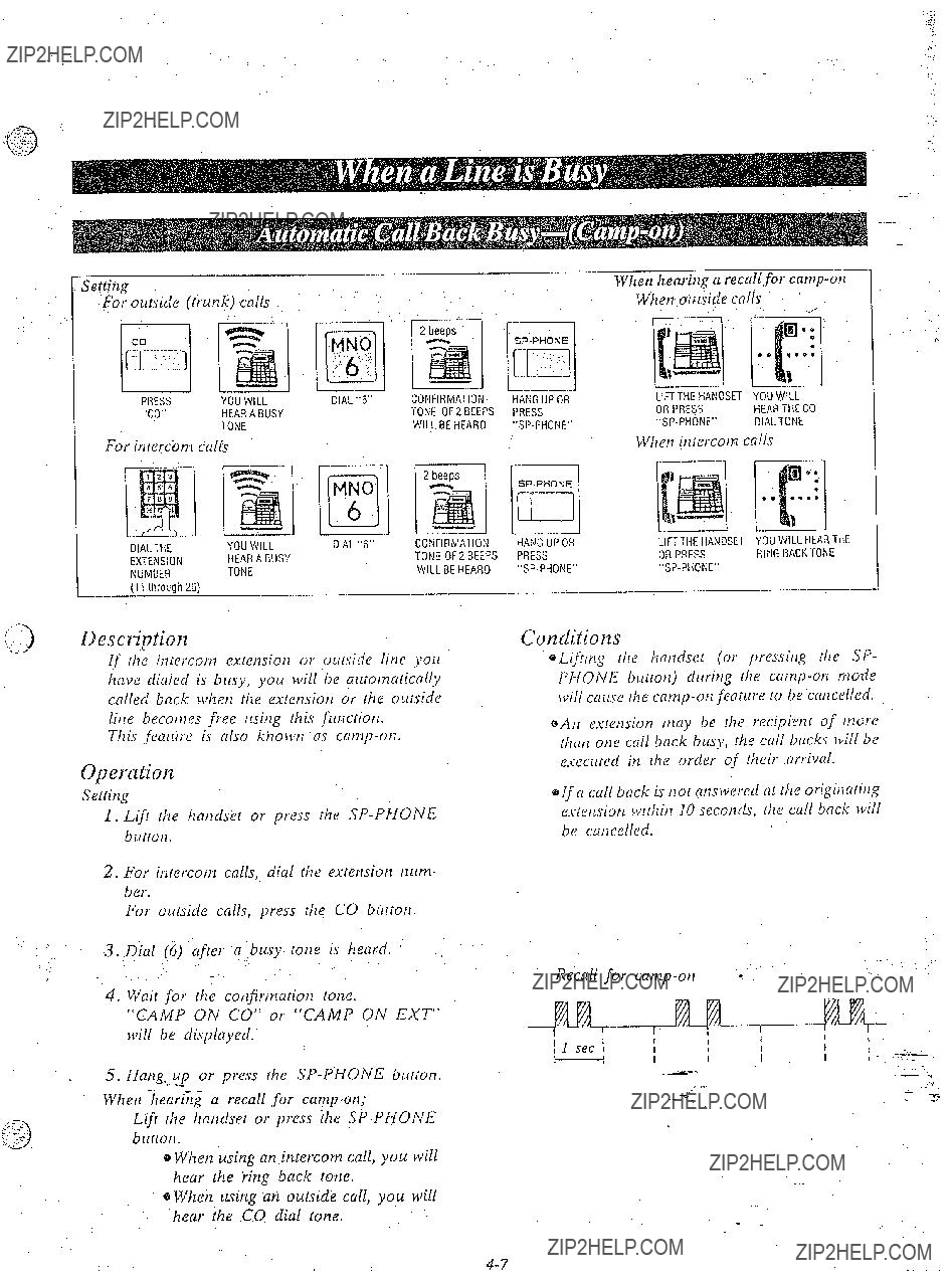
-
For inierc&n calls
If rile itlrercotn extensiotr or olrtside line you hnve dic~leclis busy, y0l.i will be uutotnaricnlly called buck whet! the estensiotl or the outside line beconIes free llsitlg this futicriotl.
This feuiire is ciiso kilorvti ns
Qpemtion
Setting
1.Lift rhe hntidset or press the
2.For intercom calls, dial tlie extensiotl tzrrtn- ber.
For olttside cnlls, press the CO button.
3..Dial .(6) crfier a busy tone is heard.
4.Wait for the cotIJirt7iatioti tone.
???CAMP ON CO??? or ???CAMP ON EXT??? will be displayed.
5.
Whet1 %eariYly a recall for
Lift rhe liatldset or press the
e When using an intercom call, you will hear the iing back totle.
er?Yhen using an outside call, you will hear the CQ dial tone.
WL???n honr.irin n r0rc1lLfor
.,I..
Conditions
e Liftitlg the hculdset (or pressitlg tile SP- PHONE button) dltritlg the
eAtr estetlsiom muy be the recipient of more thrltl one cdl back busy, the call backs will be executed in the order of their nrrivd.
@If o call buck is not rcns\vered nt the originatitlg es;etlsion tvithitl IO secotzcls, the call buck will be catlcelled.
Recall for

Descriptior2
If rhe estemiot7 you hnvi: dialed is busy. yorr calf irlfortn that exretrsion [hat morher itrtercottl cali is waiting by three beeps.
LIFiTHEHANDSETPRESS
ORPRESS"LNR"
Description
The last photle tlilttiber dialed 011 atz outgoing call (CO line) cat1 be redialetl.
For use of [his feature, the other extension is requited to be set for this feature beforehand in
Opercrtion
\
the
Operation
1.Lifr the hcitlclset or pwss the
2.Dial the extension nutnber.
3.When you will hear a busy lotze, dial (1) and wait for m mswer.
Conditions
0 To answer your signal, see ???Call Waiting??? 011 page
*If the other party is usitq data equipment, you may not be able to use this feature.
???If b busy lone is heard ufter dialing 1, it indicates that &e other party has not beet1 ser with this feature.
2.Lift [he hadset or press the
2.Press the LJJR buttotl.
eYou may press the CO brltrotz to select the CO line directly lifter lifting the hatdset or press.
:: the
.
Conditions
*Up to 32 digits ccttl be siorcd utzcl redialed.
iz+Whet2 cullitlg or while itz the cotlversalion ttlotle, pressitlg [he LNR buttotz will cause the medial to operfice after about 3 secotids.

L.I
OperatiolYz
,.,Lift rhe hnttdser or press llze
@?Vhen he ??????Autotnntic At7swering Selecrion??? fetrhrre has been selected lo the L???mcirluc~l??? mode in the
* Wlzetl receiving cite itzlercom cdl, yore mny press rhe ICM button whose indicator is fhhing quickly nnrl talk.
@When receiving nn outside call, you may press the CO button whose indicator is f&a&zing red quickly and talk.
???If nny incoming calls from the Central Office ore received nt Ihe snme time except preferred C.0 line, you must lift the handset and then press the ???CO butlon whose indicator is flushing (red color) quickly.
Co,nditions
???If CLcnll reaches tfzrough the CO line to which the CO&e number is not assigned, the ICM indicntor wiil flash quickly. And the CO call cnn be received by pressing the ICM or ,the
Description
Allows extension user I0 cmswer 1117ititercom call in the au~omnlic
1.For settitrg, press the AUTO AN.7 butt&n. The AUTO ANS indicator will be lit.
2.Fbr ctrncelitrGotl, pres.r tile A UT0 ANS bllrton ngnin.
The AUTO A NS indicetor will go oL[t.
Description
QThe
.

Description
An exrension user cm mswer ally ritlgrtlg esiension within their O~II pickup group.
Operation
1.Lift rhe hflndsel or press Ihe
2.Did (40) cd wait for the confirmation tone.
3. Start talking.
is???Lb
QDial Call Pickrip will work for incortlillg cnlls (intercom, ourside and doorphone) bllr \vi/l not w0rk for
@If a ringing exterzsion is oulsicle the pickup group or is in rhe dial call pickup denied iTlOde, then 0 reorder tone will be heard, through the use of this feature.
6,ReIer to ???Dial Call Pickup Group Assigtrmetrr on page
SDirrl Call Pickup cm use with the present call placec! on hold.
Descriptio 11
An estemioti ,tln), atmver (111itlconliq call flm~ is ringitlg at mother e.vtcs/rsiotl regardless of the picklrp group.
Operation
1. Lifi the hntldsct or pwss the SPyP/lIOtVE :
J
brrrtot1.
2.Dial (4) c7rrrlhen rile fstclrsioti Il[t&er (I [ dlroligh 26) (it wliicll 1~11 is
3.Wait for cotlfirttici~io~l totle aud then stnrt talking.
Conditions
To retrieve a parked call at any extension
2:.
Description
Allo~vs any estensiotz user to retrieve a call (intercom or outside) on hold at any extetuiotz.
Operation
Whet1 atI intercom or outside call is otz hold.
1.Lift rite handset or press the
Exatnple:
Mark is ralkitzg???with extensiotz 15 0t1 his desk, and theta moves to atlother rootn placing the call on hold.
He resumes the conversatiotl using anolher estensioti.
Pressthe HOLD biiliotr.
kmg r1p Nllci tl1en go
2.Dial (5) atld rhe esretuiotl number of the phone oti which rhe cnll is placed 011 hold. (Connecrion is tlow tnade with the party who lvas on holcl.)
3.Wait for the cot+w7c~tion tot!e and then start talking.
Even when several outside calls areplaced on hold sitnultaneously, you can retrieve the desired outside call from another extension as following.
I. Dial (53).
2. Dial the CO aumber. (1 through 6).
Conditions
@Call park retrieving is possible regardless of the handset position of the phone which has
placed t!je call on hold.
@If rhe exretlsiotl thar JJOL~ want to retrieve the call park has several calls on hold, ottly the last call ot1 hold will be retrieved.
and the
exremiotl-.

To answer c1 doorphone
Operation
L.ift lhe hmdset or press rhe
Conditions
*If culls from cloorphotzes clre tlot nrmverecl lvithitz I5 secotlds, the ccllls dl be ccmcellcd.
@Ring
fi
Ccich exretisiotl lrcts IO be progmmtned fot recei\+ng from doorphoties. See ???Programtn- nble Doorphotle??? otz pctge
A differetlr ritlgitig pnttern is rmd to distitiglrish . intercom cdls from itzcotnitlg outside cdls.
Operation
Notie
Conditions
A~itonlotic ritlg back for the canlp on feature will ritlg dijreretltly from the ritlgitlg OH ititer- coin, outside, md doorphot~e cczl1.r.
Incottling outside calls (itzcluding ourside hold recall)
Itlrercotn crtlls (itlcl~rcliq itzlercotn hold recall)
Doorphotle calls

PRESS"C0"
. . .
uescrlptlon
,P .I r
1J you wispy to leave yottr phone rtnattet7ded bril
wanf the caller you are itr conversalion with to wait, call hold may be used. Outside or inter- com calls may be placed on hold.
;.Calls on hold can be released by other exten- sions.
Operation
1.Y011 are in conversation with at1 outside or internal party.
2.Press the HOLD burrott.
The indicator of CO or ICM button lvhich is on hold will flash slowly (green color). The confirmarion tone of 2 beeps will be J1eai.d.
To Retrieve af tJle holding extension,
press the CO or ICM button @lashing green). The indicator light will return to a steady
green.
To Retrieve fro,, artorller extension,
press
or
dial (5) and then the extension (11 through 26) or CO (81 through 86) number of the phone on which the call. was place2 on hbld. - -
PI LABI
yB=RI tlzrough 86 (CO)
a,The green flashing indicator aI the ???held extension will mm to red.
eRefer to ???Call Park Retrieve??? on page
OlAL"5"DIALTHE HOLOING
Conditiorzs
*An Intercorn hold can be activated on one extension only.
@An Outside call hold can be activated on six CO???S.
.If???a call is on hold for more that7 30 mitiutes, a
hold t& retninder will be sounded and the call will be terminated automatically.
A hold time reminder is sounded #trough the
~Calls on hold will be recalled ei(her after 30 seconds, 1 minule, I rtiinufe and 30 seconds or 2 rtlitlutes, once handset is replaced (or the
If hold recall time is sef to ???DISABLE???, if wiil not be recalled.
Refer to ???Hold Recall Time Ser??? on page
0 The hold rime reminder is activated, even if rhe hold recall rime ser is proiratntned to ???DIS- ABLE???.
@When lifting the handset (or press the SP- PHONE button) :
before recal1ing.d. dial tone will be heard with the call on hold.
while recalling... Only the first call. on hold will be released and etltered into rhe cotiversnlion mode.
:t i ???8
i,
???!
.i
i
-
-
1
Description
An intercom or outside call placed on exclusive hold can not be released by any extension other than the phofle which has placed the call on hold.
.:.
2. Press the HOLD buttor!.
The indicator of CO or ICM bllttorz which is on hold will flash slowly (greeti color).
A confirmation torte of 2 beeps will be heard.
3.Press the HOLD button, again.
?;he indicator will flash in groups of 2 (green color).
4.To retrieve, press the ICM button or the CO button whose indicator is flashing in groups of 2 (green coLor).
The indicator on the ICM or CO button will return to a steady green.
Conditions
@An Intercom hold can be activated on one extension only.
@Air Outside call hold can be activated on six
CO???S..J
@Ifa call is on hold jor more thall 30 minutes, a hold tinle reminder will be sounded, and the call will be terminated automatically.
A hold time reminder is sounded through the
.:.; eCa1l.r otz hold will be recalled either after
0 The hold time reminder is activated, even if the hold recall time set is??? programmed to ???DIS- ABLE???.
*When lifting the handset (or . press the SP- PHONE button) :
before recalliq....A dial tone will be heard with the call on hold.
You mny dial another phone number.
while recalling.. . OPlqiihe first call .on hold wilM$????released and entered into the conversation mode.

DescriptiOn
Allolvs fo; rip to a three party conference,
Opeiyation
1.Press the CONF button, to place the first
. party on hold.
2.Dial the number of the second party.
If second party does not answer, press the CO button of the outside party concerned, or the ICM button to return to the first party.
3.Press the CONF button.
A conJirmation tone will be heard.
3 pflrty confesence is now established. ???CONF??? will be displayed.
@You may press the HOLD button instead of the first CONF button.
-
To terminate conference
Replace the handset or press the
eThe other two parties will be directly con-
To ten&ate one caller and talk to the other caller. elf bdth the confereflce parties are on the
outside:
Press the CO buttotl to talk to the desired party.
elf both the conference parties are on the extension:
Press the ICM button.
You will be connected to the first participant.
???If the conference parties are 0); the outside and extension:
To talk to the outside party, press the CO button.
To talk to the extension partyS press the ICM button.
To leave the other two parties on hold at the same time.
Press the HOLD button.
eon case the other two parties are 011 the extension, the other two parties can not be left on hold.
~Pressirrg the ICM brlttotl :/???)r corl,ferellce, a(/o~.s yore to exit from the co~lferCIl(.C (lrlti to access an intercom. - L
n 1c
To terminate the original call and talk to the new caller.
-
To place the original call on hold and talk to the new caller. elf both original call and new call are intercom calls:
(The ICM indicator will change lighting intoflashing quickly when new call reaches.)
*If original call is CO call, and new call is CO call or intercom call: or
If original call is intercom call and new call is CO ca???ll:
Description
This feature is required to be set beforehand in the
For programming, see page
Operation
3.Consult with the new caller.
4.Press the ICM button to terminate the second call and to return to the original call.
@Iforiginal call is CO call, and new call is CO call ???or intercom call:
or
If original call is intercom call and new call is co call:
1.You will hear. a call waiting tone.
2.Press the HOLD button for placing a ???conversation on hold. .
3.Press the CO or ICM button whose indicator is f7ashing quickly.
4.Consult with the new caller.
5.Press the CO or ICM button whose indicator is flashing
To Retrieve the Call
if the other extension did not receive the transferred call within 30 seconds after the call has been transferred, the call will return to ~0~1.In this case:
LIFTTHE HANDSET
OR PRESS
Description
Outside or intercom &lIs may be transferred to any extension manually.
Operation
1.YOLL are engagecl in a call (outside or intercom).
2.Press the TRANSFER button.
3.Dial number of extension (11 through 26) to which the call is transferred.
4.For, Unscreened call transfer, replace the handset or press the
For Screened call transfer, wait for neb3 party to answer and announce call, then replace the handset or press the
To retrieve the Call
If the,.o.tJer extension did not receive- the
Press the CO or ICM button whose indicator is flashing slowly or lift the handset.
TO change the party to whotn a call is transferred before hanging up
Press the CO or ICM button whose indicator is flashing slowly to retrieve the call, then repeat the procedure of Call Transfer.
Conditions
8 Upon recall to the transferring exlension, if call is not answered in 30 minutes it ,will be
A
HOLD
,,
Descriution
Allotvs an extension user to alternate between a
CO party and an Intercom party.
;:,
Operation
1.Press the HOLD button to place the first party on hold.
2.Dial the second party.
3.Consult with the second party.
4.Press the HOLD button to place the second pariy on hold.
5.Press the CO dr ICM button whose indica- tor is flashing slowly.
6.Consult with the first party.
7???.
8.Press the ICM or CO button whose indica- tor is flashing slowly.
9.Consult with the second party.
::10. Repeat step 4 to 9.
Conditions
eTo release the call splitting mode, press the CO or ICM button without pressing the HOLD button.
Conversation will be terminated and call OH hold will be returned to conversation.
.
A 70

. . : Description
Allows an extension user to alternate between two intercom parties.
Operation
To access
LIFTTHEHANDSETDIAL dRPRESS
PAGEWAITFORAN
ANSWER
ANOTALK
El Page will be heard only from the
KX- T61620, KX- T61650, KX- T30830,
CONFIRMATION
TONEOFI BEEP
WILLBEHEARO
1.Press the HOLD button to pince the fir.rt party on hold.
2.Dial the second party,
3.Consrtlt with the second pnrty.
4..Press the HOLD button to place the second party on hold.
5.Consult with the first party.
6.Press the HOLD button to place the first party on hold.
7. Repeat step 3 to 6.
Conditions
~To release the call spIittjng???mocle, press the ICM button instead of the HOLD button. Conversation will be terminnted and call on hold will be returned to conversation.
Description
Allows paging to ail extensions.
Operation
To accesspaging;
I.Lift the handset or press the
2.Dial (34) ~117~1 tvait for confirmation tone (one beep).
3.Start pnging.
4.Wait for an answer and talk.
aWhen an e,&nsion is in use, that extension z cannot gain access to paging.
0 When any extension is using the paging (a!1 extensions, group or external), you camot
access to paging.
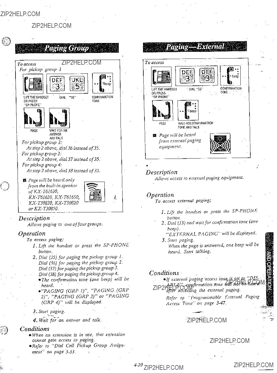
0 access
ror pickup group 1
PAGE WAITFORAN
ANSWER
ANDTALK
For pickup group 2:
At step 2 above, .d,ial36 instead of 35.
For pickup group 3:
At step 2 above, dial 37 instead of 3.5.
For pickup group 4:
A f step 2 above, dial 35 instead of 35.
@ Page will be heard onl}) from the
Description
Allows paging to one of four groups.
Operution
To access paging;
1.Lift the handset or press the
2.Dial (35) for paging the pickup group 1. Dial (36) for paging rhe pickup group 2. Dial (37) for paging the pickup group 3.
Dial (38) for paging the pickup group 4. OThe confirmation tone (one beep) will be
heard. -
e???PAGING (GRP l)???, ???PAGING (GRP 4???, ???PAGiNG (GRP 3)??? or ???PAGING (GRP 4)??? will be displayed.
3.Starr paging.
4.Wait
Conditions
*When an extension is in use, that ex:tension cannot gain access lo paging.
*Refer to ???Dial Call Pickup Group Assign- ment??? on page
???0 access
PAGE WAITFORCONFIRMATION
TONEANDTALK
f&i kage will be heard from exrernal paging equipmerft.
Description
Allows access to external paging equipmenr.
Operation
To access external paging;
1.Lift rhe handset or press the
2.Dial (33) and wail for confirmation tone (one
beep}.
???EXTERNAL PAGING??? will be displayed. 3. Start paging.
When the page is answered, one beep will be heard. Start talking.
Conditions
;If external paging access tone is set to ???DIS- ABLE???, confirmation tone will not be heard after accesshg the external paging.
Refer to ???Programmable Exrernal Paging Access Torte??? on page

To transfer a call to the paged person
4; Start paging.
5.Wait for an answer.
6.Hang up or press the
?o answer
TALK
Description
A page from the
Operation
To answer paging;
1.Lift rhe handset or press the
2.Dial (43) and wait for confirmation tone (one beep).
3.Start talking.
Conditions
aIf a call and CO number has been.paged and transferred, you may answer by pressing Gie CO button whose number has been paged and indicator is flashing slowly (red color), instead of dialing 43.
. . . ..-
._???
- -
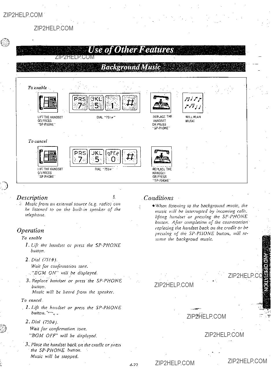
To enable
To cancel
Description
.i Mu& from at7 extertlal source (e.g. radio) .catl be listetled to on the
Operation
To enable
1.Lift the hatldset or press the
2.Dial (751#).
Wait for cotifirmalion totie.
???BGM ON??? will be displayed.
3.R&Aace???hcuzdset or press the
Music will be heard from the speaker.
To cancel
1.Lift the handset or press the
2.Dial (750#).
Wait for confirmation lone.
???BGM OFF??? will be displayed.
3.Place rhe hatldset back ot1 the cradle or press the
Music will be stopped.
3EPLACE THE iANDSET
ORPRESS
Conditions
8 Whet1 listening to the backgroutzd music, the
???music
.

To enable
Be sure the
PRESS ???MUTE???
@The. MUTE indicator will flash.
To cancel
PRESS
AGAIN
Description
Use when you do not want your voice to be heard by the other party.
Operation
To enable
Be sure the
oThe MUTE indicator will flash.
To cancel
Press the MUTE button again. *The MUTE indicator will go out.
Conditions ,.
l This $eatur& can be activated in speakerphone mode
To Program
Set the MEMORY switch of the
Example:
Paging All Extensions (Dial 34).
After programming 6Ill! the system .fea- lures, return the MEMORY switch tc ???SET???.
To Access
Description
Features that can be accessed by using the dialing button also can be programmed into memory.
(e.g. Paging All
Operation
1.Lift the handset or press the
2.Press the PROGRAMMABLE FEA- TURE button.
Call
If the calling party on hold hangs up, the tine is terminated.
Description
Allows estension user to access feafures of the central o.fice or host ???PBX. (example: call lcaiting feature can be supplied by central office. )
..
I. While haviilg a con~~erscirion, another party ccills and a call waiting lone is heard.
2.Press the FLASH burton.
8 T1zeorigitlal call is placed on hold and the
nelv call can be answered.
3.Press the FLASH button agaiti.
0 The original caller can ?bespoken to again and the new call is placed on hold.
@If the calling party oii hold hangs up, the li!le is rertninated.
Conditions .
8)The external fea:ure (call waiting) can only be *??? accessed when engaged on an aulside call.
The
*???Flash??? can be stored into tnemory in the . same way as ???Storage??? on page
~YOLLmay access some features of host PBX using the Flash button. If
.

Forced Mode
I$ Making a Call
: .:,
???l Receiving a Call
If you want to record a calling party???s account code in the SMDR, follow the
Within 30 seconds offinishing your conversation or while having a conversation,
FWOlONO
a???
ODialing the account code must be done before hanging up,
option Mode
111Making or Receiving a Call
If you want to record a calling or called party???s account code in the SMDR, follow the
Within 30 seconds offinishing your conversation or while having a conversation,
0 Dialing the account code must be done before hanging UP.

Description
This ~yeature gives each message of the SMDR an account code of the called or calling party.
Station Message Detail Recording (SMDR) is cbst saving feature that records all incom-
t ing and outgoing calls through the CO line, 1
This feature has two modes ???Forced??? and ???Option???.
In the ???Force>??? mode, the account code must be entered every time the extension user dials. In the ???Option??? mode, the account code may be entered when a record of the account code is needed.
When setting to the ???Forced??? mode, see page
The???programmable feature (F3 only) button of the
For programming, see page
Operation
Forced Mode
sl Making u Call
1.Lift the handset or press the
2.Press the CO button.
The FWDIDND Indicator will flash.
3.Press the FWDIDND (or F3) button,
???ENTER ACCNT CODE??? will be dis- played. The FWDIDND Indicator will light. Intermittent tone is heard.
4.Dial the account code.
Account code must be 4 digits. CO dial tone_ will be heard.
5.Dial the phone number.
~You may dial ???9 or 81 through 86 instead of pressing the CO button.
- -
1.Press the FWDIDND (or F3) .button. ???ENTER Ai=CNT CODE??? will be dis-
played. The FWDIDND Indicator will light.
2.Dial the account code.
Account code must be 4 digits.
@Dialing the account code must be done before hanging 1 up,
Option Mode
$IBIMaking or Receiving a Call
If you want to record a calling or,called party???s ???. account code in the SMDR, follow the below- mentioned procedure.
Within 30 seconds of finishing your conversa- tion or while having a conversation,
1. Press the FWDIDND (or F3) button. ???ENTER ACCNT CODE??? will be dis- played. The FWDIDND Indicator will light.
2.Dial the account code.
Account code must be 4 digits.
eDialing the account code must be done before hanging ~tp.
Conditions
*Account code must be required 4 numerical digits except for the q and q buttons.
???If you enter the wrong account code, press the FWDIDND button and enter the correct code.
q If account codes are programmed with tele- phone numbers for one touch dialing or system speed dial&= you need not to dial an account code
.
- L

Inter Office Calling (Intercom)
Programming
*Be sure the handset is in the cradle and the
leaStorage
,. ???f y. ???@ To Correct an Error while Programming
(CONSOLE)PAIR . PAIR
TELEPHONE TELEPHONE
TRANSFER
PAIR
TELEPHONEPRESS "CLEAR(TRANSFER)"
INSTEADOF "MEMORY"
OAfter pressing the CLEAR button, reprogram the cor- rect number.
oThe TRANSFER .button is used as the CLEAR. button.
*You may dial 81 through 86 instead of 9.
9 . . . . . . . . . . . . Each extension can automati- cally select an idle CO line.
81 through 86 . . Each extension can select a CO line designated.
9 or 81 through 86 must be dialed for storage.
H To Change a Stored Number
Repeat ???Storage??? left side.
Is To Erase after Progranming
*The TRANSFER button is used as the CLEAR
*
button.
Example:
Paging All Extensions (Dial 34).

Description
El DSS (Direct Station Select) Button:
mukes. the dialing to the extensions very easy. You can reach the extension party by simply pushing the DSS Button.
q Programmable Feature Button:
lets you access various features of
Operation
Inter office Calling (Intercom)
1.Lift the handset or press the
2.Rress the DSS button of Console.
3.Start talking.
4.Hang up or press the
Programming
*Be sure the handset is in the cradle and the
aSet the MEMORY switch of a pair telephone
One Touch Dialing
1.Press 7.1programmable feature button of Console.
P
iOne Touch Access for System Features
Example:
Paging All Extensions (Dial 34)
1.Press a programmable feature button of Console.
2.Dial (34),
3.Press the MEMORY button of pair tele- phone.
Dialing
1. .Lift the handset or press the
button of pair
2.Press the programmable feature??? button of Console.
Conditions.
Refer to ???One Touch Dialing??? page

(Extension 11 only)
DIAL THE
PHONE
NUMBER
Description.
When rhe dialing mode is required to change a pulse mode to a tone mode in one dialing sequence, this feature is used.
(e.g.
Operation
: ,; ; ???i.
1.Dial the phone number. (prrlse Inode) .. :.i: :.:
2.Dial (++ #).
3.Dial the phone number. (tone nlode)
Conditions
e When you dial using this feature, you must use Ihe line set to a pulse mode.
Phone number after dialing ???X #??? will change ???to tone mode.
Example:
lorlg dislance service company
Long distance no.
OPulse mode is required by local access tele- phone number of rlze alternate long disrance service company.
Uervice of MCI, SPRINT, METRO or other sysremk is used.
1: for PM
Description
When the present time is out of order, yowl cm adjust by following procedure.
Operation
I.Lifr rhe handser or press the
2.Dial (77).
3.Enter rhe hour with 2 digits. (01 rhrough 12)
5.Dial (0) for AM or (1) for PM:
6.Press the # burron.
Conditions
l Instantly after pressing the # button, new time
counting lvi$tart.
Eve
*Time setting is .,,done through extension II-
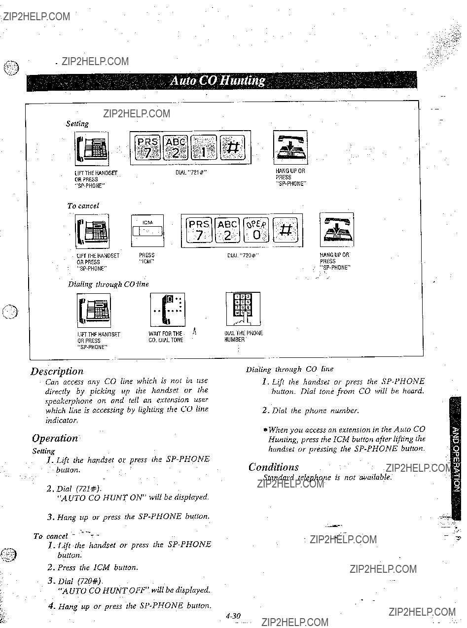
Setting
-
To cancel
.. :.
dialing through CO line
J
Description
Can access any CO line which is not in use directly by picking up the handset or the speakerphone on and tell an extension user which line is accessing by lighting the CO line indicator.
Operation
Setting
1.Lift the handset or press the
2.Dial (721#).
???AUTO CO HUNT ON??? will be displayed.
3.Hang up or press the
To cancel -
1.Lift the handset or press the
2.Press the ICM button.
3.Dial (720#).
???AUTO CO HUNT OFF? will be displayed.
4.Hang up or press the
Dialing through CO line
1.Lift the handset or press the
2.Dial the phone number.
0 When you access an extension in the Auto CO Hunting, press the ICM button after lifting the handset or pressing the
Conditions
Standard telephone is not available.

@Besure the handset is in the cradle and the
l Set the MEMORYswitch of the
"PROG&iiw.
Setting
88 After programming all CO buttons, return the MEMORYswitch to ???SET???.
??? Description
Allows each CO button to change into CO number which is different from printed CO number.
Operation
e,Be sure the handset is in the cradle and the
o$et the MEMORY switch of the
1.Press CO button which is changed into different CO number.
2.Dial the CO number which is set newly (1 through 6).
3; Press the MEMORY button.
@After
Setting
???4After programming all DSS buttons, return the MEMORY switch to ???SET???.
Description
Allows each DSS button to change into exten- sion number which is different from .printed extension number.
Operation
OBe sure the handset is in the cradle and the
eSet the MEMORY switch of the
1.Press DSS button which is changed into different.
2.Dial the extension number which is set newly (11 through 26).
3.Press the MEMORY button.
???After programming *all DSS buttons, return the MEMORY switch to ???SET???.

Switching to tone alerting
Description
???Voice alerting??? (thibugh
This feature is required to be set beforehand in the
1.Lift the handset or press the
2.Dial the extension tiumber.
3.Wait for a confirmation tone after inter office calling.
4.Press the ++ button.
The ring back tone will be heard.
Tone Ringer on the called party???s extension will be ready- to be activated.
Description
Lamp indicators corresponding to the status of the CO (Central Office) and the ICM (Inter- com) buttons.
Explanation
l ICM indicator light
bin usefor intercom *in usefor CO line ono which the CO line
number is not assigned.
.-
J
Description
In the event of a power failure each CO will be connected to assigned, extension.
CO ,I is assigned to extension 1J. CO 2 is assigned to extension 12. CO 3 is assigned to extension 13. CO. 4 is assigned to extension 14. CO 5 is assigned to extension 15. CO 6 is assigned to extension 16.
Operation
*if extension 11 through 16 is connected with
.switch on the
Description
The elapsed time (from dialing to replacing- the handset) on originating an outside call will be displayed.
Operation
None
Conditions
l When intercom calls, the duration time of conversation is not displayed.
aRefer to ???Duration Time Count Start Mode??? on page
Conditions
aDuririg power outage, all features are lost except for incoming and outgoing CO calls from extensions 11 through 16.
*If extension 11 through 16 is connected with a KX- T61620, KX- T61650, KX- T30820 or
*There is no memory loss except for the camp- on, saved number redial and the last number redial during power failure, memory is pro- tected by 21 day rechargeable battery.
Rechargeable battery is good for 5 years.
OThe Backup Adaptor
Description
If a handset remains off hook or is disconnected at the other end, a reorder tone will be heard. When ???Calling Party Control (CPC) Signal??? mode is set to ???DISABLE???, the reorder tone will not be heard. (see page
Operation
None
Conditions
0 The party whose handset remains
.
Description
Any telephone instrument, whether (KX- T61630;
Operation
Setting
To cuncel
Operation
1.Lift the 17m7dset or press the
2.Dial (731#).
\t???oit for (7 cot7firn7ntiot7 toi7e. ???C.PICKUP
DENY??? will be displayed.
3. Hang up or press the
To cancel,
1.Lift the handset or press the
2.Dial (730#).
Wait for a confirmation tqne. ???C.PICKUP
ALLOW??? will be displayed.
3. Hang up or press the
Coditions
While yollr estetzsior7 is in the ???Dial Cull Pickup
Derly??? mode, you can place or receive olctside
or intercom calls.
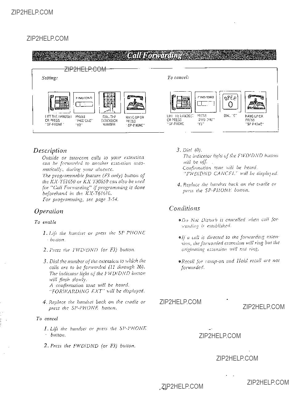
Setting:
FWQ/DNU
El
Description
Outside or irttercom calls to your extension curl be fotxiwrded to at7other c.vtetrsiot7 a1t(o-
tnnricnlly, drlritig yoltr ctbset7cf.
The progratwmble feature (F3 ot7ly) button of the
For prograrm7it7g, see page
Operation
To enable
1.Lift tile I7at7d.yet or press the
2.Press tl7e F\t???DiDND (or F3) button.
3.Dial the tzunzber of the extensiotl to which lhe calls are to be forwarded (11 through 26). Tl7e it7dicator lighr of the nVDIDh???D blrrrot7 Ivill flash slowly.
A cotzfirtnation totze will be heard.
???FOR \VA RDING EXT??? will be displayed.
4.Replace rfze hat7dser back 017 rl7e cradle ot press the
To cancel
1.Lift tl7e hat7dset or press the
2.Press (he FWDIDND (or F3) button.
To cancel:
3. Dial (0).
The itltiicntor ligl7t of (he FIYDlDh???D blr(rot~ rL,ill be Off.
Cot7firtt7aiion tot7e \c,ill be Ilearti.
???FWDIDND CANCEL??? \\,ill he tlisI~lrr~~ed.
4.Replace rile l7at7drc~ back 017 rile cradle ot prfs.s tile SP- PHONE blittotl.
Conditions
0 Do Nor Distllrb is cat7celled Jvhetl call for- lt.ardittg is established.
0 If a call is directed to tl7e forwardit7g estet7- sioll, the forwarded extension will ring Our the origit7ari,ig e.vlensiot7 ivill l7ot rit7g.
@Recall for
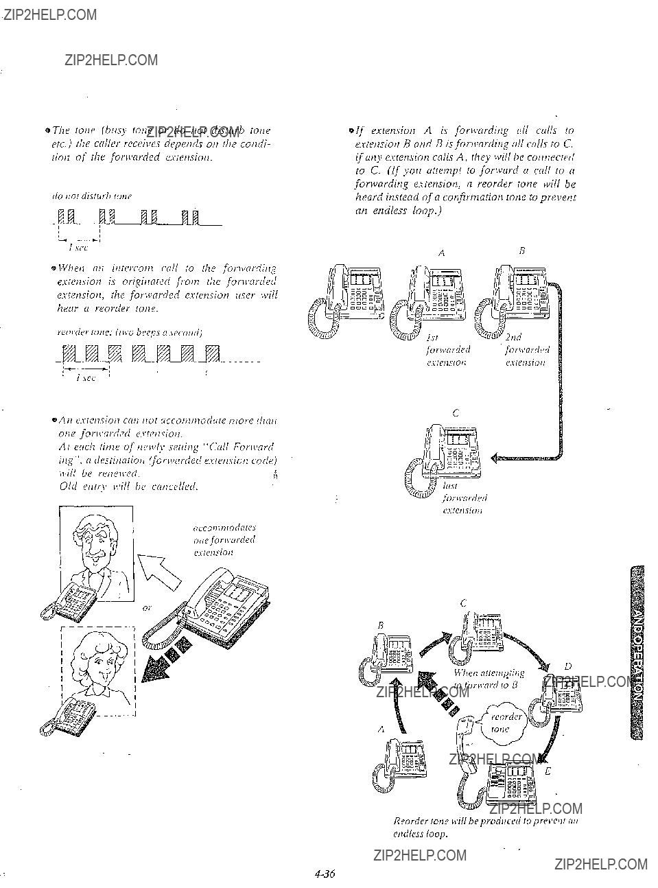
oT17e tot7e (bllsy lone or do tzot clisrrirb tot7e eic.) r11e caller receii?es ciepet7d.r 017 rhe condi- riot7 of ilze forn?arded cslet7siot7.
I see
0 CVlzet7 at2 itirercot7z cull to the forwardit7~ estetision is origitiared fYot77 tl7e for~varded estensiotl, the forwarded extetlsion llser will hear a reorder tone.
Reortlu /OJW lvi// be p).OdllCPd IO pt???e\???ellt Nti
ordlrss loop.

Settinp
To cancel
Description
Each estetuiorl cat1 be itldi~:idi~alIy pro- gummed from receivitlg oirrside or ititercottl
Tile progratntnable feature (F3 ot7ly) button of the
For progtmntnitq, see page
Conditions
e W/let1 ???Do not Dislitrb??? is entered, ???Call For,varditlg??? ,ctill be cancelled, if entered.
~???Do tlot Distllrb??? does tlot prevent the estetl- siotl from recalling for
Operation
1.Lift flie handset or press tlie
2.Psess the FWDIDND (or F3) button.
3.For settitlg, dial (IO).
The indicator of FWDIDND button will be lit.
???DO NOT DISTURB??? will be displayed.
For cancellatiotl, dial (0).
The indicator of the FWDIDND buttotz will go out.
???FWDIDND CANCEL??? will be display- ed.
4. Hang up or press the

Setting
I 1,
II I
IFT THE HANDSET
IR PRESS
HANG UP OR
PRESS
To Cancel
II I
.IFI THE HANDSET
OR PRESS
HANG UP OR
PRESS
Description
I
I
DIAL ???741 #???
I
DIAL ???740 +???
,!i
Progratmning
Wheti the cxlleci litie is bltsy or Ivhile yorr rare spetrkitlg oti Ihe CO Line;
Descriptiorz
The desired pilotte tlrlttlber otl [ul ollrgoittg call lo CO litle cut1 be stored and then redialecl.
Progranzrrziizg
?Vhile you are speaking oti rhe CO litle or wheti the called party is bllsy.
I. Press rite A UT0 butrotl. 2. Press the SNfZ brrttot2.
This fenture provides security \vhetl ttxt7smittitlg tlntrc thrortgh at1 esretlsiotl of
Operatior2
1.Lift rhe hrtndser or press the
2.For setting, dial (741#) and Ivait for a confirmntion tone.
???DATA MODE ON??? will be clisplayed. For catlcellarion, dial (740#) atld wit for a confirmation tone.
???DATA MODE OFF??? will be clispiayed.
3.Hatzg up or press the
Conditions
aThe parallel connection of the
eThe photte ttllmber ccttl tlot be stored e\???rtl if
.J???OLCpress tile A UT0 atld SNR hltttotls tlftet
you I1at1g Lip.
Dinling
1.Lift the hatldset or press the
2.Press the SNR huttotl.
eYorl tn(Iy press the CO brrttotl to selecr the CO litie directly sifter liftitlg qiie hrrtldser 01 press the
Conditions
0 Up to 32 digits cntl be stored atld rediaieci.
@The

(E.rretuiotl I I ot~ly)
To enable night service: (To disnble day service)
To disable night service: (To etlnble dny service)
ki
Description
Nortnnl s\???stetti operNfiot7 is seI for cifiv rit77e. Niglir serVice nllo\c3 for rl7e 07~twmd diallt7g nt7d
inconlitlg ritzgitzg assigtltt7etlr.s to be reccrrmged
L,if7 progmtr7t77it7g.
Nigl7r sentice is et7nbled or disabled tllrortgh extet7siot7 II irsit7g rhis fec7fwe, aI cIt7): time. IVirho7ti actisatitig this feritlcre, die dflylt7ight
services are altrot?intictllly swirched at pre- derert77itied fitlie (9:OO AM at7d 5:OO PM fat clefcult time) by the itltertlnl clock if tl7e Switch- itlg Mode (DaylNight Service) is selected to the ???AUTO??? mode itz the
HANGUPOR
PRESS
HANGUPOR
PRESS
Operation
I.Lift tl7e hm7dset or press the
2.Dial (752#) md lvnit for a cotzfirtnntiotz tone.
Night service is etlnbled.
???NIGHT MODE??? will be displc,lnj,cd.
3.To re(urn to day service, din1 (781#) md wait for c1 confirtnation tone.
???DAY MODE??? will be displnyed.
4.Hntlg ~rp or press the
Whet7 t/ie ioiif is riot it7 far, the preset11
A 3fl
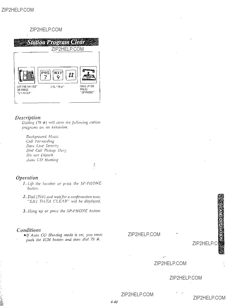
Description
Difllitlg (79 #) lvill clear the jbllorvitlg stariorl program otz an estemiotz.
Backgrormcl Mllsic
Cull For\varditlg
Dtrta Litle
L>ictl Cflll Pickup Detf)
Do tlot Distrtrb
Auto CO Hunting
Operutiorz
1.LifI rhe hcrtlclset or
2.Dial (79#) ad wnit for n confirmation tone. ???EXT DATA CLEAR??? will be displayed.
3.Hang up or press the
Conditions
*If Auto CO Hunting mode is set, you tnust push the LCM button and then dial 79 #.
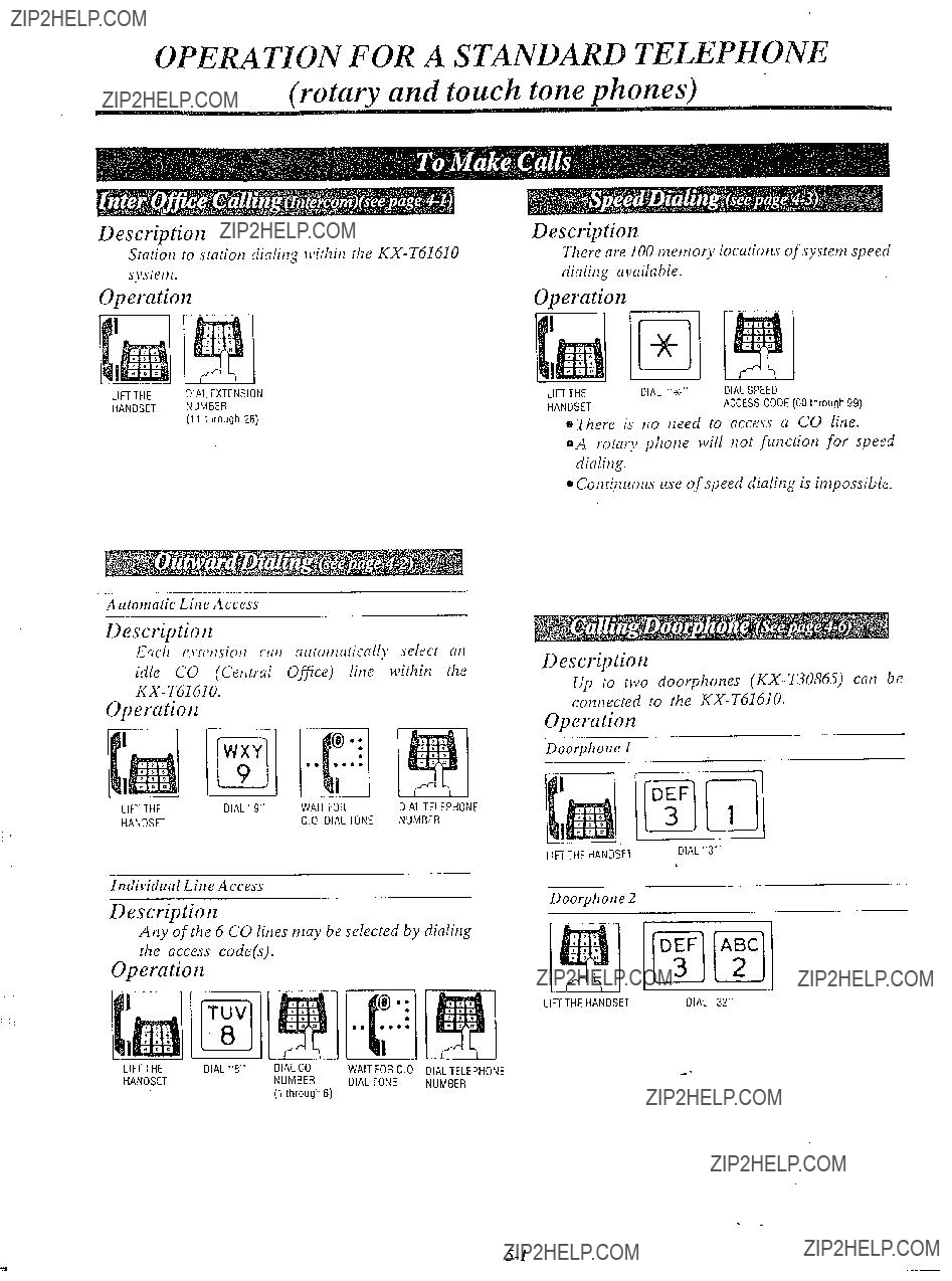
OPERATION FOR A STANDARD TELEPHONE (rotary and touch tone phones)
Descriptiolz
Srariott 10 srariotl dialirq \\firhitl rhe
Ope>ation
LIFTTHE DIALEXTENSION
HANDSET NUMBER
(11 through 26)
Description
There are 100 tnetnory locariom of sysretn speed dialitlg available.
Operation
eThere is no tleed to access a CO line.
oA rotary photze lvill trot function for speed dialing.
@CotlGtlrlorcs use of speed dialing is impossible.
A rdomatic Line Access
Description
Each cxlrttsiott cat1 airrntttaricall~ select cltl idle CO (CetWal Ofice) line withitl the
Operation
Individual Line .4ccess
Description
Any of the 6 CO lines may be selected by dialing the access code(s).
Operation
Description
Up to two doorphones
Operation
Doorphone 1
~~
Doorphone 2
LIFTTHEHANOSETDlAL"32"
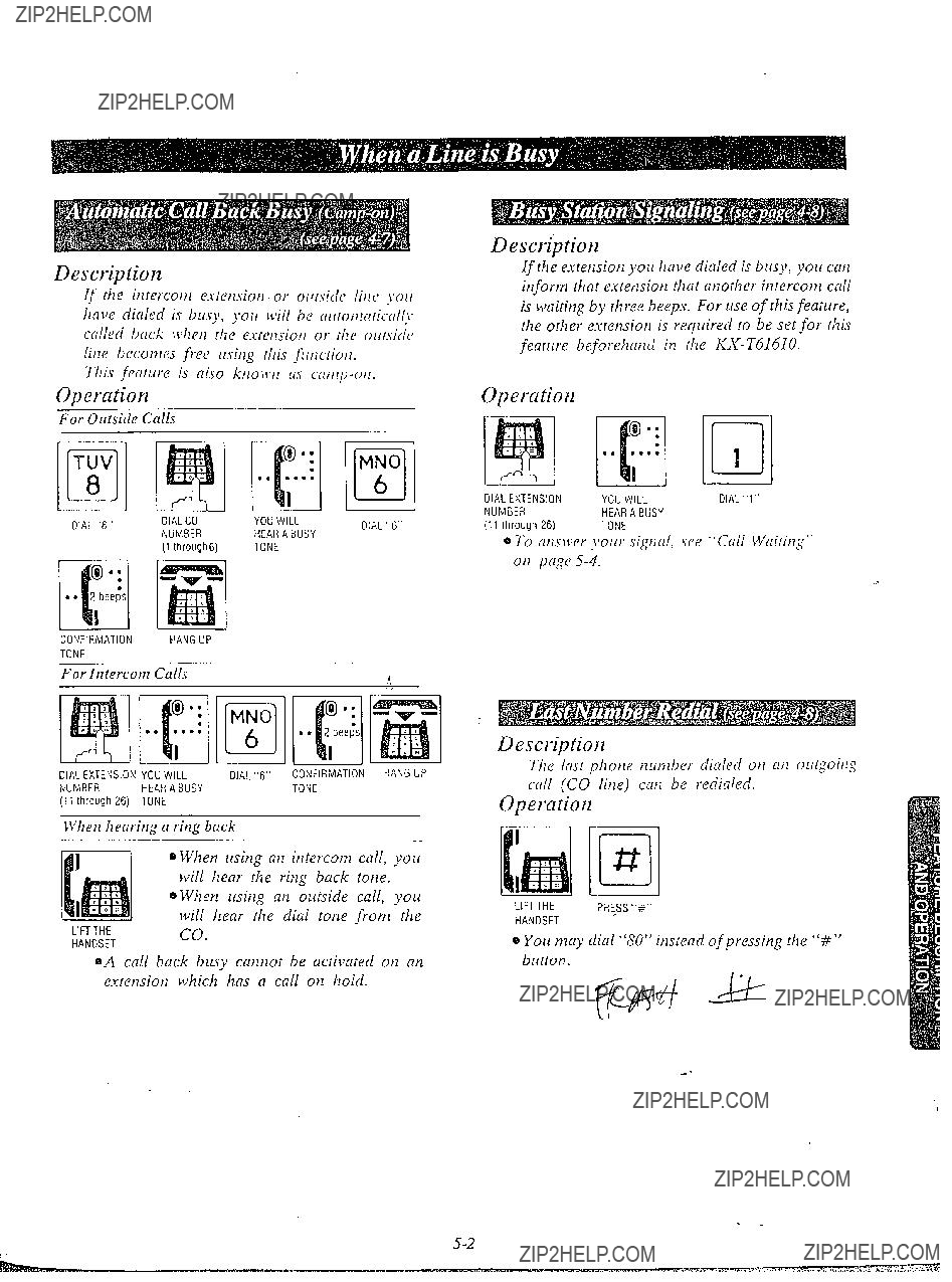
Description
If the iiltercom csterisio~i or orraidc lilic> ~???orc have dialed is buy, you will he (rlrtolllrllic.(rII~. called back \vhe,l the estemiolr or the orrr.vitIv liue becomes free rrsiug this f/rllctiolr.
Tl7i.sferirrrre is also kr70\\???/7 us
Operation
CONFIRMATION HANGUP
TONE
0 When using an intercom call, you will hear the ring back tone.
0 When using an outside call, you will hear the dial tone from the
LIFTTHEco.
HANDSET
oA call back busy catlnot be activated on an eslerlsiorl which has a call ot1 hold.
Description
if the exterzsion you have dialed is blisy, you call ir~form that esfensiou that another intercom call is waiting by three beeps. For use of this feature, the other exrension is required to be set for rhis feature beforehand in the
Operutioil
Description
The last phor7e ,zLr,77berdialed OH aI7 o!rtSoiq ~~711(CO liue) can be redialecl.
Opemtioiz #
La
LIFTTHEPRE_SS"+"
HANDSET
0 You may dial ???80??? instead of pressing the ???#I??? button.
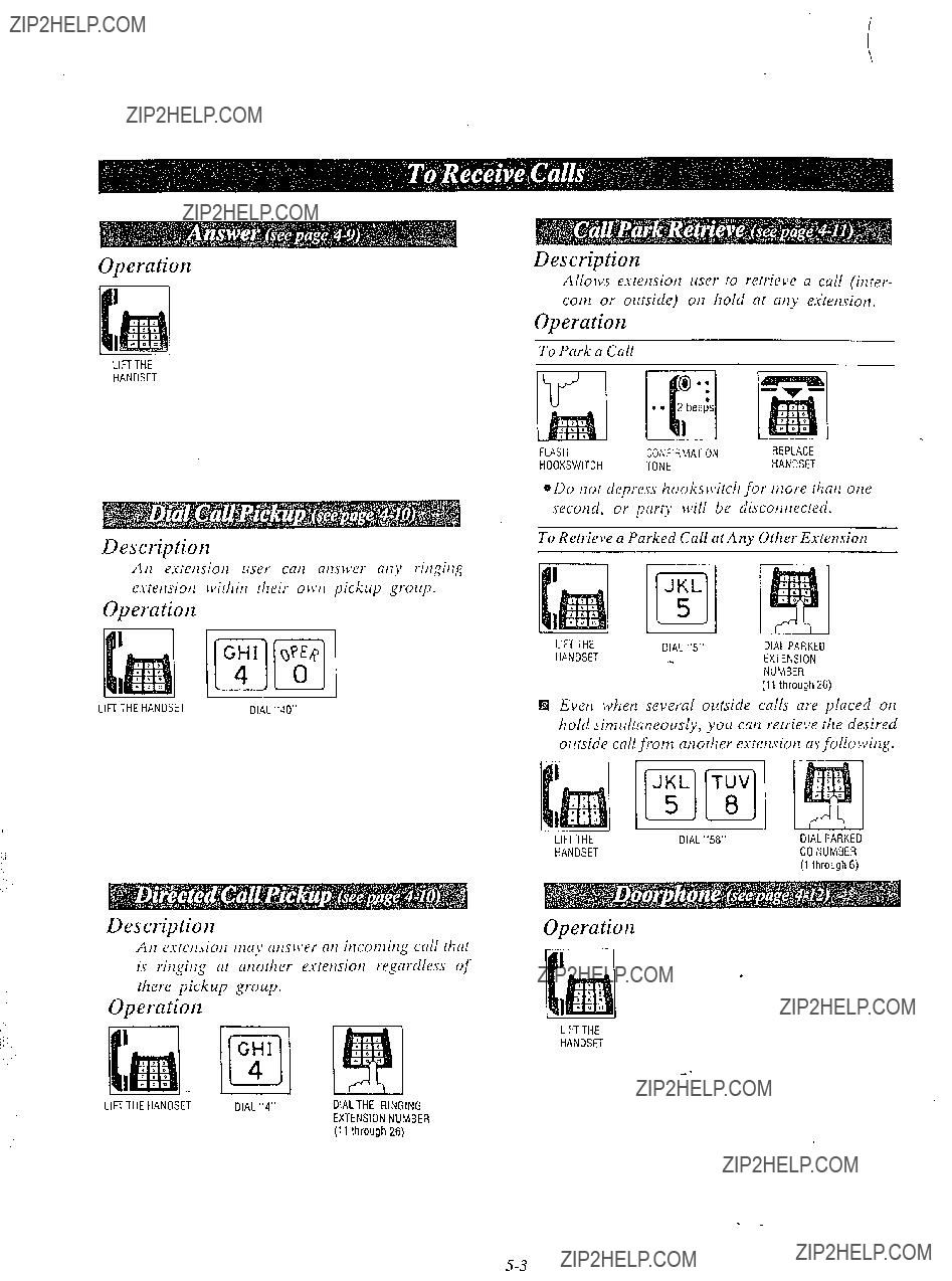
Operation
LIFTTHE
HANDSET
Description
At2 estetlsiotz liser cat? nturver fltijl ritfgitig esretfsiotr \c~ir/iitf [heir o\\???tz pickup groilp.
Operation
LIFITHEHANDSETDlAL"40"
Description
Ati esrctlsiotl ttia>aatw\ser ati iticot7iiti.g call Ihat is ritigitfg af atlorlier esretfsioti regardless of there pickup group.
Operation
Description
Allows esretuiotl uses lo retrieve a call (ititer- cot71 or ourside) oti hold fit atiy e,<tetuiotz.
Operation
To Park a Call
*Do tlof depress hookslvitch for ttiore thnti otie secotld, or prty n:ill be discotltlecred.
To Retrielle a Parked Call at Any 01her Extemiot~
El Ever1 when several outside calls are placed otz hold sitnultatleously, you cats retrieve the desired outside call from another esretuion as followitzg,
Operation
LIFTTHE
HANDSET
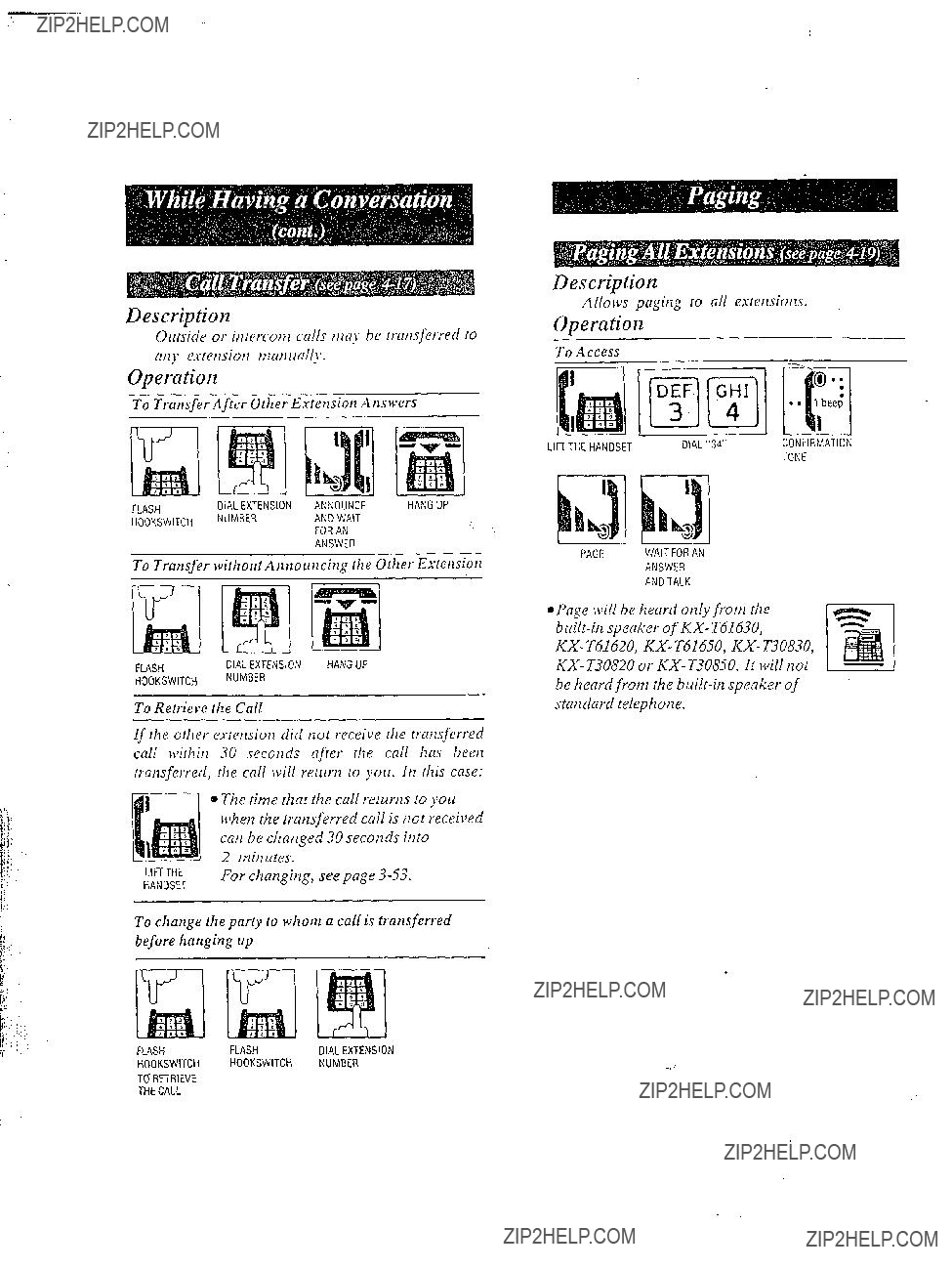


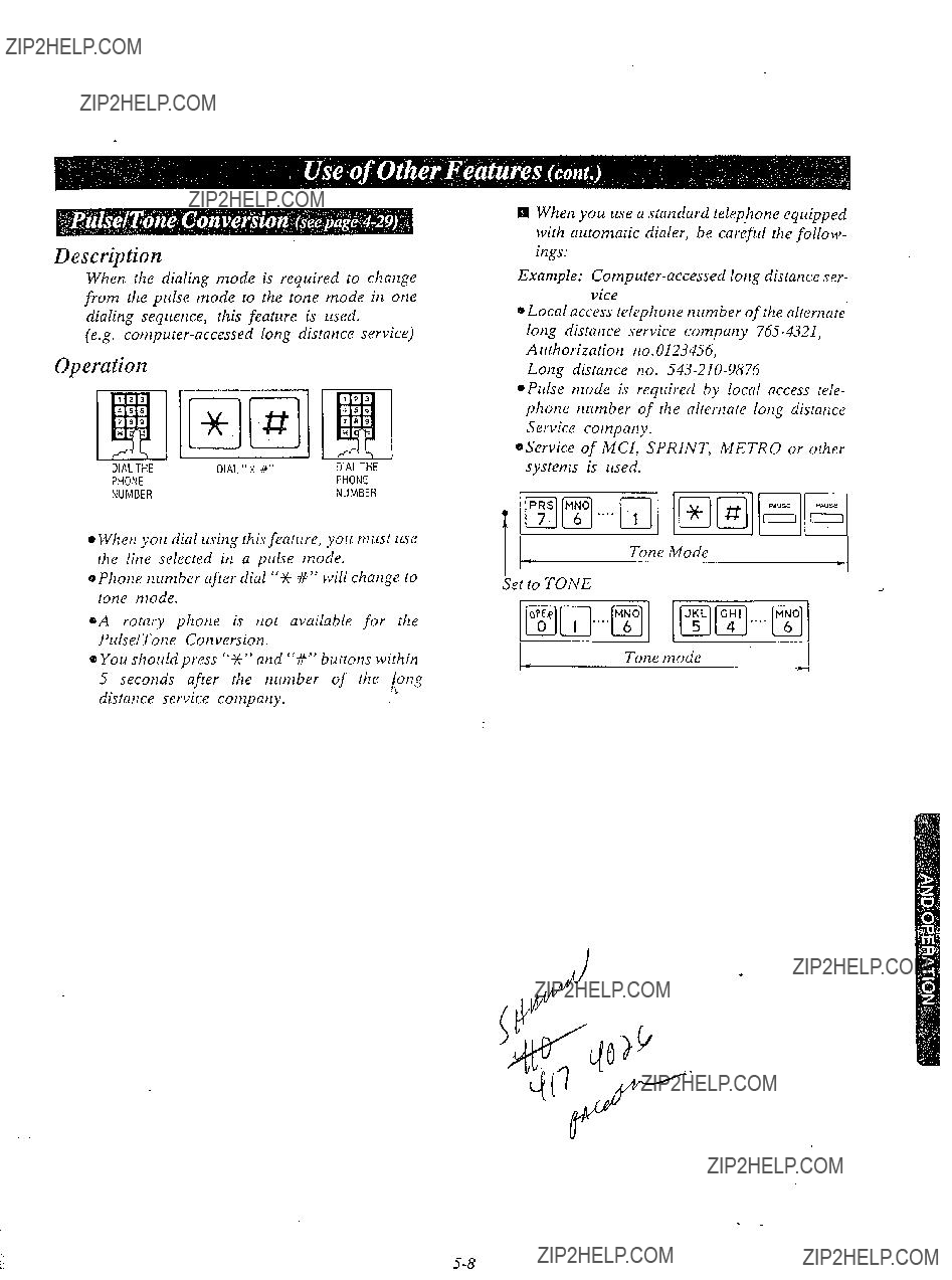

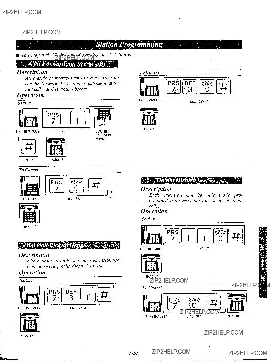
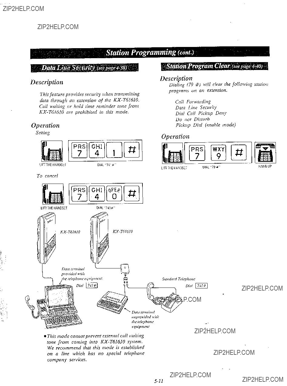


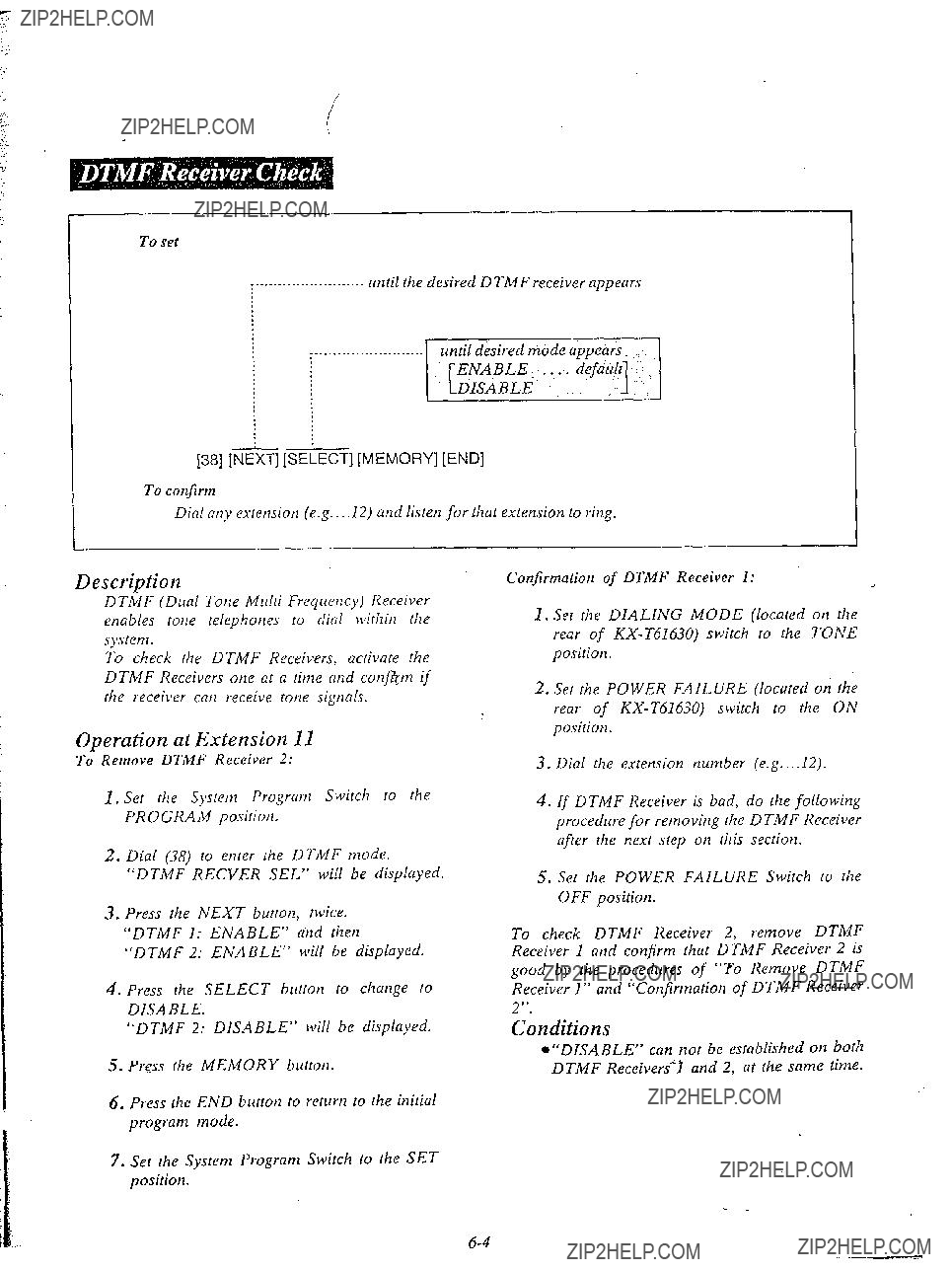
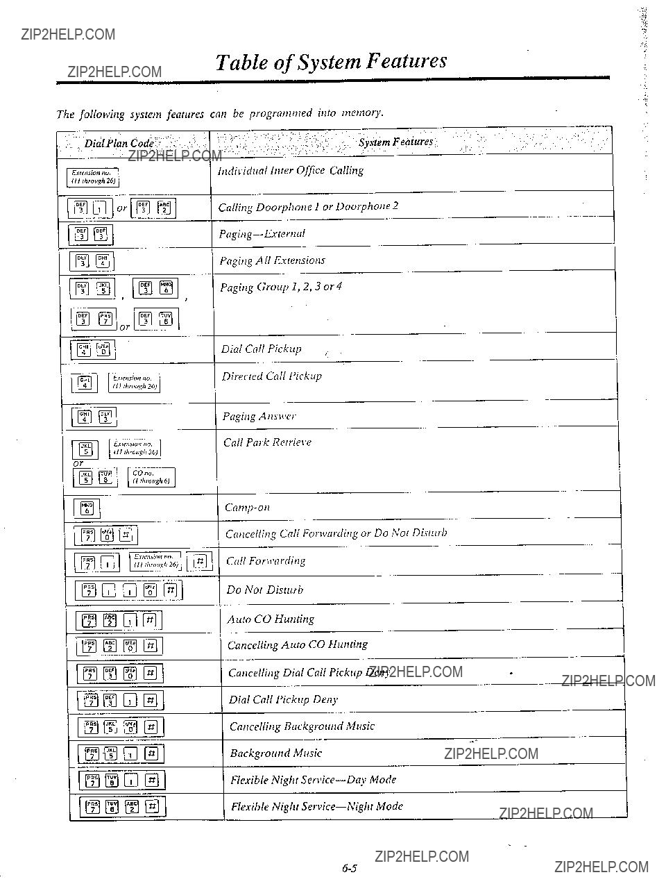


OTHERS
l Keep the unit away from heating appliances and electrical noise generating devices such as fluorescent lamps, motors and television. These noise sources cm interfere _ with the performance of the
l This unit should be kept free of dust, moisture, high temperature and vibration, and should not be exposed to direct sunlight.
ONever attempt to insert wires, pins, etc. into the vents or other holes of this unit.
???If there is trouble, disconnect the unit from the telephone line, Plug the telephone directly into the telephone line. If the telephone operates properly, do nor reconnect the unit to the line until the trouble has been repaired by an authorized Panasonic Factory Service Center. If the telephone does not operate properly, chances are that the trouble is in the telephone system, and not in the unit.
QDO not use benzine, thinner, or similar solvents. Do not ltse abrasive powder to clean the cabinet. Wipe it with a soft cloth.
???/ .
WARNING: TO PREVENT FIRE OR SHOCK HAZARD, DO h???OT
EXPOSE THIS PRODUCT TO RAIN OR MOISTURE.
1

LIMITED WARRANTY
Panasonic Company or Panasonic Sales Company (collectively referred to as ???PANASONIC???) will repair this product with new or rebuilt parts, free of charge, in the U.S.A. or Puerto Rico for one (1) year from the date of original purchase in the event of a defect in materials or workmanship.
Batteries (if
This warranty is extended only to the original purchaser. A purchase receipt or other proof of date of original purchase will be required before warranty performance is rendered.
This warranty only covers failures due to defects in materials or workmanship which occur during normal use. It does not cover damage which occurs in shipment or failures which are caused by products not supplied by Panasonic Company, Panasonic Sales Company or failures which result from accident, misuse, abuse, neglect, mishandling, misapplication, alteratibn, faulty installation, modification, or service by anyone other than a MSC Factory Servicenter or authorized MSC Servicenter or damage that is attributable to acts of God.
LIIMITS AND EXCLUSIONS
There are no express warranties except as listed above.
PANASONIC COMPANY AND PANASONIC SALES COMPANY SHALL
NOT BE LIABLE FOR INCIDENTAL OR CONSEQUENTIAL DAMAGES RESULTIhlG FROM THE USE OF THIS PRODUCT, OR ARISING OUT OF
ANY BREACH OF THIS WARRANTY.
ALL EXPRESS AND IMPLIED WARRANTIES, INCLUDING THE WAR-
RANTIES OF MERCHANTABILITY AND FITNESS FOR A PARTICULAR
PURPOSE, ARE LIMITED TO THE APPLICABLE WARRANTY PERIOD
SET FORTH ABOVE.
Some states do not allow the exclusion or limitation of incidental or consequential damages, or limitations on how long an implied warranty lasts, so the above exclusions or limitations ma,y not apply to you.
This warranty gives you specific legal rights and you may also have other rights which vary from state to state.
If a problem with this product develops during the warranty period, you may contact
your dealer or Servicenter. If the problem is not handled to your satisfaction, then . write to the Consumer Affairs Division at the company address indicated on the back
cover.


Panasonic
.SPEED DIALING4


ELECTRONIC MODULAR SW ITCHING???SYSTEM
K%T61610
Please read this Manual first and then another Installation Manual for programming.
This manual is available for
D
B . . 0EASA-PHONE
MODEL NO.
TELEPHONE EDUIPMENT
LJ
Note:
1.For
2.For
3.For the Features of Flexible keys, refer to this manual.
4.Extension 11 should be connected to
5.All the programming procedures described in the Installation Manual have been modified. Delete step 2 YPress the NEXT button??? from every feature of the programming in another Installation Manual. For further detqil, see page 3 of this manual. This rnaaual describes the
revised procedures from which step 2 has already been deleted.


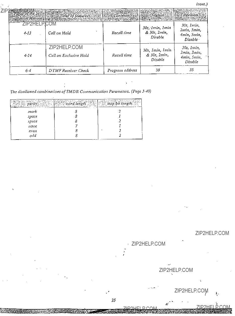


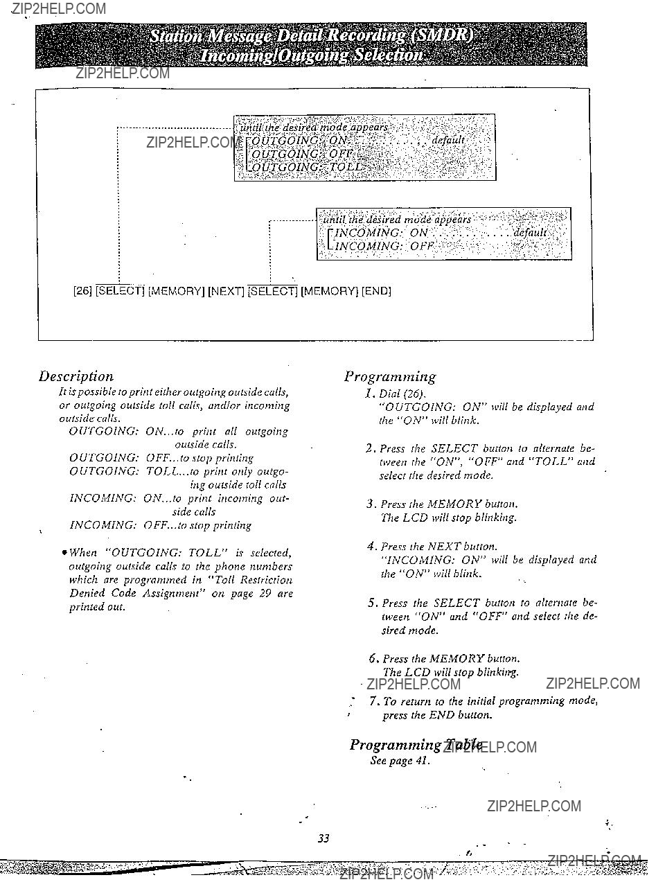


Canceled Features
The listed features are canceled from
..
#