AJ8R

J8 SWITCHES WITH

POWER ROCKER SWITCH TRIP FUNCTION

UPGRADED TYPE

FEATURES

1. Power switches with an electromag- netic reset function which meet the need for energy savings in equipment and for safety.

Applications for these switches include promoting energy savings in equipment (by reducing power consumption when OA equipment is in standby mode, for example), preventing ???res caused by overheating of a heater inside equipment, preventing electrical leaks, and automati- cally turning off the power if the unit tips over or is shaken. These switches feature a built-in electromagnetic reset function

that shuts off the main power supply in response to a signal that is received from an external sensor.

2. A dramatic upgrade in operation feelings

These switches provide the same comfortable operation feelings our conventional J8 switches.

??? Comparison of feel when switch is turned on

Conventional type

Upgraded type

Force

Stroke

3. CT terminals adopted for coil termi- nals

These switches can be used with AMP's CT connectors, which are widely used for wiring connections in OA equipment,

making it possible to achieve greater ef???- ciency in wiring work.

Receptacle for AMP's CT connector

receptacle socket

4.Prolonged electrical service life.

Coil operation provides an electrical life of at least 50,000 switching operations.

5.Assures excellent ability to with- stand inrush current when used to turn a power supply on/off.

The switch uses our own proprietary mechanism that provides an excellent ability to withstand inrush current is employed.

Inrush current rating (IEC65) : 160A (nor- mally 16A at 125V AC), 10,000 times

6.Approved under major international safety standards.

UL, cUL, T??V and SEMKO approved.
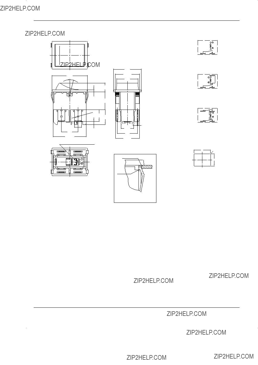
OPERATING PRINCIPLE

???Manual operation is a repetition of (A) and (B) .

This operation is independent of the electromagnetic reset function.

???The reset mechanism operates only when an electromagnetic reset has occurred. (C)

AJ8R

ORDERING INFORMATION

Remarks: 1. They come with a stamp indicating international standards without your request. 2. The color of I O indication on the actuator is white.

PRODUCT TYPES

Remarks: Standard actuator color is dark gray and black. To order switches with a black actuator, replace the letter "Z" with "B" in the product numbers shown below when ordering.

1. Without indication on actuators (Actuator color: Dark gray)

(Ex.)

AJ8R1001ZC (Actuator color: Dark gray Flange color: Dark gray)

??? AJ8R1001BC (Actuator color: Black Flange color: Dark gray)

2. With |O indications on actuators (Actuator color: Dark gray)

3. With -O indications on actuators (Actuator color: Dark gray)

6

03/2005

AJ8R

SPECIFICATIONS

1. Contact rating

Remark: The motor load is in accordance with EN61058-1. Inrush current can be switched up to the value of 6 times the indicated rating.

2. Coil rating

Remark: If the rated voltage is applied to the coil for more than ten seconds or the maximum voltage is applied for more than one second, coil perfor- mance will deteriorate.

3. Characteristics

Remark: Test conditions are in accordance with EN61058-1,UL1054 and JIS C 6571

7

03/2005

AJ8R

DIMENSIONS

Double pole (ON-OFF)

Wiring diagram(Bottom view) Single pole (ON-OFF)

ON (set): 1-2

8.6

.339

Suitable connector: CT connector

25

.984

22+0

???0.2

+0

???.008.866

19.7

.776

0.8 (11.3) .031 (.445)

18.3

.720

21.7??0.25

.854??.010

Opening radius

Edge

The opening radius from when the panel was processed should be on the front side of the panel

Single pole (ON-ON)

Reset: 1-4 closed

Set: 1-2 closed

Double pole (ON-OFF)

ON (set): 1-2 closed 3-4 closed

Diagram of recommended locations for panel mounting holes

Remark: Contact us if you are considering using a panel of other than the rec- ommended size and shape.

Remarks: 1. The external dimensions and mounting dimensions for the single pole, single throw type and the single pole, double throw type are the same as those for the double pole, single throw type indicated above.

2.The ???gures show the double pole, single throw (ON-OFF) type as an example. The contact terminals are 1, 2, 3, and 4.

In the case of the single pole, single throw (ON-OFF) type, the contact terminals are 1 and 2.

In the case of the single pole, double throw (ON-ON) type, the contact terminals are 1, 2, and 4.

There are no other terminals.

Refer to the internal wiring diagram.

3.The coil is a polarized coil; coil terminal 5 is positive and coil terminal 6 is negative.

8

03/2005

AJ8R

NOTES

1.Operating voltage application time

If the rated voltage is applied to the coil for more than 10 seconds or the maxi- mum voltage is applied for more than 1 second, coil performance may deterio- rate.

2.The shape of the mounting panel should be as recommended in the dimensions diagram.

Contact us if you are considering using a panel of other than the recommended size and shape.

3.The mounting panel should be made of SPCC. If a different material is used, its adhesion to the switch unit may be not be as strong. Check this on site if necessary.

4.Note that the actuator could pop out of the switch housing if 19.6N (2kgf) or more of force is applied to the side of the actuator.

(1) When connecting the tab terminals, use a .250 receptacle and insert the ter- minals straight in.

If you insert them at an angle, the termi- nals could catch on the opening and will require greater insertion force.

(2) The coil terminals have speci???c polar- ities. Make sure you connect them cor- rectly.

(3)Use a receptacle that is compliant with JIS C 2809.

In addition, there is some deviation regarding the insertion force depending on the model used from different manu- facturers, so the insertion force should be checked under realistic conditions.

(4)Use AMP's CT connector for the coil terminals.

6. Because special receptacle termi- nals are used for the contact terminals and the common terminals, do not attempt to solder them. Doing so could melt plastic components and otherwise harm the performance of the switch

7. The terminals should be connected in such a way that they are not under constant stress from the connecting wires.

8. Take care not to drop the product as it may impair performance.

9. Resistance to chemicals

To clean the switch unit, use a neutral detergent diluted with water.

Do not use acidic or alkaline solvents as they may damage the switch. Furthermore, be careful not to get any of the detergent solution inside of the switch while cleaning it.

10.This product is not hermetically sealed, so its performance could dete- riorate under certain ambient condi- tions. Avoid using and storing these switches in a location where they will be exposed to corrosive gases, sili- con, or high dust levels, all of which can have an adverse effect on the con- tacts. In addition, because these switches contain permanent magnets, avoid using and storing these switches in a location where metallic dust, etc., is present.

11.When these switches are used with weak currents of 500mA or less, a layer of material on the surface of the contacts may cause contact instabil- ity. Check and evaluate this possibility before using these switches under such conditions.

12.When using an ON-OFF type switch with no (|O) indication on the actuator, the "OFF" position should be indicated on the set in which the switch is installed.

13.To assure reliability, check the switch under actual loading condi- tions. Avoid any situation that may adversely affect switching perfor- mance.

COIL TERMINAL CONNECTOR

Remark: We do not sell this type of connector. Questions concerning this connector should be directed to the manufac- turer.

receptacle socket Pressure welding type: 173977-2: for AWG26, 28 2-179694-2: for AWG24 Crimping type:

179228-2

03/2005