Power Switches
??? Quick Selection Guide
???Power switches described here are not under jurisdiction of the Electrical Appliance and Material Safety Law, but comply with its technical requirements.
??? Explanation of Part Numbers
Power Switches
??? Quick Selection Guide
???Power switches described here are not under jurisdiction of the Electrical Appliance and Material Safety Law, but comply with its technical requirements.
??? Explanation of Part Numbers

Power Switches
??? Product Consolidation
Solder lug Type
PWB Mount Type
Solder lug Type

Power Switches
??? Checklist Before lnquiry
When specifying Power Switches, please take advantage of our standard products for better price and delivery. Please inquire about the following items before ordering.
???Power switches described here are not under jurisdiction of the Electrical Appliance and Material Safety Law (Japan), but comply with its technical requirements.
Notes:
1.When you specify custom types
2.Please inform us if you designate your own part number.
Power Switches
??? Application Notes
When using our Power Switches, please observe the following items (???prohibited items???) and be cautious of the following in order to prevent dangerous accidents and deterioration of performance.
1. Prohibited items and notes on mounting
1.Operation position for soldering (including preheating) Push type switches: Do not solder in the locked condition. Slide type switches: Be sure to switch the lever securely when soldering.
2.When soldering using a soldering iron, soldering conditions vary with the tip shape of the soldering iron, wattage, and PWB thickness. Thoroughly check the conditions in advance, including the heat resistance rating of the solder.
3.Do not apply a load to terminals when soldering. Care should be taken in this regard because a load may deteriorate electric and mechanical characteristics.
4.Since the power switches are not sealed, do not wash them.
5.When mounting a power switch to a
Be sure to check the in???uence as well as the heat resistance rating of the solder.
2. Notes on circuit conditions
1.When a power switch is used with a weak current of less than 500 mA, the ???lm on the surface of contact cannot be broken and contact failure may occur.
2.The durability of power switches varies with the type of the switch: those for ac power and those for dc power. When using switches for ac power, check the durability. When using switches for dc power, review and check the load conditions of a relevant set.
3.Use the switches within their rating, including inrush current rating. Check particularly the inrush current using a switch with a set. Since voltage ???uctuation occurs depending on geographical region, review the derating for using a switch.
4.If load conditions vary in a set to be used, adaptability with the switch must be considered. Be sure to check the above mentioned notes 1 to 3.
3.Prohibited items and notes on mounting and operating conditions
1.In principle, operate the center of the lever.
2.For mounting an operation button:
1)Design so that the button is mounted to the center
Lever
2)Design so that the load in removal and mounting of the button is within the range of the switch???s strength rating of the operational part.
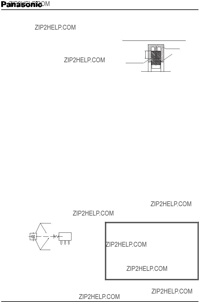
3.Do not pull the switch rod while it is locked. Otherwise, the
the possibility of a breakdown of the locking function. When designing your button, refer to the following shape and dimensions.
Before adopting our switches, check the requirements carefully.
Reference of Customer's button design
Customer's button
(2.5)
Switch rod top
(3.0)
(0.6) (3.3) (0.6)
4.When mounting a switch to a set, check the switch ON/OFF setting and the position of the operational part (slide type, rotary type, etc.).
5.Design and use so that external stress is not continuously applied to the soldering parts (solder lugs and PWB terminals) with a switch mounted in a set.
6.In actual operating conditions, do not use switches under ambient temperatures above 70 ??C.
7.Avoid the following ambient surroundings and other conditions because they may affect performance:
???Under an atmosphere of corrosive gas such as Cl2, H2S, NOx, or SO2
???In atmospheres of residual water drops, dew condensation, or adhesive water drops
???In liquids such as water, salt solution, oil, chemicals, and organic solvents
???In direct sunlight
???In dusty locations
4. Prohibited items and notes on storage conditions
Since contact characteristics and soldering quality may deteriorate due to sulfuration and oxidation of contacts and terminals, pay heed to the following items.
1.For storage and transport of the switches, avoid unpacking them, and store them at room temperature and room humidity. Use them as soon as possible, generally within 3 months, or within a maximum of 6 months after delivery.
2.Do not store the switches under conditions of high temperature and/or high humidity, or in a location where corrosive gas may be generated.
3.If some units remain after unpacking, store them after applying adequate moisture - proof and gas - proof treatment.
5.For use in equipment for which safety requested
Although care is taken to ensure switch quality, variation of contact resistance (increase), short circuits, open circuits, and temperature rise are
some problems that might be generated.
To design a set which places maximum emphasis on safety, review the affect of any single fault of a switch in advance and perform virtually
1.preparing a protective circuit or a protective device to improve system safety, and
2.preparing a redundant circuit to improve system safety so that the single fault of a switch does not cause a dangerous situation.
6.For actual use, be sure to refer to ???Product Speci???cations for Information.???
Power Switches
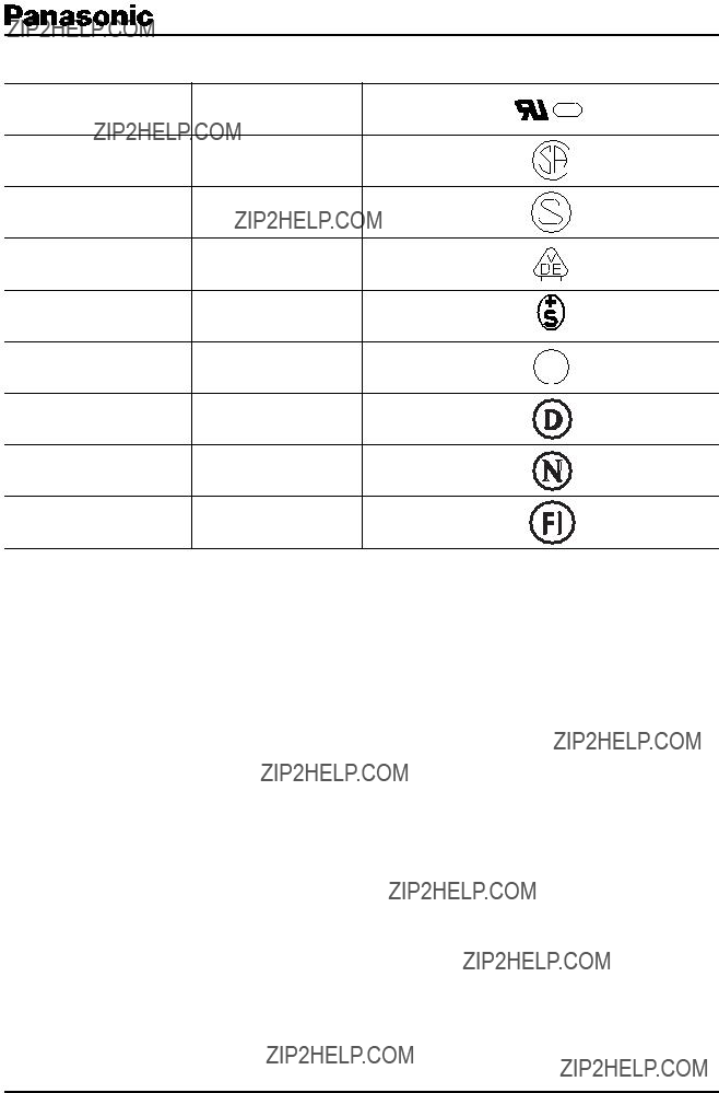
??? Indications of Safety Standard

??? Minimum Quantity/Packing Unit
Please place an order by an integer multiple of the Quantity/Carton.

Power Switches/ESB92
Common Speci???cations for Push Type Power Switches (Series R)
Type: ESB92
??? Mechanical Speci???cations
??? Electrical Speci???cations and Operating Temperature