SUPPLEMENTARY
INSTALLATION INSTRUCTIONS
Ventilating Fan
(Contractor Pack)
Model No. FV-08VSLA2
Contents
General Safety lnformation
Unpacking
Supplied Accessories
Wiring Diagram
lnstallation  (Joist Mounting- ) lnstallation
 (Joist Mounting-
 ) lnstallation
 (
( -Joist Mounting)
lnstallation (Between Joist Mounting) lnstallation
 (Wooden Header)
lnstallation (ln Existing Construction)
Product Service
2-3
3
4
4
5-7
7-8
9
9-10
11
Back cover
Back cover
Applicable to Model:
FV-08VSL2, FV-10VSL2
READ AND SAVE THESE INSTRUCTIONS
Thank you very much for having purchased our product.
Please read these instructions carefully before attempting to install, operate or service the Panasonic product. Failure to comply with instructions could result in personal injury or property damage. Please explain to users how to operate and maintain the product after installation, and this booklet should be presented to users.
Please retain this booklet for future reference.

GENERAL SAFETY INFORMATION
WARNING:
To reduce the risk of fire, electric shock or injury to persons, observe the following:
1.Use this unit only in the manner intended by the manufacturer. lf you have any questions, contact the manufacturer.
2.Before servicing or cleaning unit, switch power off at service panel and lock the service disconnecting means to prevent power from being switched on accidentally. When the service disconnecting means cannot be locked, securely fasten a prominent warning device, such as a tag, to the service panel.
3.Installation work and electrical wiring must be done by qualified person (s) in accordance with all applicable codes and standards, including fire-rated construction.
4.Sufficient air is needed for proper combustion and exhausting of gases through the flue (chimney) of fuel burning equipment to prevent back drafting. Follow the heating equipment manufacturer's guideline and safety standards such as those published by the National Fire Protection Association (NFPA), and the American Society for Heating, Refrigeration and Air Conditioning Engineers (ASHRAE) and the local code authorities.
5.When cutting or drilling into wall or ceiling, do not damage electrical wiring and other hidden utilities.
6.Ducted fans must always be vented to the outdoors.
7.If this unit is to be installed over a tub or shower, it must be marked as appropriate for the application and be connected to a GFCI (Ground Fault Circuit lnterrupter) - protected branch circuit.
8.These models are UL listed for tub and shower enclosures.
9.Do not use this fan with any solid-state speed control device.
10.Canada only: Not to be installed in a ceiling thermally insulated to a value greater than R40.
11.Do not disassemble the unit for reconstruction. lt may cause fire or electric shock.
12.A statement to the effect that when the product is to no longer be used, it must not be left in place but removed, to prevent it from possibly falling.
13.Ceiling joist must be subjected to static load more than five times the weight of the product.
14. The special-purpose or dedicated parts, such as mounting fixtures, must be used if such parts are provided.
15.Do not install the product as the method which is not approved in the instruction.
16.This product must be properly grounded.
17.The Housing Can FV-08VSLA2 must be installed with Motor/Light Kit/Grille Assembly FV-08VSLB2 or FV-10VSLB2 that are marked on their Cartons to indicate the suitability with this model.
Other Motor/Light Kit/Grille Assembly cannot be substituted.
GENERAL SAFETY INFORMATION CONTINUED
CAUTION:
1.Do not install this ventilating fan where interior room temperature may exceed 104 F (40 C).
2.Make sure that the electric service supply voltage is AC 120V, 60 Hz.
3.Follow all local electrical and safety codes, as well as the National Electrical Code (NEC) and the Occupation Safety and Health Act (OSHA).
4.Always disconnect the power source before working on or near the fan, motor, light fixture or junction box.
5.Protect the supply wiring from sharp edges, oil, grease, hot surfaces, chemicals or other objects.
6.Do not kink the supply wiring.
7.Provide make up air for proper ventilation.
8.For general ventilating use only. Do not use to exhaust hazardous or explosive materials and vapors.
9.Do not install the unit where ducts are configured as shown in Fig. A.
Adaptor
Fig. A
10. Not for use in cooking area. (Fig. B)
(Cooking area)
Do not install above or inside this area
 45
45
Cooking Floor equipment
Fig. B
UNPACKING
Unpack and carefully remove unit from carton.
Refer to the Supplied Accessories list to verify that all parts are present.
SUPPLIED ACCESSORIES (4 sets)
(A) For Motor/ Light Kit/ Grille Assembly of model: FV-08VSLB2, FV-10VSLB2
(B) For Housing Can of model: FV-08VSLA2
WIRING DIAGRAM
IMPORTANT:
Remove the tape from damper and adaptor before installation. As shown below:
 Fan body
Fig. 1
Tape
Adaptor


Damper
2.lnsert the suspension bracket into the fan body and adaptor. (Select the suspension bracket as shown below)
Joists
A=12 inches
Fan body
A=16 inches
Suspension bracket 
Fig. 2-1
Suspension bracket 
Fig. 2-2
A=19.2 inches(vertical joist)
Suspension bracket 
Fan body
A=24 inches
Suspension bracket 
Suspension bracket 
Suspension bracket 
Fig. 2-3
Suspension bracket
Suspension bracket 
Suspension bracket 
INSTALLATION  (JOIST MOUNTING-
  ) CONTINUED
4 Long screws (ST4.2X20)
A=10 1/4~12 inches
6.Refer to wiring diagram (page 4).
Using wire nuts, connect house power wires to ventilating fan wires and lighting unit wires: black to black; white to white; green to green; Replace the junction box cover. (Fig.5)
CAUTION:
Mount junction box cover carefully so that lead wires are not pinched.
7.Squeeze the circular duct to fit the adaptor, then slipped onto the adaptor and secure it with duct tape.
 Joist
Joist
2 Long screws (ST4.2X20)
Fan body
Fig. 3-2

 Joist
Joist
8.Finish ceiling work. Ceiling hole should be aligned with the edge of the flange. (Fig.6)
9.Follow the Fig.12-3,12-4(page 9) and the Fig.6,7 (page 8) of the original installation instruction to complete the Motor/Light Kit/Grille Assembly installation.
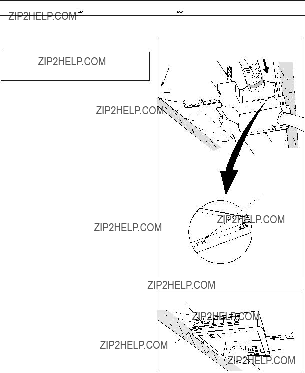
1.Disconnect plug connector from receptacle and remove adaptor from fan body before starting installation.
2.Insert the suspension bracket into the adaptor and secure it to joists by using long screws (ST4.2X20). (Fig.7)
Adaptor
2 Long screws (ST4.2X20)
Joists
CAUTION:
Backside of flange should mount directly to bottom of joist.
If spacing A between joists is 21 1/4 to 23 1/2 inches, connect suspension bracket  and
and  (C4 mark to C4 mark) according to page 5. Select the suspension bracket according to spacing A as shown below.
3.Follow step 5 to 7 of the installation  (page 6) to complete the duct work and wiring.
4.Insert the suspension bracket into fan body (refer to step 2 of Installation  , page 5).
2 Long screws (ST4.2X20)
Adaptor
Suspension bracket
13 1/4~15 1/2(336~394)
16 1/2~18 3/4(419~480)
21 1/4~23 1/2(540~597)
5. Insert the fan body into joists. (Fig.8)
IMPORTANT:
Make sure that adaptor claws are properly inserted into body slots.
6.Secure the fan body to adaptor by using machine screw. (Fig.9)
7.Secure the suspension bracket to joists by using long screws (ST4.2X20) and secure it to fan body by using screw  (ST4.2X12) in vertical direction. (Fig.9)
8.Follow step 8 to 9 of installation  (page 7) to complete the installation work.
Circular duct
Conduit
Joist
Junction box cover
Fan body 
Adaptor claws
Fig. 8
Screw  (ST4.2X12)
Fig. 9
Suspension bracket 
The suspension bracket  can comply with different kinds of
  -joist.
1.Before installation, secure the fan body to adaptor by using machine screw (M4X8). (Fig.1 of page 5)
2.Connect the suspension bracket  to fan body. (Fig.10) (Select the hole by checking
  -joist size fix the screw
to the frame hole.)
3.Connect the ventilating fan to the  -joist. (Fig.11)
4.Follow step 5 to 9 of installation  (page 6~page 7) to complete the installation work.
INSTALLATION  ( BETWEEN JOIST MOUNTING )
1.Before installation, secure the fan body to adaptor by using machine screw (M4X8). (Fig.1 of page 5)
A
 16 inches and 19.2 inches
  horizontal joist
19.2 inches vertical joist
A=16 inches and 19.2 inches horizontal joist
2.Insert the suspension bracket into bracket cover of adaptor side and the back of the fan body. (Fig.12-1,12-2)
(select the suspension bracket according to spacing A as shown right)
INSTALLATION  (BETWEEN JOIST MOUNTING ) CONTINUED
3.Insert the fan body between joists.
Make sure the fan body is level and square (perpendicular) with the joists. (Fig.13)
CAUTION:
Backside of flange should mount directly to bottom of joist.
Joists
Adaptor
Junction box
Fan body
4.Secure the suspension bracket to joists by using long screws (ST4.2X20). (Fig.14, Fig.15)
 Joist
Joist
2 Long screws (ST4.2X20)
5.Secure the suspension bracket to fan body by using screws  (ST4.2X12). (Fig.15)
Fig. 14
6.Follow step 5 to 9 of installation  (page 6~page 7) to complete the installation work.
Joist
Fig. 15
INSTALLATION  (WOODEN HEADER )
1.Before installation, secure the fan body to adaptor by using machine screw (M4X8). (Fig.1 of page 5)
2. Install header between joists by using nails or screws.
Joist
Fan body
Unit: inches (mm)
3. Install the fan body and secure it by using long
INSTALLATION (IN EXISTING CONSTRUCTION )
1.Installation in existing construction.
Installing the fan body in an existing building requires an accessible area (attic or crawl space) above the planning installation location or existing ducting and wiring.
(1)To install the fan body, follow the procedures described in lnstallation . Take the following precautions before installation.
CAUTION:
Check area above planning installation location to be sure that:
1.Duct work can be done and that area is sufficient for proper ventilation.
2.Wiring can be run to planning location.
3.No wiring or other obstructions shall interfere with installation.
(2)Inspect duct work and wiring before proceeding with installation.
(3)Plan suitable location for fan body. (next to ceiling joist)
(4)Before installation, provide inspection and maintenance access at a location that will not interfere with installation work shown in installation 
(5)First, remove ceiling section according to Fig.6 of page 7.
(6)Install fan body.
2.Installation from accessible area above fan location.
(1)Inspect duct work and wiring before proceeding with installation.
(2)Remove ceiling section according to Fig.6 of page 7.
(3)Install fan body.
PRODUCT SERVICE
Warning Concerning Removal of Covers.
The unit should be serviced by qualified technicians only.
Your product is designed and manufactured to ensure a minimum of maintenance.
Should your unit require service or parts, call Panasonic Call Center at 1-866-292-7292 (USA) or 1-800-669-5165 (Canada).
Panasonic Corporation of North America
One Panasonic Way, Secaucus, New Jersey 07094
www.panasonic.com
Panasonic Canada lnc.
5770 Ambler Drive, Mississauga, Ontario L4W 2T3 www.panasonic.ca

 45
45


 (JOIST MOUNTING-
 )
) and
and 
 (C4 mark to C4 mark) as shown below:
 (ST4.2X8)

 (JOIST MOUNTING-
 ) CONTINUED
 (JOIST MOUNTING-
 )
)

 (JOIST MOUNTING-
 ) CONTINUED


 (
(  - JOIST MOUNTING )
