Video Intercom System
Installation and Operation Guide
Model No.
Thank you for purchasing a Panasonic Video Intercom System.
Please read this Installation and Operation Guide before using the unit and save for future reference.
Video Intercom System
Installation and Operation Guide
Model No.
Thank you for purchasing a Panasonic Video Intercom System.
Please read this Installation and Operation Guide before using the unit and save for future reference.

Table of Contents
Important Information
Important safety instructions . . . . . . . . . . . . . . . . . . . . . . . . . . . . . . . . . . . . . . . . . . . . . . . . 3 Additional safety information . . . . . . . . . . . . . . . . . . . . . . . . . . . . . . . . . . . . . . . . . . . . . . . . 5 For best performance. . . . . . . . . . . . . . . . . . . . . . . . . . . . . . . . . . . . . . . . . . . . . . . . . . . . . . 7
Introduction and Installation
Included items . . . . . . . . . . . . . . . . . . . . . . . . . . . . . . . . . . . . . . . . . . . . . . . . . . . . . . . . . . . 8 Compatible Panasonic PBXs . . . . . . . . . . . . . . . . . . . . . . . . . . . . . . . . . . . . . . . . . . . . . . . . 9 Location of controls . . . . . . . . . . . . . . . . . . . . . . . . . . . . . . . . . . . . . . . . . . . . . . . . . . . . . . 10 Before installation. . . . . . . . . . . . . . . . . . . . . . . . . . . . . . . . . . . . . . . . . . . . . . . . . . . . . . . . 13 Installing the door station . . . . . . . . . . . . . . . . . . . . . . . . . . . . . . . . . . . . . . . . . . . . . . . . . . 16 Installing the monitor station . . . . . . . . . . . . . . . . . . . . . . . . . . . . . . . . . . . . . . . . . . . . . . . 20 Using with another machine. . . . . . . . . . . . . . . . . . . . . . . . . . . . . . . . . . . . . . . . . . . . . . . . 27
Using the Unit
Turning {PBX MODE} switch ON/OFF . . . . . . . . . . . . . . . . . . . . . . . . . . . . . . . . . . . . . . . 28 Connecting to a PBX . . . . . . . . . . . . . . . . . . . . . . . . . . . . . . . . . . . . . . . . . . . . . . . . . . . . . 30 Answering a door call. . . . . . . . . . . . . . . . . . . . . . . . . . . . . . . . . . . . . . . . . . . . . . . . . . . . . 31 Monitoring the outside . . . . . . . . . . . . . . . . . . . . . . . . . . . . . . . . . . . . . . . . . . . . . . . . . . . . 34 Opening a door (Door Opener) . . . . . . . . . . . . . . . . . . . . . . . . . . . . . . . . . . . . . . . . . . . . . 35
Help
Troubleshooting . . . . . . . . . . . . . . . . . . . . . . . . . . . . . . . . . . . . . . . . . . . . . . . . . . . . . . . . . 36
Cleaning . . . . . . . . . . . . . . . . . . . . . . . . . . . . . . . . . . . . . . . . . . . . . . . . . . . . . . . . . . . . . . . 37
General Information
Technical data about this product . . . . . . . . . . . . . . . . . . . . . . . . . . . . . . . . . . . . . . . . . . . 38
2
Important Information
The lightning flash with arrow head within a triangle is intended to tell the user that parts inside the product are a risk of electric shock to persons.
The exclamation point within a triangle is intended to tell the user that important operating and servicing instructions are in the papers with the appliance.
Important safety instructions
1)Read these instructions.
All the safety and operating instructions should be read before the appliance is operated.
2)Keep these instructions.
The safety and operating instructions should be retained for future reference.
3)Heed all warnings.
All warnings on the appliance and in the operating instructions should be adhered to.
4)Follow all instructions.
All operating and use instructions should be followed.
5)Do not use this apparatus near water.
For example, near a bathtub, wash bowl, kitchen sink, or laundry tub, in a wet basement, or near a swimming pool, and the like.
6)Clean only with dry cloth.
Do not use liquid cleaners or aerosol cleaners. Use a dry cloth for cleaning.
7)Do not block any ventilation openings.
Install in accordance with the manufacturer???s instructions.
Slots and Openings in the cabinet are provided for ventilation and to ensure reliable operation of the product and to protect it from overheating. The openings should never be blocked by placing the product on a bed, sofa, rug, or other similar surface.
8)Do not install near any heat sources such as radiators, heat registers, stoves, or other apparatus (including amplifiers) that produce heat.
This product should not be placed in a
9)Do not defeat the safety purpose of the polarized or
A polarized plug has two blades with one wider than the other. A grounding type plug has two blades and a third grounding prong. The wide blade or the third prong are provided for your safety. If the provided plug does not fit into your outlet, consult an electrician for
replacement of the obsolete outlet.
10)Protect the power cord from being walked on or pinched particularly at plugs, convenience receptacles, and the point where they exit from the apparatus.
11) Only use attachments / accessories specified by the manufacturer.
3
Important Information
12)Use only with the cart, stand, tripod, bracket, or table specified by the manufacturer, or sold with the apparatus. When a cart is used, use caution when moving the cart / apparatus combination to avoid injury from
Quick stops, excessive force, and uneven surfaces may cause the appliance and cart combination to overturn.
13)Unplug this apparatus during lightning storms or when unused for long periods of time. This will prevent damage to the product due to lightning and
14)Refer all servicing to qualified service personnel. Servicing is required when the apparatus has been damaged in any way, such as power- supply cord or plug is damaged, liquid has been spilled or objects have fallen into the apparatus, the apparatus has been exposed to rain or moisture, does not operate normally, or has been dropped.
SAVE THESE INSTRUCTIONS
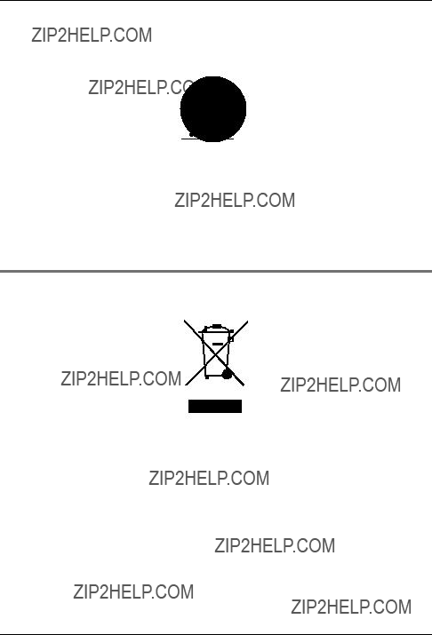
Information on Disposal for Users of Waste Electrical & Electronic Equipment (private households)
This symbol on the products and/or accompanying documents means that used electrical and electronic products should not be mixed with general household waste.
For proper treatment, recovery and recycling, please take these products to designated collection points, where they will be accepted on a free of charge basis. Alternatively, in some countries you may be able to return your products to your local retailer upon the purchase of an equivalent new product.
Disposing of this product correctly will help to save valuable resources and prevent any potential negative effects on human health and the environment which could otherwise arise from inappropriate waste handling. Please contact your local authority for further details of your nearest designated collection point.
Penalties may be applicable for incorrect disposal of this waste, in accordance with national legislation.
4

Important Information
For business users in the European Union
If you wish to discard electrical and electronic equipment, please contact your dealer or supplier for further information.
Information on Disposal in other Countries outside the European Union
This symbol is only valid in the European Union.
If you wish to discard this product, please contact your local authorities or dealer and ask for the correct method of disposal.
Additional safety information
1.Use only the power source marked on the unit. If you are not sure of the type of power supplied to your home, consult your dealer or local power company.
2.Use only the specified AC adaptor.
3.Do not tamper with the plug.
4.Make sure the plug is securely inserted.
5.Do not touch the plug with wet hands.
6.Do not place objects on the power cord. Install the unit where no one can step or trip on the cord.
7.To reduce the risk of electric shock, do not disassemble this unit. Take the unit to an authorised service centre when service is required. Opening or removing covers may expose you to dangerous voltages or other risks. Incorrect reassembly can cause electric shock when the unit is subsequently used.
8.Unplug this unit from household mains supply and refer servicing to an authorised service centre when the following conditions occur:
A.If smoke rises, or an unaccustomed noise or smell is discharged from the unit.
B.If metal objects have been dropped inside the monitor station.
9.Do not put your ear(s) near the speaker, as loud sounds emitted from the speaker may cause hearing impairment.
10.Only a qualified technician is allowed to connect a power cable to the unit. Contact an authorised service centre.
11.Do not make any wiring connections when the power supply is turned on.
12.Never install wiring during a lightning storm.
13.Do not connect a power cable other than the specified voltage.
14.Do not connect the power cable to any terminal other than the one specified.
15.When existing chime wires are used, it is possible that they contain AC voltage. Electric shock or unit damage could result. Contact an authorised service centre.
16.Never touch the inside of the monitor station. High voltage is present.
17.Be sure to install the unit as specified to endure the mass.
18.If the wiring is outdoors, use a protection tube or a surge protector.
19.If the wiring is underground, do not make any connections underground.
20.WARNING ??? To Reduce The Risk Of Fire Or Electric Shock, Do Not Expose This Apparatus To Rain Or Moisture.
21.WARNING ??? Unplug this unit from household mains supply if it emits smoke, an abnormal smell or makes unusual noise. These conditions can cause fire or electric shock. Confirm that smoke has stopped and contact an authorised service centre.
5

Important Information
For your safety
This appliance is supplied with a moulded three pin mains plug for your safety and convenience.
A 3 amp fuse is fitted in this plug.
Should the fuse need to be replaced please ensure that the replacement fuse has a rating of 3 amps and that it is approved by ASTA or BSI to BS1362.
If the plug contains a removable fuse cover you must ensure that it is refitted when the fuse is replaced.
If you lose the fuse cover the plug must not be used until a replacement cover is obtained. A replacement fuse cover can be purchased from your local Panasonic dealer.
IF THE FITTED MOULDED PLUG IS UNSUITABLE FOR THE SOCKET OUTLET IN YOUR
HOME THEN THE FUSE SHOULD BE REMOVED AND THE PLUG CUT OFF AND
DISPOSED OF SAFELY.
THERE IS A DANGER OF SEVERE ELECTRICAL SHOCK IF THE CUT OFF PLUG IS
INSERTED INTO ANY 13 AMP SOCKET.
If a new plug is to be fitted please observe the wiring code as shown below. If in any doubt please consult a qualified electrician.
IMPORTANT:
The wires in this mains lead are coloured in accordance with the following code:
As the colours of the wire in the mains lead of this appliance may not correspond with the coloured markings identifying the terminals in your plug, proceed as follows.
The wire which is coloured BLUE must be connected to the terminal in the plug which is marked with the letter N or coloured BLACK.
The wire which is coloured BROWN must be connected to the terminal in the plug which is marked with letter L or coloured RED.
Under no circumstances should either of these wires be connected to the earth terminal of the three pin plug, marked with the letter E or the Earth symbol  .
.
6
Important Information
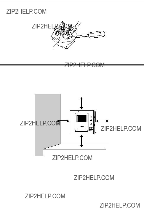
How to replace the fuse: Open the fuse compartment with a screwdriver and replace the fuse (and fuse cover).
FUSE
For best performance
LIf a power failure occurs, the unit will not function.
LDo not place any objects within 20 cm of the monitor station. This may cause communication errors or malfunction.
20 cm
20 cm
LDo not install the unit in places where it will be affected by extremely
7
Introduction and Installation
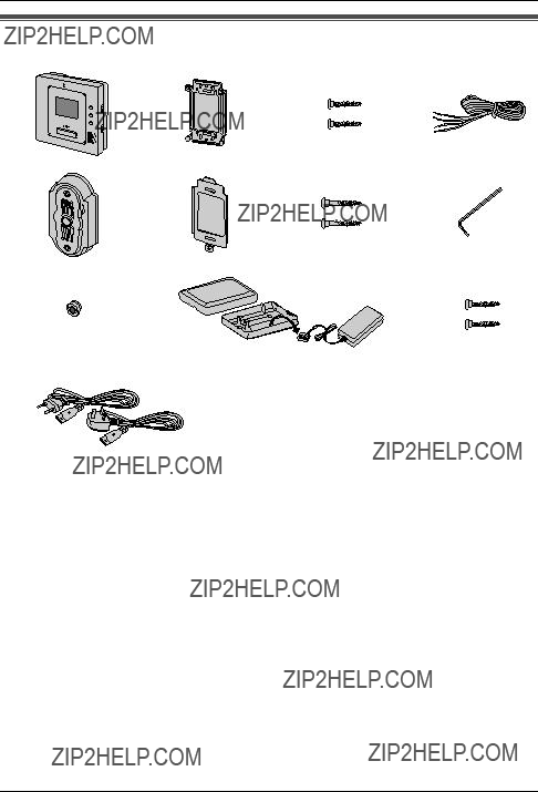
Included items
l
8

Compatible Panasonic PBXs
This unit can be used with Panasonic PBXs (page 27).
Please consult your dealer for compatible PBX information.
For UK and Ireland users:
This unit is compatible with the following Panasonic PBXs*1:
???
???
???
???
???
Compatibility of following Panasonic PBX is depending on software version. Please consult your dealer.
???
???
???
???
*1 As of October, 2005.
For German users:
This unit is compatible with the following Panasonic PBXs*1:
???
Compatibility of following Panasonic PBX is depending on software version. Please consult your dealer.
???
???
???
???
Note:
LThis unit is not compatible with the following doorphone cards.
???
???
9

Introduction and Installation
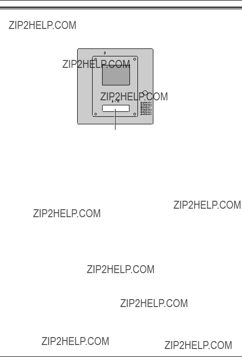
Location of controls
Monitor station
Front viewSide view
A B C
H
Rear view
TALK
D
E
F
G
RINGER
VOLUME
HIGH

LOW 

OFF 

ANSWER
AUTO 

PUSH 

HOLD 

I
J
PBX MODE
OFF ON
K
10
Introduction and Installation
AMicrophone
BDisplay
CMONITOR button
LAllows you to monitor the sound and camera image from the door station (page 34).
D BRIGHT button
LAllows you to adjust the display brightness. 5 levels are available.
E DOOR button
LAllows you to open the door (page 35).
FSpeaker
GTALK button
LTo answer a door call and/or speak to the visitor (page 31).
H Talking indicator
LLights while you are talking.
I RINGER VOLUME switch
LTo adjust the ringer volume. 3 levels (high/low/off) are available.
J ANSWER switch
LTo change the answering mode (page 31).
K PBX MODE switch
LTo connect the unit to a PBX, turn on this switch (page 28).
11
Introduction and Installation
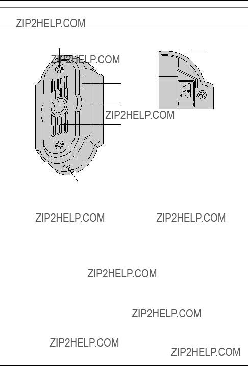
Door station
A
F
B
C
D
E
A Camera
LWhen a visitor presses the Call Button, the camera will turn on and an image of the visitor will be shown on the monitor display.
BMicrophone
CCall Button
LThe Call Button is lighted with a blue LED light while the power is on.
LWhen a visitor presses the Call Button, a ringer tone will ring at the monitor station.
DSpeaker
EWater drain hole
LThis hole allows rain water to drain. Do not cover it.
F Camera angle control lever
LThe camera angle can be adjusted when installing the door station (page 13, 17).
12

Introduction and Installation
Before installation
To avoid malfunction or communication disturbances, do not install either the door station or the monitor station in the following locations:
???Places where vibration or any other kind of impact occurs.
???Places where echoing is frequent.
???Places where a high concentration of dust, hydrogen sulfide, phosphorus, ammonia, sulfur, carbon, acid, or noxious fumes occur.
???Within 2 m of a TV, microwave, personal computer, air conditioner or any other electrical device.
Standard installation position of the door station and camera range
LSide view of when the camera is facing the front at 0??.
LTop view of when the camera is facing the front at 0??.
Image range: 650 mm
L 
R
13

Introduction and Installation
Note:
LThe measurements and angles are for reference purposes and may vary depending on the environment.
LIf a strong light is shining on the door station, the visitor???s face may not be distinguishable. Do not place the door station in the following locations.
???Where most of the background is the sky.
???Where the background is a white wall, and direct sunlight will reflect off it.
???Where direct sunlight will shine on the door station.
???Where echoing occurs, causing the unit to beep frequently.
LMake sure the back of the door station is not subject to water.
Standard installation position of the monitor station
Place the monitor station in a location so that your eyes are the same height as the centre of the display.
Note:
LIn areas surrounded by high electrical field, disturbance may occur in the monitor station???s image or sound.
LBe sure to install the monitor station more than 5 m away from the door station.
LDo not place any objects within 20 cm of the monitor station. This may cause communication errors or malfunction.
LDo not install the monitor station inside a wall.
14
Introduction and Installation
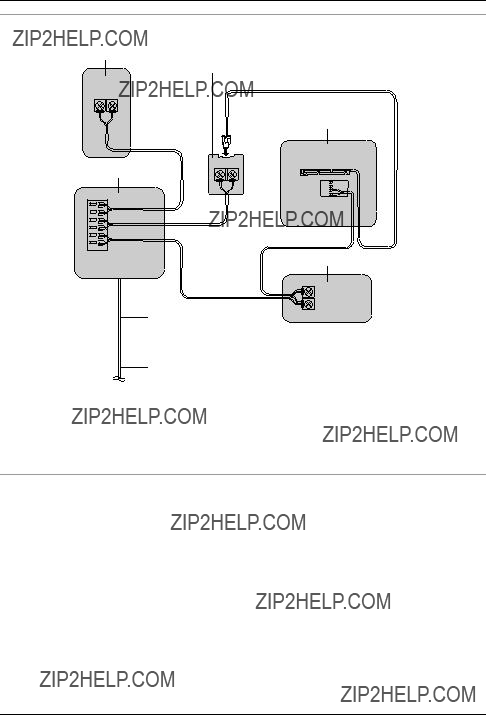
Wiring schematic diagram
Power cable
 AC adaptor
Power cord
Note:
LThe Door Opener wiring schematic diagram is an example. Refer to the wiring instructions provided with your Door Opener and PBX for details.
LRefer to the technical data on page 38 when connecting to a Door Opener.
Power cable/wire type and distance
LPower cable (between the monitor station and the AC adaptor):
Type: ??1.2 Fire alarm cable 16 AWG
Distance: Maximum 30 m
LWire (between the monitor station and the door station):
Type: General cable
Distance: Maximum 100 m
Loop resistance: 18.4 ??? or lower
LWire (between the monitor station and PBX):
Type: General cable
Distance: Maximum 100 m
15
Introduction and Installation
Installing the door station
Make sure to install the door station on a flat, vertical wall.
Important:
LOn the bottom surface of the door station, there is a hole to allow water to drain. Do not cover it up when installing.
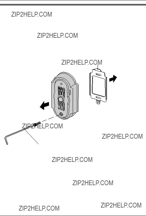
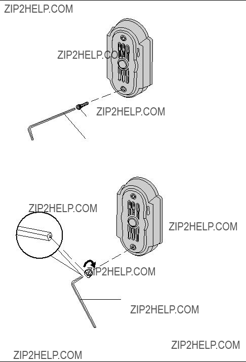
1 Unscrew the
LThe pin hole camera is not a screw to be touched or removed.
Mounting bracket
Pin hole camera 
 Hex-head
(Attached to the door station)
Allen key
16
Introduction and Installation
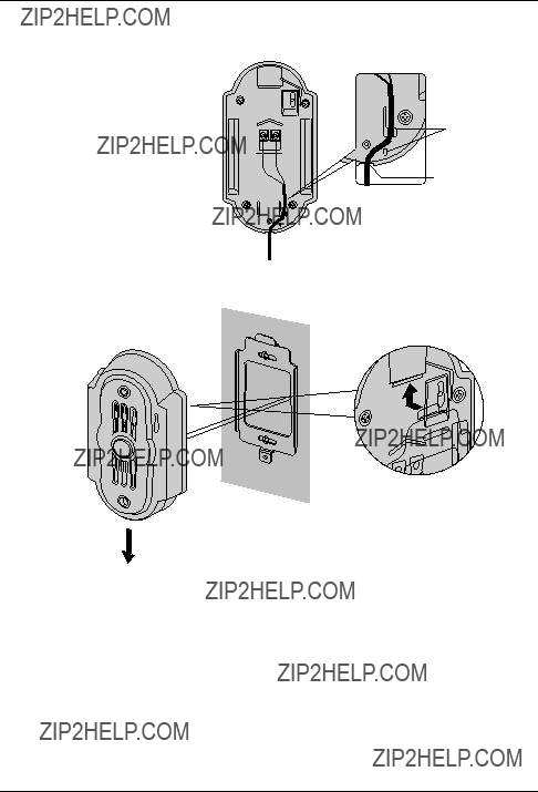
2 Attach the mounting bracket to the wall using the wood screws (3.8 mm x 20 mm). LBefore drilling, see page 13 for installation location.
Mounting bracket
83.5 mm
Wood screws
Wall
Wire (Not included)
3 Connect the wires that connect to the monitor station to the terminal connector by unscrewing the screws, pushing in the wires, then tightly fastening the screws.
LSee page 15 for the wire type and distance.
LYou can change the camera angle using the camera angle control lever. See page 13 for details.
Wire (Not included)
17
Introduction and Installation
LIf you want to connect the wires without them passing through a hole in the wall, connect the wires by passing them through the ribs and the wire hole.
Rib
Wire hole
4 Mount the door station to the mounting bracket.
1
2
Push the door station down until it is secure.
18
Introduction and Installation
5 Insert the
Allen key
6 Attach the bolt cover using the shorter end of the allen key.
LUse protrusion on the shorter end of the allen key to rotate the bolt cover until it is secure.
Allen key
19

Introduction and Installation
Installing the monitor station
Note:
LWhen connecting to a PBX, make sure the {PBX MODE} switch is set to {ON} before installing the monitor station (page 28).
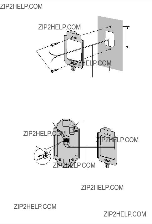
1 Install the mounting bracket to a wall using the wood screws (4 mm x 16 mm). LRemove the mounting bracket from the rear of the monitor station beforehand. LBefore drilling, see page 13 for installation location.
Mounting bracket
83.5 mm
Wood screws
Wall
Wire (Not included)
2 Attach the power cable to the terminal. See page 26 for details on how to attach the power cable.
LIf you want to use your own power cable, see page 15 for the type and distance.

 Terminal (Non polar)
 Power cable
20
Introduction and Installation
3 Attach the wires that connect to the door station to the terminal. See page 26 for details on how to attach the wires.
LSee page 15 for the wire type and distance. LSee the wiring schematic diagram on page 15.
Stripped end of the wire
9 mm Terminal 

(Non polar)
Button
Wire (Not included)
Power cable
LIf you want to connect the wires and the power cable without them passing through a hole in the wall, connect by passing the wires through the wire guide, and the power cable through the power cable guide.
Power cable guide
Wire guide
21
Introduction and Installation
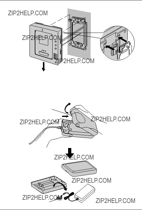
4
5
Mount the monitor station to the mounting bracket.
1
2
Push the monitor station down until it is secure.
Take out the AC adaptor and the DC terminal from the case.
LPush the arrow mark on the front case, then release from the rear case.
LTake out the cardboard and wood screws. The wood screws are necessary when attaching the AC adaptor and the DC terminal to a wall (page 24).
Arrow mark
DC terminal
 AC adaptor
22

Introduction and Installation
6 Connect the power cable to the DC terminal, the power cord to the AC adaptor, then connect the power cord to the AC outlet (100 V ??? 240 V, 50 Hz / 60 Hz).
LBe sure to connect the power cable to the 2 holes on the left side of the DC terminal. LFor details on how to attach the power cable, see page 26.
3
To AC outlet
2
Power cable
 1
1
7 Attach the DC cord to the clamp on the rear of the DC terminal.
LThis will help to avoid the DC cord to disconnect from the DC terminal.
DC terminal
DC cord
Clamp
23

Introduction and Installation
To attach the AC adaptor and the DC terminal to a wall
By placing the AC adaptor and the DC terminal in the case and mounting the case to the wall, you can protect the AC adaptor and the DC terminal from tampering and exposure.
Note:
LDisconnect the DC cord from the clamp on the rear of the DC terminal beforehand. See step 7 on page 23 for details.
LTake out the cardboard and wood screws from the AC case beforehand.
1
2
Attach the rear part of the case to a wall using the wood screws (4 mm x 16 mm).
Case
83.5 mm
Wood screws
Wall
Pack the AC adaptor and DC terminal as shown.
1.Pack the AC adaptor in the rear case.
LBe sure to run the power cord through the power cord hole.
2.Pack the DC cord in the rear case.
LBe sure to bundle the DC cord so that it will not touch the bottom of the case.
3.Pack the DC terminal in the rear case.
LBe sure to run the wires through the wire hole, then under the wire rib.
24

Introduction and Installation
3 Attach the front of the case.
1
2
Note:
LTo open the case again, push the bottom of the front case, then release from the rear case.
25

Introduction and Installation
To attach the power cable
 Button
Button 
Terminal
Terminal connector connector
LWhile pressing on the button with a pointed object such as a screwdriver, insert the power cable into the terminal.
LTo disconnect the power cable, press on the button while pulling out.
LTo attach an optional power cable, cut off about 12 mm of the cable cover (1), then push in firmly until the end of the cable is securely inserted into the power connection terminal (2).
Correct Incorrect
12 mm
To attach the wires
LStrip off of the wire cover so that about 9 mm of the wire is exposed.
LWhile pressing on the button with a pointed object such as a screwdriver, insert the wire into the terminal connector.
LTo disconnect a wire, press on the button while pulling out.
26
Introduction and Installation
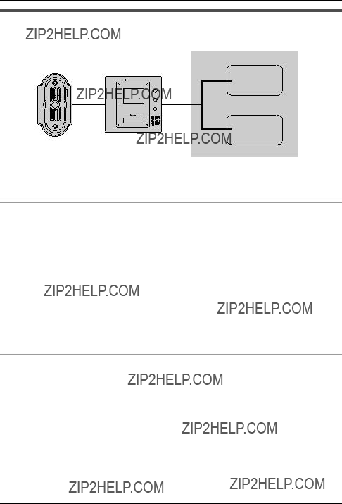
Using with another machine
PBX
Door
(Door Opener)
Note:
LSee page 15 for wiring information.
When connected to a PBX
Connecting to a PBX allows you to answer door calls using additional machines.
Please use only a Panasonic PBX (page 9).
LIf you answer a call from the door station with a PBX extension, the camera image from the door station will be displayed at the monitor station. If the monitor station user tries to answer the call, a beep will sound. The display will turn off when the conversation has ended or when the conversation continued for more than about 3 minutes.
LIf you answer a call from the door station with the monitor station, the call will continue to ring at the extension for about 15 to 30 seconds. If the extension user answers the call while the call is still ringing, the door station user, the monitor station user, and the extension user can speak together.
L{AUTO} mode (page 32) will not function when a door station call is answered by an extension user.
When connected to a door (Door Opener)
Connecting to a door allows you to open the door using the monitor station (page 35).
27
Using the Unit
Turning {PBX MODE} switch ON/OFF
When connecting to a PBX (page 30), turn {PBX MODE} switch on. If not, turn {PBX MODE} switch off. The default setting is {OFF}.
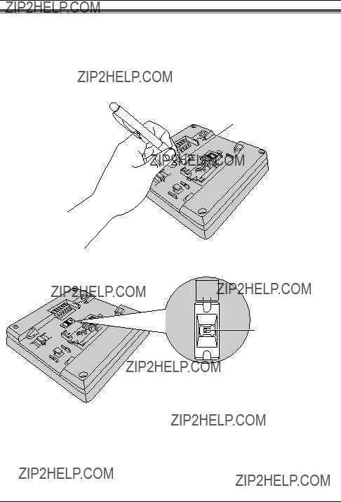
1 Remove the switch cover from the rear of the monitor station. LUse a sharp, thin object such as a mechanical pencil.
Switch cover
2 Select {ON} or {OFF} (default).
PBX MODE
OFF ON
{PBX MODE} switch
28
Using the Unit
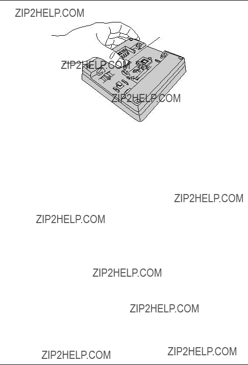
3 Attach the switch cover to the rear of the monitor station.
Switch cover
29
Using the Unit
Connecting to a PBX
Connecting to a PBX allows you to answer door calls from any telephone. See page 15 for wiring information.
Please use only a Panasonic PBX. See page 9 for the PBX model list that is compatible and other optional hardware.
Important:
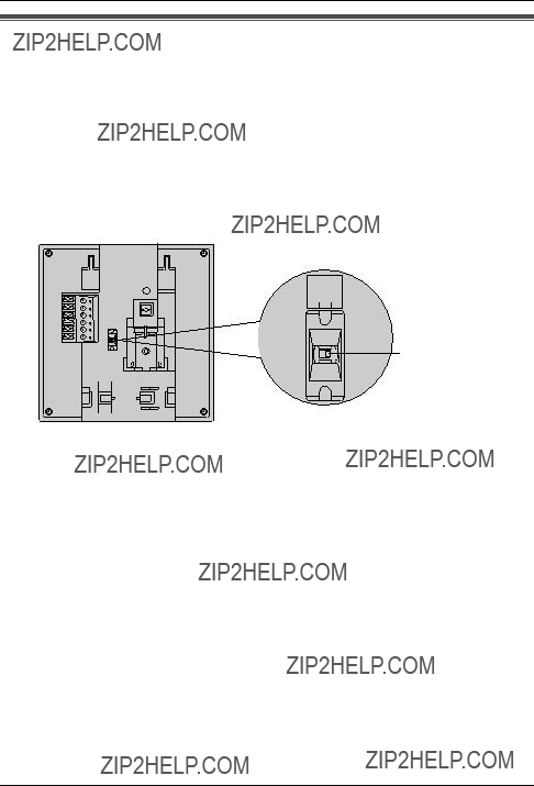
LMake sure {PBX MODE} switch is set to {ON} beforehand (page 28). The default setting is {OFF}.
LIf you connect to a PBX while {PBX MODE} switch is set to {OFF}, voices may be muted for approximately 2 seconds before you can start talking or listening to the caller.
PBX MODE
OFF ON
{PBX MODE} switch
Note:
LIf you answer a call from the door station with a PBX extension, the camera image from the door station will be displayed at the monitor station. If the monitor station user tries to answer the call, a beep will sound. The display will turn off when the conversation has ended or when the conversation continued for more than about 3 minutes.
LIf you answer a call from the door station with the monitor station, the call will continue to ring at the PBX for about 15 to 30 seconds. If the PBX user answers the call while the call is still ringing, the door station user, the monitor station user, and the PBX user can speak together.
30
Using the Unit
Answering a door call
There are 3 ways to answer a door call. Choose the desired mode by changing the {ANSWER} switch position.
Important:
LWhen speaking with a caller, speak in turns. If you and the caller speak at the same time, you will not hear each other.
Microphone {BRIGHT}
ANSWER
AUTO
PUSH 

HOLD
{ANSWER} switch
{TALK}
Talking indicator
Available answer modes
???{AUTO} mode: When a visitor calls you, you can answer the call by voice (page 32).
???{PUSH} mode (default): When a visitor calls you, you can answer the call by pressing {TALK}. You may then speak with the caller (page 32).
???{HOLD} mode: When a visitor calls you, you can answer the call by pressing {TALK}. Press {TALK} while speaking to the caller and release the button to allow the caller to speak to you (page 32).
Note:
LIf the door station is located in a noisy area, {PUSH} mode or {AUTO} mode may not function properly.
31
Using the Unit
{PUSH} mode (Push to talk mode)
1
2
When a ringer tone is heard, press {TALK}.
Speak to the visitor.
3 To end the conversation, press {TALK}. LThe display will turn off.
{AUTO} mode (Auto talk mode)
This mode allows you to answer the call by voice. Speak a brief reply into (or toward) the monitor station, such as ???Yes???? or ???Hello????. This reply is used to start {AUTO} mode; the visitor will not hear your reply. The monitor station will beep to indicate {AUTO} mode has started and you may then speak to the visitor.
1
2
3
When a ringer tone is heard, answer ???Yes???? within 30 seconds.
LA beep will sound to indicate that you can talk to the visitor
Speak to the visitor.
To end the conversation, press {TALK}.
Note:
LMake sure you are within about 50 cm of the monitor station. LYou can also answer the call by pressing {TALK}.
LYour initial reply should be brief (less than 1 second), otherwise {AUTO} mode will not start.
LIf a visitor calls you, a loud, brief sound (such as a barking dog) may start {AUTO} mode even though you have not replied by voice.
{HOLD} mode (Hold to talk mode)
1
2
3
4
When a ringer tone is heard, press and hold {TALK} to speak to the caller. LA beep will sound and the Talking indicator will light.
To listen to the visitor, release {TALK}.
LThe Talking indicator will turn off.
To speak again, press and hold {TALK}.
To end the conversation, tap {TALK}.
Note:
LMake sure you speak to the caller only while pressing {TALK} and release {TALK} when you have stopped speaking so that the caller can speak to you.
32

Using the Unit
Note:
LSpeak clearly about 50 cm away from the microphone.
LWhile the display is on, you can press {BRIGHT} repeatedly to select the desired brightness. If a power failure occurs, the brightness setting will be reset.
LIf you do not answer a door call within 30 seconds, the display will turn off. If you press {TALK} again, the display will turn on again, and you can talk to the visitor.
LThe conversation will be automatically disconnected in about 1 minute and 30 seconds (about 1 minute in {HOLD} mode). To resume the conversation, press {TALK}.
LAt night or when there is not enough lighting in the doorway, the display will be shown in black and white.
33
Using the Unit
Monitoring the outside
You can monitor the sound and camera image from the door station for up to 1 minute at a time.
 {MONITOR}
 {BRIGHT}
{TALK}
1 Press {MONITOR}.
LThe outside image will be shown on the display, and the outside sound will be heard. The inside sound will not be heard at the door station.
LIf necessary, press {BRIGHT} repeatedly to select the desired brightness.
2 To end monitoring, press {MONITOR}.
LEven if you do not press {MONITOR}, monitoring will automatically end in about 1 minute.
Note:
LIf the Call Button is pressed while you are monitoring, the ringer tone will not be heard. LTo talk to the visitor while monitoring, press {TALK}.
34

Using the Unit
Opening a door (Door Opener)
You can open the door using the monitor station (a separate Door Opener is required).
 {DOOR}
1 While the display is on, press and hold {DOOR}.
LThe door will remain open while {DOOR} is pressed.
35

Help
Troubleshooting
36
Cleaning
Clean the unit with a soft, dry cloth when cleaning. For excessive dirt, wipe the unit with a slightly damp cloth.
Important:
LDo not use anything containing alcohol, polish powder, powder soap, benzine, thinner, wax, petroleum, or boiling water. Also do not spray with insecticide, glass cleaner, or hair spray. This could cause a change in colour or quality.
37

General Information
Technical data about this product
Monitor station
Note:
LTo connect to a Door Opener, make sure the Door Opener is:
???Normal open (Low active)
???Less than 30 V AC (1 A), 24 V DC (1 A)
Door station
*1 Supplied from the monitor station.
AC adaptor (Part number: PFAP1014)
38

General Information
Note:
LDesign and specifications are subject to change without notice.
LThe pictures and illustrations in these instructions may vary slightly from the actual product.
39

For your future reference
Date of purchase
Serial number (found on the rear of the unit)
Dealer???s name and address
Dealer???s telephone number
Attach your sales receipt here.
Panasonic Communications Co., Ltd.
Copyright:
LThis material is copyrighted by Panasonic Communications Co., Ltd., and may be reproduced for internal use only. All other reproduction, in whole or in part, is prohibited without the written consent of Panasonic Communications Co., Ltd.
?? 2005 Panasonic Communications Co., Ltd. All Rights Reserved.
PFQX2319ZA DC1005SM1115 1/2