Digital Camera/VTR


 P
P
Operating Instructions
Digital Camera/VTR
P
Operating Instructions

For your safety
CAUTION
RISK OF ELECTRIC SHOCK
DO NOT OPEN
CAUTION: TO REDUCE THE RISK OF ELECTRIC SHOCK,
DO NOT REMOVE COVER (OR BACK).
NO
REFER SERVICING TO QUALIFIED SERVICE PERSONNEL.
The lightning flash with arrowhead symbol, within an equilateral triangle, is intended to alert the user to the presence of uninsulated ???dan- gerous voltage??? within the product???s enclosure that may be of sufficient magnitude to consti- tute a risk of electric shock to persons.
The exclamation point within an equilateral tri- angle is intended to alert the user to the pres- ence of important operating and maintenance
(service) instructions in the literature accompa- nying the appliance.
 RBRC
RBRC
RBRC
ATTENTION:
The product you have purchased is powered by a nickel cadmium battery which is recyclable. At the end of it???s useful life, under various state and local laws, it is illegal to dispose of this battery into your municipal waste stream.
Please call
Memory
Replace battery with part No. CR2032 only.
Use of another battery may present a risk of fire or explosion.
Do not recharge, disassemble or dispose of in fire.
is the safety information.
FCC NOTE:
This device complies with Part 15 of the FCC Rules. To assure continued compliance follow the attached installation instructions and do not make any unauthorized modifications.
This equipment has been tested and found to comply with the limits for a Class A digital device, pursuant to Part 15 of the FCC Rules. These lim- its are designed to provide reasonable protection against harmful interference when the equipment is operated in a commercial environment. This equipment generates, uses, and can radiate ra- dio frequency energy and, if not installed and used in accordance with the instruction manual, may cause harmful interference to radio commu- nications. Operation of this equipment in a resi- dential area is likely to cause harmful interference in which case the user will be required to correct the interference at his own expense.
CAUTION:
TO REDUCE THE RISK OF FIRE OR
SHOCK HAZARD AND ANNOYING INTER-
FERENCE, USE THE RECOMMENDED
ACCESSORIES ONLY.
WARNING:
TO REDUCE THE RISK OF FIRE OR
SHOCK HAZARD, DO NOT EXPOSE THIS
EQUIPMENT TO RAIN OR MOISTURE.
CAUTION:
TO REDUCE THE RISK OF FIRE OR
SHOCK HAZARD, REFER MOUNTING OF
THE OPTIONAL BOARD TO AUTHO-
RIZED SERVICE PERSONNEL.
??? 2 ???

Contents
Bold letters should be set or adjusted immediately after purchase.
??Using the Microphone Kit
(Standard accessory) Mounted
to the Main Unit . . . . . . . . . . . . . . . . . . 37
??Mounting the
Holder (Option) . . . . . . . . . . . . . . . . . . 38
??Using the Microphone not Mounted to
the Main Unit . . . . . . . . . . . . . . . . . . . . 39 ??Mounting a Wireless Microphone . . . . 40
Connecting an Audio Component . . . . . 40
Mounting the Unit to a Tripod . . . . . . . . 41
Adjusting the Shoulder Pad Position . . . 42
Attaching the Rain Cover . . . . . . . . . . . 43
Connecting the
Control Unit (Option) . . . . . . . . . . . . . 44
Warning/Status Displays in the
Viewfinder and Display Window
??Displaying the Setting Menu Inside the
Viewfinder . . . . . . . . . . . . . . . . . . . . . . 45
??Setting Menu Configuration . . . . . . . . 45
??Basic Setting Menu Operations . . . . . 47
Lamp Displays Inside the
Viewfinder . . . . . . . . . . . . . . . . . . . . . 49
??Setting the ! Lamp Display . . . . . . . . . 50
Status Displays Inside the Viewfinder
Screen . . . . . . . . . . . . . . . . . . . . . . . . 51
??Selecting Display Items. . . . . . . . . . . . 54
??Display Mode and Setting Change
Message . . . . . . . . . . . . . . . . . . . . . . . 55
??Changing the Display Mode . . . . . . . . 56
??Setting the Marker Displays . . . . . . . . 56
??Setting the Camera ID . . . . . . . . . . . . 57
??? 3 ???

Contents
Displays
??Remaining Battery Level and Audio
Level Displays . . . . . . . . . . . . . . . . . . . 58
??VTR Section
Displays . . . . . . . . . . . . . . . . . . . . . . . 58
??Time
Adjustments and Setup During Recording
??Adjustments and Setup using the Setting Menu . . . . . . . . . . . . . . . . . . . . . . . . . . 61
??Setting the Gain Selector Value . . . . . 62
??Selecting Functions . . . . . . . . . . . . . . 63
Adjusting the White Balance/Black Balance
??Adjusting the White Balance . . . . . . . . 64
??Adjusting the Black Balance . . . . . . . . 67
Setting the Electronic Shutter
??Shutter Modes . . . . . . . . . . . . . . . . . . 69
??Selecting the Shutter Mode/Speed . . . 70 ??Setting the Synchro Scan Mode . . . . . 71
??Changing the Shutter Speed/Mode
Selection Range . . . . . . . . . . . . . . . . . 72
Changing the Iris Automatic Adjustment
Reference Value . . . . . . . . . . . . . . . . 72
Adjusting the Audio Level . . . . . . . . . . . 73
Setting the Time Data
??Setting the Time Code . . . . . . . . . . . . 75
??Setting the User Bit . . . . . . . . . . . . . . . 76 ??Locking the Time Code to an External
Source . . . . . . . . . . . . . . . . . . . . . . . . 77
??External Lock Operation
Procedure . . . . . . . . . . . . . . . . . . . . . . 78
Cassettes
??Inserting and Ejecting Cassettes . . . . 79
??Preventing Accidental Erasure . . . . . . 80
Recording
??Basic Procedures . . . . . . . . . . . . . . . . 81
??Successive Shooting . . . . . . . . . . . . . 84
Warning System . . . . . . . . . . . . . . . . . . 116
Emergency Eject . . . . . . . . . . . . . . . . . . 118
Error Codes . . . . . . . . . . . . . . . . . . . . . . 118
Maintenance
??Condensation . . . . . . . . . . . . . . . . . . . 119 ??Cleaning the Video Heads . . . . . . . . . 119
??Cleaning the Viewfinder . . . . . . . . . . . 119
??Characteristic Phenomenon of CCD
Cameras . . . . . . . . . . . . . . . . . . . . . . . 119
Inspections Before Shooting
??Inspection Preparations . . . . . . . . . . . 120
??Inspecting the Camera Section . . . . . . 120
??Inspecting the Viewfinder . . . . . . . . . . 121
??Inspecting the Iris and Zoom
Functions . . . . . . . . . . . . . . . . . . . . . . 122
??Inspecting the VTR Section . . . . . . . . 122
Specifications
??General . . . . . . . . . . . . . . . . . . . . . . . . 124 ??Camera Section . . . . . . . . . . . . . . . . . 124 ??Viewfinder . . . . . . . . . . . . . . . . . . . . . . 124
??VTR Section . . . . . . . . . . . . . . . . . . . . 125 ??Accessories . . . . . . . . . . . . . . . . . . . . 125
??Related Components . . . . . . . . . . . . . 126
??? 4 ???

General and Features
The model
The
Features of the Camera Section
The camera section of the
??High S/N ratio: 62 dB (standard)
Digital signal processing
Signal processing is digitized by a 14.3 MHz/28.6 MHz (typ.)
Setting menu
The setting menu is displayed on the viewfinder screen, and controls the status displays, mes- sages, marker displays, etc. Whether or not to display each item, as well as the display condi- tions when items are to be displayed, can be selected according to the user???s convenience. For example, display ON/OFF for the ! lamp display which informs the user that the unit has entered irregular status can be selected for 7 different conditions.
The setting menu is also used to select various settings and functions.
Using the
??Synchro scan mode: This mode is suited for shooting personal computer and workstation mon- itor screens, and provides images with little horizontal stripe noise.
??High vertical resolution (Super V) mode: This mode provides images with high vertical resolu- tion compared to standard mode.
Wide range of video gain selections
Eleven gain values can be selected from p3 dB to o30 dB using the setting menu and the GAIN switch. The high S/N ratio allows images with little noise to be obtained even when the gain is increased for shooting in dark locations.
Automatic adjustment and memory functions for black balance/white balance
The black set, black balance and white balance can be automatically adjusted by simple switch operations. Adjustment values are held in the memory even if the power for the unit is turned off, so there is no need to readjust the balance each time the power is turned on.
There are two memory systems for white balance which can hold four adjustment values each for the CC and ND filters, making a total of eight adjustment values. When adjustment values matching the illumination conditions are selected from among the values stored in the memory, the unit is automatically adjusted to the corresponding white balance. (A menu setting also al- lows adjustment of only two values instead of the values for each filter.) In addition, when the unit is shipped from the factory, the white balance value for 3200K is stored in the memory as a preset value. This value can be called when there is no time to adjust the white balance, etc.
??? 5 ???

Features
??The
??A center marker which indicates the center of the screen and a safety zone marker which indi- cates the effective screen region can be displayed by menu operations.
??A large aperture allows the screen to be easily seen even when the operator???s eye is removed from the eyepiece.
??The eyepiece can easily be detached. When the eyepiece is detached, the center of the screen will not become blurred even when viewed from a distance.
Character display function
The unit is equipped with a function that displays switch settings, the automatic adjustment sta- tus for black balance and white balance, warning displays, etc. on the viewfinder screen.
In addition, when using an Anton Bauer Digital Magnum series battery as the unit???s power sup- ply, the remaining battery level can be displayed numerically on the viewfinder screen.
Warning system for displaying the VTR section status
The unit informs of VTR trouble, the end of the tape, battery wear, etc. with various warning lamps and a warning tone. The remaining tape time can also be checked by the character dis- play inside the viewfinder.
Four filter disks as standard equipment
CC (color temperature conversion) and ND (neutral density) filters are provided as standard equipment. This allows the optimal filter setting to be selected from among four combinations in accordance with the brightness of the subject.
Fine adjustment of the automatic iris reference value
The reference value for automatic iris adjustment can be finely adjusted by setting menu opera- tions.
Auto close function
The unit is equipped with an auto close function which automatically closes the lens in the fol- lowing cases.
??When the black balance is automatically adjusted. ??When the power is turned off in the auto iris mode.
Generation of SMPTE color bar and reference audio signals
The camera section contains a circuit which generates an SMPTE type color bar signal to facili- tate color monitor adjustments, and a circuit which generates a reference level audio signal to facilitate audio level adjustments.
Functions and circuits for assuring high picture quality
The
??A
??A
??A
??A zebra pattern ON/OFF selector switch which selects three types of zebra patterns including spot zebra from two levels of zebra patterns.
Audio functions
??A phantom power supply type
??Microphone can also be connected, and can be attached to the main unit using the
??The audio CH1 recording level can be easily adjusted at the front panel of the unit.
??? 6 ???

Features
Recording by an external VTR
When an external VTR is connected using the
Remote control
Connecting the Extension Control Unit (option,
??? 7 ???

Features
Features of the VTR section
Digital system
The VTR section features a component digital recording system that employs the latest com- pression technology and
Rec review function
This function automatically rewinds the tape and plays back the last two seconds recorded, al- lowing recorded contents to be quickly checked.
Playback function
Playback pictures
Time code information can be recorded and played back on a dedicated subcode track.
Locking of the time code to an external source
The
A Dolby B Noise Reduction System is built in for audio recording in the longitudinal direction.
Successive shooting
Images can be shot successively within an accuracy of 0po1 frame simply by pressing the VTR START button or the lens VTR button.
FDolby noise reduction manufactured under license from Dolby Laboratories Licensing Corporation. ???Dolby??? and the
??? 8 ???
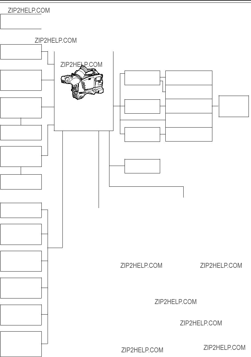
System Configuration
Microphone kit (supplied)
Microphone holder
Lens (Bayonet type) Fujinon/Canon
5w EVF mount adaptor
5w EVF
5w EVF mount adaptor
5w EVF
Rain cover
Soft carrying case
Tripod attachment (supplied)
Extension control unit
Carrying case
Time code input/ output/video input adaptor
AC adaptor
??? 9 ???

Controls and Their Functions
1
4
2
3
Power Supply Section
eBattery holder
The battery pack (option) made by Anton Bauer is mounted onto this holder.
fDC IN (external power input) connector (XLR, 4P)
The
gBREAKER (circuit breaker) button
In order to protect the equipment, the circuit breaker is tripped and the power is automatically turned off when an excessively high level of power flows inside. Upon completion of the inter- nal inspection and adjustments, push this button back in. The power will come back on pro- vided that there is no trouble inside the unit.
hPOWER switch
ON: Set to this position to turn on the unit???s power.
OFF: Set to this position to turn off the unit???s power.
??? 10 ???
Controls and Their Functions
q
p
Accessory Mounting Section
7
9
8
n
o
iHook for mounting shoulder belt
Attach the accessory shoulder belt to this hook.
jLight shoe
Mount the video light, etc. onto this shoe.
kLens mount (bayonet type)
Mount the lens here.
lLens clamping lever
Insert the lens into the lens mount k, and turn the lens mount ring using this lever to clamp the lens.
mLens mount cap
Press up the lens clamping lever l to remove this cap. Keep the cap in place if the lens is not going to be mounted.
nLens cable clamp
This is for clamping the lens cable.
oTripod mount
When the unit is to be secured to a tripod, mount the optional tripod attachment.
pLENS connector
Hook up the lens connecting cable to this connector. Consult with your dealer concerning the lens which you are going to use.
qShoulder pad
Adjust this pad to facilitate operation when carrying the unit on your shoulder. Its position can be brought forward or backward and adjusted by loosening the two set screws.
???11 ???

Controls and Their Functions
s
Audio Function Section (1)
r
rAUDIO LEVEL CH1 (audio channel 1 recording level) control
When the AUDIO SELECT CH1/CH2 switch u is set to MAN, the recording level of audio channel 1 can be adjusted by this control in addition to the AUDIO LEVEL CH1 control t on the side panel.
sMIC IN (microphone input) jack (XLR,
Connect an optional microphone to this jack. The power for the microphone is supplied from this jack.
Audio Function Section (2)
tAUDIO LEVEL CH1/CH2 (audio channel 1/2 recording level) controls
When the AUDIO SELECT CH1/CH2 switch u is set to MAN, the audio level of audio chan- nels 1 and 2 can be adjusted using these controls.
However, the audio CH1 level can also be adjusted using the AUDIO LEVEL CH1 control r on the front panel.
uAUDIO SELECT CH1/CH2 switch (audio channel 1/2 auto/manual level adjustment se- lector) switch
This selects the method used to adjust the audio levels of audio channels 1 and 2. AUTO: For adjusting the levels automatically.
MAN: For adjusting the levels manually.
vAUDIO IN (audio input selector) switch
This selects the input signals to be recorded on audio channels 1 and 2.
FRONT [MIC]: The microphone input signals connected to the MIC IN jack s are recorded.
REAR [MIC]: The microphone input signals connected to the AUDIO IN CH1/CH2 connec- tors w are recorded.
REAR [LINE]: The line input signals connected to the AUDIO IN CH1/CH2 connectors w are recorded.
wAUDIO IN CH1/CH2 (audio input channel 1/2) connectors (XLR, 3P)
An audio component or microphone is connected here.
xAUDIO OUT connector (XLR, 3P)
This is connected to an audio component. The audio channels can be selected on the setting menu.
yDC OUT (DC power output) connector
This is the DC 12 V output connector. A current of approximately 100 mA can be taken out.
??? 12 ???

Controls and Their Functions
z
{
|
t
~
}
Audio Function Section (3)
zALARM (warning tone volume) control
This adjusts the warning tone volume heard from the speaker | or the earphone connected to the PHONES jack ??. When it is set to the lowest position, the warning tone is not audible. However, by making changes to the inside parts, the tone can be made audible even when the control is at its lowest position.
{MONITOR (volume) control
This adjusts the volume of the sound other than the warning
Audio Function Section (4)
|Speaker
During recording, the EE sound can be monitored; during playback, the playback sound can be monitored.
The warning tone is heard through the speaker in synchronization with the flashing or lighting of the warning lamp and warning display.
The speaker sound is automatically muted when an earphone is connected to the PHONES jack ??.
}MONITOR SELECT (audio channel selector) switch
This selects the audio channel whose sound is to be heard through the speaker | or ear- phone.
CH1: The audio channel 1 sound is output.
CH1, 2: The sound produced by mixing the audio channel 1 and 2 sound or the stereo sound is output. However, only the mixed sound is output from the speaker |.
CH2: The audio channel 2 sound is output.
~MONITOR (sound selector) switch
This selects the sound of the earphone when CH1, 2 is selected with the MONITOR SELECT switch }.
ST: The stereo sound of audio channel 1 and 2 is output.
MIX: The mixed sound of audio channel 1 and 2 is output.
??PHONES (earphone) jack
When an earphone (option) is connected to this jack, the sound selected by the MONITOR switch ~ can be heard. The warning tones relating to the unit???s operation or status can also be heard. An earphone enabling a sufficiently high volume of sound to be heard is recom- mended.
When the earphone is connected, speaker | sound is automatically muted.
???13 ???

Controls and Their Functions
?????
???
????? ??????????
?????
Shooting (Recording)/Playback Function Section (1)
Viewfinder
??PEAKING control
This is used to adjust the contours of the images inside the viewfinder to facilitate focusing. It does not affect the camera???s output signals.
??CONTRAST control
This is used to adjust the contrast of the screen inside the viewfinder. It does not affect the camera???s output signals.
??BRIGHT control
This is used to adjust the brightness of the screen inside the viewfinder. It does not affect the camera???s output signals.
??ZEBRA (zebra pattern) switch
This displays the zebra pattern inside the viewfinder. ON: The zebra pattern is displayed.
OFF: The zebra pattern is not displayed.
When the unit is shipped from the factory, the zebra pattern is set in such a way that those parts with an IRE video level from approx. 70% to 85% are displayed. The displaying of parts with a level ranging from 50% to 110% or more or with a certain level can also be set on the setting menu.
??Diopter control knob
This is adjusted in such a way that the images on the viewfinder screen are seen most clear- ly in accordance with the dioptric power of the camera???s operator.
?? Eye cup
?? Viewfinder
??Eyecup
Turn this ring to adjust the position of the eyecup ?? in the
?? Viewfinder stopper screw
??? 14 ???

Controls and Their Functions
?????
?????
?????
?????
?????
?????
Shooting (Recording)/Playback Function Section (2)
??CC/ND FILTER (filter selector) knob
This selects the filter to match the light source which is illuminating the subject.
If the setting of this knob is changed when the menu display mode has been set to ???3??? (de- fault setting), the new setting will appear for about 3 seconds on the setting change message display area of the viewfinder screen.
??The knob and filter settings are listed below.
FILTER
knob setting Description
13200K
25600Ko1/4ND
35600K
45600Ko1/16ND
??Examples of filter settings to match shooting conditions
1Sunrise, sunset, inside a studio
2Outdoors under a clear sky
3Outdoors under a cloudy or rainy sky
4Snow scenes, high mountains, coastlines and other extremely clear and bright scenes
??WHITE BAL (white balance memory selector) switch
PRST: Set to this position when there is no time to adjust the white balance. The white bal- ance value for 3200K is stored in the memory.
A or B: When the AUTO W/B BAL switch ?? is pressed to the AWB side, the white balance is automatically adjusted in accordance with the setting position of the filter knob ??, and the adjustment value is stored in memory A or memory B.
When the FILTER knob and the WHITE BAL switch are set to the same positions as the ones set when the adjustment was made, the adjustment value stored in the memory is called, and the unit is automatically adjusted to the white balance which corresponds to this value.
If the setting of this switch is changed when the menu display mode has been set to ???3??? (de- fault setting), the new setting will appear for about 3 seconds at the WHITE BAL switch dis- play position on the viewfinder screen. (Example: ???W : A???)
???15 ???

Controls and Their Functions
?????
?????
Shooting (Recording)/Playback Function Section (3)
??OUTPUT (output signal selector)/AUTO KNEE switch
This switch selects the video signals which are to be output from the camera unit to the VTR unit, viewfinder and video monitor. The AUTO KNEE function can be used when the images shot by the camera have been selected.
?? OUTPUT/AUTO KNEE switch setting positions
-GAIN (gain selector) switch
This is used to change the video amplifier???s gain in accordance with the lighting conditions during shooting. The gain values corresponding to the L, M and H settings are assigned be- forehand on the setting menu. When the unit is shipped from the factory, these settings are: Lr0 dB, Mr9 dB and Hr18 dB.
If the setting of this switch is changed when the menu display mode has been set to ???3???, the new setting will appear for about 3 seconds at the gain display position on the viewfinder screen. (Example: ???12 dB???)
??AUTO W/B BAL (white balance/black balance automatic adjustment) switch
AWB: Set to this position for automatically adjusting the white balance. When the WHITE BAL switch ?? is now set to ???A or B???, the adjusted value will be stored in memory A or memory B.
ABB: Set to this position for automatically adjusting the black balance. The adjusted value will be stored in the dedicated memory.
??SHUTTER switch
Set this to ON when using the electronic shutter. When it is pressed to the SEL side, the shutter speed and mode displays change in the ranges preset on the setting menu. If the set- ting of this switch is changed when the menu display mode has been set to ???2??? or ???3???, the new settings will appear for about 3 seconds at the shutter display position on the viewfinder screen. (Example: ???:1/250???, ???:1/61.7???)
1)AUTO KNEE function
When the level is adjusted to people, scenes, etc. for shooting against a very bright background, the background will be whited out and the buildings or scenes in the background will become blurred. If the AUTO KNEE function is activated in cases like these, the background can be reproduced in clear detail. This function is especially effective for shooting in the following conditions:
??When shooting people in shade under a clear sky
??When simultaneously shooting people in vehicles or indoor and the outdoor scenery seen through the windows ??When shooting scenes with a high contrast
???16 ???

Controls and Their Functions
????? ?????
?????
??ECU REMOTE (remote control) connector
Connect the
|Note{
The POWER switches on unit and extension control unit must be set to OFF before the re- mote control cable is connected or disconnected.
??
(See page 90 for mounting method.)
The
Furthermore, in case of
??VIDEO OUT connector (BNC)
This outputs the video signals (75?? termination, rated level) to be monitored. During record- ing, EE images can be monitored; during playback, playback images can be monitored. While performing settings on the menu, the setting menu can be superimposed onto the shot images appearing on the monitor screen so that the settings can be checked (in which case, the images appear in black and white).
??CAM OUT (camera output) connector (BNC)
This outputs the composite video signals (75?? termination, rated level). When a video moni- tor is connected, the images shot by the camera can be monitored. Even while the VTR is playing back, the camera???s images are output at all times.
??? 17 ???

Controls and Their Functions
????? ????? ??????????
Shooting (Recording)/Playback Function Section (4)
??VTR START button
When this pressed, recording commences; when it is pressed again, recording stops. This button has the same function as the VTR button on the lens side.
??VTR SAVE/STBY (tape protection) switch
This selects the power supply status while the VTR recording is temporarily stopped (REC PAUSE).
SAVE: This is the tape protection mode. The cylinder is stopped in the
When the switch is set to this position, the VTR SAVE lamp inside the viewfinder lights.
STBY: Recording commences immediately when the VTR START button is pressed.
??MODE CHECK button
While this button is kept depressed, the camera???s setting status is displayed in the viewfinder. It does not affect the camera???s output signals. This button can also be used for fine adjust- ment at the setting menu during synchro scan mode.
??SUPER IRIS button
This is used when backlight compensation is to be provided. When it is pressed, the switch settings are displayed inside the viewfinder for 3 seconds. When it is pressed again, back- light compensation is released.
Whether the super gain (30 dB) mode or the super iris (backlight compensation) mode is to apply can be selected on the setting menu. This button can also be used for fine adjustment during synchro scan mode.
Super gain: When 30 dB is allotted to the SUPER IRIS button, DTL and other menu settings cannot be performed for this 30 dB.
??? 18 ???
Controls and Their Functions
???????????????
?????
??EJECT (cassette eject) button
Press this to insert or eject the cassette.
??REW (rewind) button
Press this to rewind the tape. Its lamp lights during rewinding.
If this button is pressed during playback, the playback images are rewound at approximately quadruple speed while the button is held down.
??FF (fast forward) button
Press this to fast forward the tape. Its lamp lights during fast forwarding.
If this button is pressed during playback, the playback images are fast forwarded at approxi- mately quadruple speed while the button is held down.
??PLAY (playback) button
Press this to view the playback images on the viewfinder screen or color video monitor. Its lamp lights during playback.
If this button is pressed again during playback, playback is paused and the lamp goes off. After playback has been paused for 2 minutes, the unit automatically switches to stop status (STOP).
??STOP button
Press this to stop the tape travel.
??Emergency screw (Inside the rubber cap)
Refer to page 118 ???Emergency eject???.
??? 19 ???

Controls and Their Functions
?????
?????
?????
??(??) ??(??)
??(??)
????? ?????
Menu Operation Section
??MENU SET/OFF switch
This displays the setting menu on the viewfinder screen.
SET: The page on which the previous setting menu operations were completed appears on the viewfinder screen. (When the menu is used for the first time, the first of the pages which can be displayed appears.)
OFF: The setting menu is not displayed on the viewfinder screen.
??SHIFT/ITEM button
Each time this button is pressed, the cursor moves on the setting menu page now displayed. Use it when selecting items.
|Note{
This switch functions differently depending on the operation item. Check the function by oper- ating the menu item by item.
??UP button
This is used to increment the setting of the item selected on the setting menu by 1 level each time it is pressed or to switch the setting between ON and OFF.
??DOWN button
This is used to decrement the setting of the item selected on the setting menu by 1 level each time it is pressed or to switch the setting between ON and OFF.
??PAGE button
This is used to select the setting menu page.
Time
??GENLOCK IN connector (BNC)
The reference signal is supplied to this connector for genlocking with the camera section.
??? 20 ???
Controls and Their Functions
?????
Time
??HOLD button
The time data appearing on the counter display at the instant when this button is pressed is held. (The time code generator will still continue to run.) When the button is pressed again, the hold status is released. Use the button to ascertain the time at which a particular scene was shot, for example.
??RESET button
This resets the time data on the counter display to ???00:00:00:00???. When the TCG switch ?? is set to SET and this button is pressed, the time code or user???s bit can be reset to ???00:00:00:00??? or ???00 00 00 00???.
??DISPLAY switch
The time code, CTL or user???s bit is made to appear on the counter display depending on the setting positions of this switch and the TCG switch ??.
UB: The user???s bit is displayed.
TC: The time code is displayed.
CTL: CTL is displayed.
??UP button, DOWN button
When setting the time code or user???s bit, these buttons increment or decrement by 1 the fig- ure of the digit made to flash by the SHIFT/ITEM button ??.
??SHIFT/ITEM (digit advance) button
When setting the time code or user???s bit, this button is used to cause the digit which is to be set to flash.
??? 21 ???

Controls and Their Functions
?????
?????
?????
?????
?????
??TCG (time code selector) switch
This is used to set the running mode of the internal time code generator.
Set to this position when aligning the time code with the actual time or locking the time code to an external source.
SET: This position is used for setting the time code or user???s bit.
Warning/Status Display Section
??Tally lamp
This is activated when the TALLY switch ?? is at HIGH or LOW, and it lights during recording by the VTR section. It flashes in the same way as the REC lamp inside the viewfinder to warn the operator. The brightness when lighted can be selected using the TALLY switch (HIGH or LOW).
??TALLY switch
This controls the tally lamp ??.
HIGH: The tally lamp is made brighter.
OFF: The tally lamp is extinguished.
LOW: The tally lamp is made darker.
??Back tally lamp
This functions in the same way as the tally lamp ?? when the back tally switch ?? is set to ON.
??Back tally switch
This controls the back tally lamp ??. ON: The back tally lamp operates.
OFF: The back tally lamp does not operate.
??WARNING lamp
This flashes or lights when trouble occurs in the VTR section.
??LIGHT switch
ON: This illuminates the display window ??.
OFF: This extinguishes the display window illumination.
??Display window
The warnings related to the VTR section, remaining battery level, sound level, time data, etc. are displayed in this window.
???22 ???

Power Supply
Power can be supplied to the unit using a battery pack or AC power supply.
Using a battery pack
A Panasonic, B Anton Bauer or C Sony batteries can be used for the battery pack.
Before using a battery pack, be sure to charge it completely using a battery charger.
??See the Handling Instructions for the battery pack and battery charger for a detailed explana- tion of charging methods.
Using an Anton Bauer Battery Pack
1 Mount the battery pack.
Insert the battery pack in the direction of the arrow and then slide it into place.
Power Supply Output Connector
Control Switch
2 When detaching the battery, hold down the detachment lever of the battery holder and slide the battery pack in the direction of the arrow.
Lever
Pack
|Note{
The
Automatic detection can be performed for intelligent batteries with a remaining battery level of 10% or more. At this time, the remaining battery level is displayed numerically (percent- age display) inside the viewfinder. If the power is turned on with a remaining battery level of 10% or less, the voltage is displayed. Also, after intelligent battery detection, the remaining battery level display indicates the level for the intelligent battery even if power is supplied from an external source.
??? 23 ???

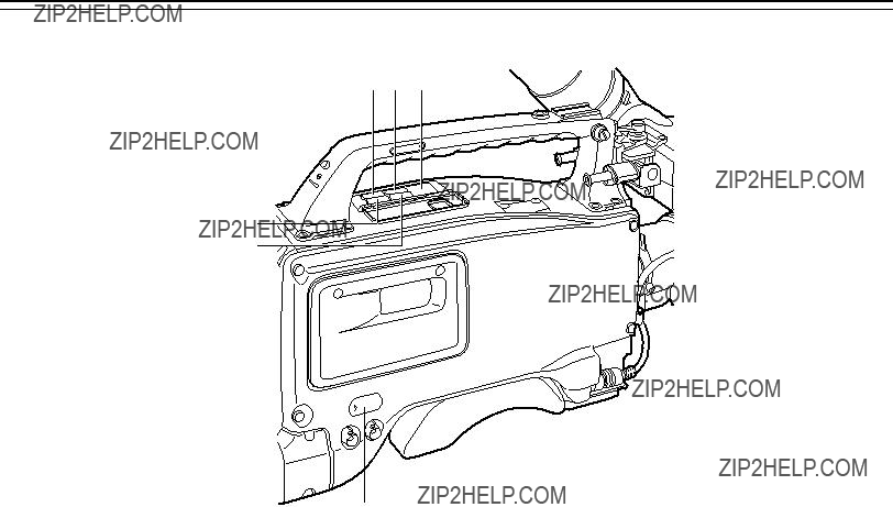
Power Supply
Using the Panasonic
1 Detach the battery mounts.
2 Connect the unit???s connectors with the connectors of the
3 Mount the
Open the battery case cover and lift up the rubber cap to expose the screw holes. Tighten the screws with a screwdriver and mount the case to the unit. Be sure to tighten the screws completely.
|Notes{
??Do not pull strongly on the rubber cap.
??Take care not to catch the connection cord between the battery case and the main unit.
??? 24 ???

Power Supply
4 Connect the battery pack plug to the connector inside the case and insert the battery pack.
|Note{
The unit???s power must be set to OFF before the plug is inserted or removed.
??? 25 ???

Power Supply
Using a Sony Battery Pack
1 Remove the battery mounts. See page 24.
2 Mount the accessory battery mounting connector.
3 Mount the Sony battery holder.
Mount the battery case with the cover detached first, and then mount the detached cover as shown in the figure.
A Tighten the mounting screws.
B Tighten the power supply contact screws.
C Insert the top of the detached cover in the direction of the arrow.
DAlign the hole at the bottom (metal part) of the cover with the hole at the bottom of the case and mount the cover to the battery mounting connector with the screw of the bat- tery holder.
A
C
 D
D
B
|Note{
Take care when attaching the battery holder that the wires are not pinched.
??? 26 ???

Power Supply
Using the Sony
1 Mount the accessory battery mounting connector. (See the preceding page.)
2 Mount the
B Tichten the power supply contact screws.
C Insert the top of the detached cover in the direction of the arrow.
DAlign the hole at the bottom (metal part) of the cover with the bottom of the case and mount the cover to the battery mounting connector with the screw.
|Notes{
??The unit???s power must be set to OFF before the plug is inserted or removed. ??Take care when attaching the battery case that the wires are not pinched.
??? 27 ???

Power Supply
Using an AC Power Supply (When using the
1 Connect the unit???s EXT DC IN socket with the DC OUT connector of the
DC IN Connector
2
3
Set the AC adaptor???s power to ON.
Set the unit???s power switch to ON.
|Notes{
??When using an external power supply other than the
??When both a battery pack and AC adaptor are connected, power is supplied from the AC adaptor.
??When using an AC adaptor, the AC adaptor???s power must be set to ON before the unit???s POW- ER switch is set to ON. If this sequence is reversed, the AC adaptor???s output voltage will rise slowly and may cause the unit to malfunction.
4
1 2 3
??? 28 ???

Mounting the Lens
1 Raise the lens clamping lever and remove the mount cap.
Lens Clamping Lever
Mount Cap
2 Align the indentation at the top center of the lens mount with the center mark of the lens and mount the lens.
Mark
3
4
Lower the lens clamping lever and clamp the lens.
Press the cable into the cable clamp and connect it to the LENS connector.
LENS Connector
??See the Handling Instructions provided with the lens for lens handling.
|Note{
The lens and camera adjustments listed below may be necessary depending on the lens to be mounted.
1.Lens flanging adjustment
2.Lens auto iris adjustment
3.Lens white shading adjustment (with this unit)
??? 29 ???
Adjusting the Lens Flange
When images are not clearly focused at both the telephoto and
Once adjusted, the flange back does not need to be readjusted as long as the lens is not changed.
Adjustment method
Check the position of each part of the lens which must be operated in order to adjust the flange back with the lens Handling Instructions.
Approx. 10 ft
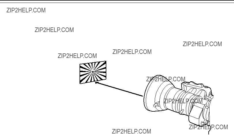
Adjusting the Flange Back
1
2 Open the iris. Position the flange back adjustment chart about 10 ft from the lens and illumi- nate it so that an appropriate image output level is obtained.
If the image level is too high, use the CC/ND filters or the shutter.
3
4
5 Shoot the flange back adjustment chart and turn the distance ring to bring the chart into focus.
6
7 Turn the Ff ring to bring the chart into focus.
At this time, take care not to move the distance ring.
8 Repeat this operation four to seven times until the lens is in focus at both the telephoto and
9 Firmly tighten the Ff ring clamping screw.
??Refer to the Operating Instructions of the lens.
??? 30 ???
Adjusting the White Shading
The
The
(Vertical coloring refers to the condition where the top of the screen is green and the bottom is magenta or where these colors are reversed when a white paper is shot for the entire screen.)
White shading adjustment procedure
1 Mount a lens to the camera.
Be sure to also connect the lens cable.
2 Set the electronic shutter to OFF and the gain to L (0 dB).
GAIN: L (0 dB)
3
4 Set the MENU SET/OFF switch from OFF to SET while holding down the SHIFT/ITEM and UP buttons to open the menu.
Press the PAGE button until the VF OPERATION page appears.
Set ZEBRA1 DETECT to 70, ZEBRA2 DETECT to 85 and ZEBRA2 to SPOT. (Initial set- ting mode)
Return the MENU SET/OFF switch from SET to OFF to close the menu. Set the viewfinder???s ZEBRA switch to ON.
MENU
PAGE
SHIFT/ITEMoUP
5 Shoot an evenly white paper.
Flickering occurs easily when fluorescent or mercury lamps, etc. are used for lighting. Therefore, use a light source which does no produce flickering such as sunlight or halo- gen lamps, etc.
6 Set the lens iris to manual and adjust the iris so that the ZEBRA pattern covers the entire screen. If the light strikes the subject in an uneven manner, the ZEBRA pattern will not cover a part of the screen. Therefore, adjust the position of the light source, etc. as neces- sary.
Check that the lens iris is between F4 to F11. If the lens iris is not within this range, adjust the position of the light source, etc.
(Be sure to set the electronic shutter to OFF.)
??? 31 ???
Adjusting the White Shading
7 Set the WHITE BAL selector switch to A or B execute AWB. Next, execute ABB and then execute AWB again.
WHITE BAL: A or B
8
9 Set the MENU switch from OFF to SET while holding down the SHIFT/ITEM and UP but- tons to open the menu.
Press the PAGE button until the AUTO SHADING page appears.
Press the SHIFT/ITEM button to move the arrow on the left to the WHITE position and then press the UP or DOWN button.
ACTIVE appears on the viewfinder to indicate that white shading automatic adjustment is operating.
Adjustment is completed when the ACTIVE display disappears. Return the MENU switch from SET to OFF to close the menu.
MENU
PAGE
SHIFT/ITEMoUP
10 When the lens to be used has an extender, insert an extender and repeat steps 6 to 9.
This completes white shading adjustment.
The adjustment value is stored in the
|Notes{
1.The white shading can be adjusted for general lenses using the above method. However, this method may not apply for extremely special lenses.
2.When using a
3.Vertical coloring may occur near the open position of the lens iris even after performing the above adjustments. However, this is characteristic of the optical system of the lens, and does not indicate a malfunction.
???32 ???

Adjusting the Viewfinder
Adjusting the Position
1 Loosen the viewfinder
Viewfinder
KOOL
Lever
2 Adjust the position of the viewfinder in the
KOOL
3 Tighten the viewfinder
KOOL
??? 33 ???

Adjusting the Viewfinder
Adjusting the Diopter and Screen
Adjusting the diopter
1 Set the POWER switch to ON. A picture will appear in the viewfinder.
2 Turn the diopter adjustment ring to adjust the diopter so that the viewfinder picture can be clearly seen.
Diopter Adjustment Ring
- 3
- 2
- 1
0
+1 +2 +3
Adjusting the screen
Adjust the condition of the viewfinder screen.
Brightness: Adjust the BRIGHT control
Contrast: Adjust the CONTRAST control
Contour: Adjust the PEAKING control
BRIGHT Control
CONTRAST Control
PEAKING Control
1
2
Set the POWER switch to ON.
Set the OUTPUT switch to CAM.
3 Turn the viewfinder BRIGHT and CONTRAST controls to adjust the picture brightness and contrast. Turning the PEAKING control makes the picture appear softer or sharper. A sharp picture facilitates focusing the lens.
Adjusting the Eyecup Position
Turn the eyecup
Eyecup
??? 34 ???

Adjusting the Viewfinder
Detaching the Eyecup
Detaching the eyecup allows the entire screen to be seen clearly even when shooting with your eye removed from the viewfinder. This also facilitates the removal of dust which has adhered to the CRT screen and mirror.
|Note{
Absolutely do not wipe the mirror surface as it has been specially treated. Dust which has ad- hered to the mirror should be blown away with a blower, etc.
1 Press the lock button.
2
Lock Ring 
1
3 Detach the eyecup.
Remounting the eyecup
1.Line up the alignment marks on the lock ring and the viewfinder barrel, and then insert the eyepiece.
2.Turn the eyepiece as far as possible in the clockwise direction. The lock button latches with a clicking sound, and remounting is completed.
??? 35 ???

Adjusting the Viewfinder
Detaching the Viewfinder
1 Check that the POWER switch is set to OFF.
2 Disconnect the plug from the viewfinder cable connector.
|Note{
Use both hands to detach the viewfinder. The viewfinder may not detach smoothly with one hand, resulting in damage to the viewfinder.
3 Loosen the viewfinder stopper screw and detach the viewfinder by pulling it straight up.
Stopper Screw
Pull straight up.
Hook your fingers here.
Mounting the Viewfinder
1
2
Press down the viewfinder.
Tighten the viewfinder stopper screw firmly.
3 Connect the plug to the viewfinder connector and secure the viewfinder cable with the clamp.
|Note{
Insert the plug firmly when connecting it to the viewfinder connector.
Stopper Screw
??? 36 ???

Audio Input Preparations
Using the Microphone Mounted to the Main Unit
Using the microphone kit (standard accessory) or the
??See the Handling Instructions for the microphone holder.
Using the Microphone Kit (standard accessory) Microphone Mounted to the Main Unit
1 Mount the microphone.
2 Connect the microphone connecting cable to the unit???s MIC IN jack.
MIC IN Connector
??? 37 ???

Audio Input Preparations
Mounting the
1 Remove the microphone holder mounting screws.
2 Mount the
Mount the microphone
adaptor using the
accessory screws.
3
4
Mount the microphone to the microphone holder and tighten the screws.
Connect the microphone connecting cable to the MIC IN jack.
To the MIC IN Connector
5 Set the AUDIO IN switch to FRONT [MIC] in accordance with the audio channel to be re- corded.
??? 38 ???

Audio Input Preparations
Using the Microphone not Mounted to the Main Unit
To the MIC IN Connector
AUDIO IN switch: Set the AUDIO IN switch for
the audio channel you wish to
record to FRONT [MIC].
|Note{
When extending the microphone, use a cable which supports the phantom power supply type of microphone.
Using the Microphone not Mounted to the Main Unit
 Up to two external microphones can be connected to the AUDIO IN CH1/CH2 Connectors.
Phantom power supply type microphones can also be supported by a menu setting.
AUDIO IN Switch: Set the AUDIO IN Switches of the channels to which microphones are connected to REAR [MIC].
??? 39 ???

Audio Input Preparations
Mounting a Wireless Microphone
When using the Panasonic wireless microphone system, mount the
To the AUDIO OUT Connector
Wireless Receiver
??See the Handling Instructions for the
Connecting an Audio Component
When using an audio component as the line input signal source, connect the audio component to the unit???s AUDIO IN CH1/CH2 connectors.
AUDIO IN Switch:
Set the AUDIO IN Switch of the channel to which the audio signal source is connected to REAR [LINE].
Audio Equipment
Connect to the AUDIO IN
CH1/CH2 Connectors.
??? 40 ???
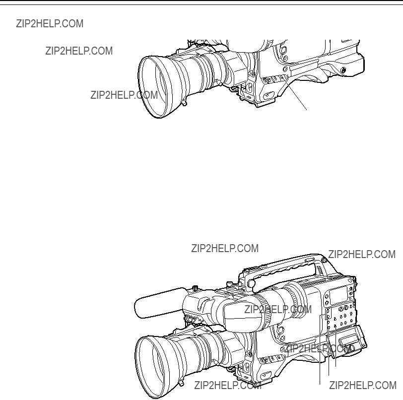
Mounting the Unit to a Tripod
When mounting the unit to a tripod, use a supplied tripod attachment.
1 Mount the tripod attachment to the tripod.
Select the attachment hole in consideration of the unit???s and tripod attachment???s center of gravity. In addition, check that the diameter of the selected hole matches the diameter of the universal head???s camera mounting screw.
Tripod Attachment
2 Mount the camera to the tripod attachment.
Slide the unit forward along the grooves until a clicking sound is heard.
When detaching the tripod attachment
Hold down the red lever and move the black lever in the direction of the arrow.
|Note{
When the tripod attachment pin does not return to its original position after the camera has been detached, hold down the red lever and move the black lever in the direction of the arrow again to return the pin to its original position.
Care should be taken as the camera cannot be mounted if the pin remains in the center.
??? 41 ???

Adjusting the Shoulder Pad Position
The shoulder pad can be slid up to 2/5?? in the
1
2
3
Loosen the two screws.
Slide the pad in the
Tighten the screws to clamp the pad.
Screws
Shoulder Pad
Bottom
??? 42 ???

Attaching the Rain Cover
Attach the rain cover as shown in the figure below.
Tighten the Cord.
??? 43 ???

Connecting the
Connecting the
When the
The handling instructions included with the
When the
ECU Connector
|Notes{
??The POWER switches of the unit and
??All adjustments and settings made using the switches and controls other than the menu setting section of the
(Menu contents set with the menu setting section are saved.)
|Note{
The functions of the
(If the menu settings are changed while the
Note that the
??The Synchro scan and Super V modes cannot be used while the
??The lens iris (IRIS) control of the
??? 44 ???

Warning/Status Displays in the Viewfinder and Display Window
Displaying the Setting Menu Inside the Viewfinder
When the MENU SET/OFF switch is set to SET, the setting menu appears on the viewfinder screen. The setting menu is displayed in page units. The following table lists all pages contained in the setting menu as well as an outline of the functions for each page.
The setting menu configuration can be changed according to the purpose.
Setting Menu Configuration
See the corresponding pages for a detailed description of each page???s functions.
|Note{
When connecting the
??? 45 ???

Warning/Status Displays in the Viewfinder and Display Window
Changing the setting menu configuration
The setting menu can be configured by selecting only the pages necessary for the application. Pages are selected using the MENU SELECT page of the engineer menu mode.
When using the engineer menu, switch the unit to engineer mode as described below. The unit is switched to user mode by setting the MENU SET/OFF switch to ???SET???.
The unit is switched to engineer mode by holding down the SHIFT/ITEM and UP buttons simul- taneously and setting the MENU SET/OFF switch to SET.
The user and engineer modes differ as follows.
User mode: Only the selected pages the setting menu can be used. The data set on each page is written to the
Engineer mode: All pages contained in the setting menu can be used. In addition, the data set at each page is written to the
After completing the adjustments and settings with engineer mode, configuring a menu consist- ing only of frequently used pages allows the necessary pages to be called quickly.
??? 46 ???

Warning/Status Displays in the Viewfinder and Display Window
Basic Setting Menu Operations
The setting menu is operated using the MENU SET/OFF switch and the SHIFT/ITEM, UP, DOWN and PAGE buttons.
SHIFT/ITEM Button
UP Button
SHIFT
 ST
ST
 MIX
MIX
CH1 AUDIOLEVEL CH2
MENU SET/OFF Switch
Displaying the setting menu
1 Set the MENU SET/OFF switch to SET.
The status displays at the top and bottom of the viewfinder screen disappear, and the page on which the previous setting menu operations were completed appears.
When the menu is used for the first time, the first of the selected pages appears.
- MARKER -
?????CENTER MARK : ON
SAFETY ZONE : 1
Changing the page
1 Press the PAGE button.
The menu page changes each time the PAGE button is pressed.
- ! L ED -
????????EGA I N ( 0 d B ) ?????? . GA I N ( - 3 d B )
ESHUT TER ??? ??? ??? ??? ???
. WH I TE PRESET
EEXTENDER
. F I L TER
. SUPER V
The page can also be changed using the UP and DOWN buttons as follows.
??PAGE??UP: The menu page is incremented continuously while the UP and PAGE but- tons are held down.
??PAGE??DOWN: The menu page is decremented continuously while the DOWN and PAGE buttons are held down.
??? 47 ???

Warning/Status Displays in the Viewfinder and Display Window
Selecting the desired item
1 Press the SHIFT/ITEM button.
Each time this button is pressed, the cursor (arrow) which indicates the selected item moves to the next item.
- MARKER -
Cursor
?????CENTER MARK : ON
Movement order ??? SAFETY ZONE : 1
The item can also be selected using the UP and DOWN buttons as follows.
Changing the settings
Press the UP button to increase the setting. ??The setting is incremented by 1 level each time
the UP button is pressed.
Press the DOWN button to decrease the setting. ??The setting is decremented by 1 level each time
the DOWN button is pressed.
Changing the ON/OFF selection
SHIFT
The setting switches to ON or OFF each time the UP (or DOWN) button is pressed.
Returning to the default settings
The unit can be returned to the default settings (the settings when shipped from the factory or the engineer mode settings) by pressing the UP (or DOWN) button at the DATA RESET page of engineer modeF.
However, care should be taken as the flare and shading adjustment values cannot be returned to the default settings.
Quitting the menu
Set the MENU SET/OFF switch to OFF.
??The setting menu disappears from the viewfinder screen and the displays indicating the unit???s current status appear at the top and bottom of the viewfinder screen.
FEngineer mode
The menu for this mode is opened by holding down the SHIFT/ITEM and UP buttons simulta- neously and then setting the MENU SET/OFF switch to the ???SET??? position.
??? 48 ???

Lamp Displays Inside the Viewfinder
The viewfinder displays are as follows.
REC 1
! BATT
VTR SAVE
3 2 4
1.REC (recording) lamp
This lamp lights (red) during recording, and flashes when warnings are issued. ??See ???Warning System??? (page 116) for a detailed description.
2.BATT (battery) lamp
When the battery voltage has dropped, this lamp begins flashing several minutes before the unit can no longer be operated, and lights when the unit can no longer be operated.
To prevent operation from being interrupted, exchange the battery quickly before the battery runs out.
3.! (irregular operation status warning) lamp
This lamp lights when the unit enters irregular operation status for any of the items set to ON at the ! LED page of the setting menu. Applicable items are as follows.
??See ???Setting the ! Lamp Display??? (next page) for selecting ! lamp display items.
4.VTR SAVE (VTR power saving) lamp
This lamp lights when the VTR SAVE/STBY switch is set to SAVE. It is not lighted during recording.
|Note{
Regardless of the VTR SAVE/STBY switch, the unit automatically enters the SAVE state and the lamp lights either after two minutes when in the stopped state, or after the length of time set for the pause timer (the pause time) when in the paused state.
??? 49 ???

Lamp Displays Inside the Viewfinder
Setting the ! Lamp Display
Items subject to ! lamp display are selected at the ! LED page of the setting menu. (When shipped from the factory, the unit is set so that the ! LED page is not displayed.) To operate the ! LED page, switch the unit to engineer mode or select the ! LED page at the MENU SELECT page.
??See ???Setting Menu Configuration??? (page 45) for engineer mode and selection of displayed pages.
1 Set the MENU SET/OFF switch to SET.
The setting status displays disappear from the viewfinder screen, and the page on which the previous setting menu operations were completed appears. (When the menu is used for the first time, the first page appears.)
2 Press the PAGE button until the ! LED page shown below appears. (This operation can also be performed using the PAGEoUP/DOWN buttons.)
??EGAIN (0 dB): This selects whether or not the ! lamp lights when the gain is set to any value other than 0 dB.
.GAIN (??3 dB): This selects whether or not the ! lamp lights when the gain is set to any value other than p3 dB.
ESHUTTER: This selects whether or not the ! lamp lights when the SHUTTER switch is set to ON.
.WHITE PRESET: This selects whether or not the ! lamp lights when the white balance memory channel is PRST.
EEXTENDER: This selects whether or not the ! lamp lights when the lens is in EX- TENDER mode.
.FILTER:This selects whether or not the ! lamp lights when the filter is set to any value other than 3200K.
.SUPER V:This selects whether or not the ! lamp lights when SUPER V is set to ON.
3
4 Press the UP and DOWN buttons to choose ! lamp lighted/not lighted for the selected item. To select ON: Press the UP button. An asterix (E) appears to the left of the item name. To select OFF: Press the DOWN button. A period (.) appears to the left of the item name.
Repeat steps 3 and 4 to continue making ON/OFF settings for other items.
5 When menu operations have been completed, set the MENU SET/OFF switch to OFF.
The setting menu disappears from the viewfinder screen and the displays indicating the unit???s current status appear at the top and bottom of the viewfinder screen.
??? 50 ???
Status Displays Inside the Viewfinder Screen
In addition to images, messages indicating the unit???s settings and operating status appear on the viewfinder screen. The center marker and safety zone marker, etc. are also displayed.
When the MENU SET/OFF switch is set to OFF, items set to SET at the VF DISPLAY page of the setting menu and using related switches appear at the top and bottom of the screen. Messages informing of the setting contents or of the adjustment course or results can also be displayed for approximately 3 seconds when settings are changed, during the course of adjust- ments, or after adjustments have been completed.
??See ???Selecting Display Items??? (page 54) for selecting display items, ???Display Mode and Setting Change Message??? (page 55) for the setting change message, and ???Setting the Marker Displays??? (page 56) for the marker displays.
The display positions of all items which can be displayed are shown in the figure below.
1.Extender display
2.Shutter speed/mode display
3.Remaining tape length display
4.Remaining battery level display
5.Filter display
6.White balance memory display
7.Gain value display
8.Audio level display
9.Iris value display
10.Warning display
11.Safety zone marker
12.Center marker
13.Super iris ON display
14.TCG (Time Code Generator) display
??? 51 ???

Status Displays Inside the Viewfinder Screen
1 Extender display
This is displayed when the lens extender is being used.
2 Shutter speed/mode display
This displays the shutter speed or shutter mode setting.
OFF:The shutter is not used.
1/100, 1/120, 1/250, 1/500, 1/1000, 1/2000:
Shutter speeds (seconds) during standard mode.
Synchro scan mode is selected.
SUPER V:High vertical resolution mode is selected.
3 Remaining tape length display
This indicates the remaining tape length (minutes) for the VTR during recording.
5
6
7
When an Anton Bauer Digital Magnum Series battery is used to supply power to the unit, the remaining battery level is displayed numerically (%).
Filter display
This displays the type of filter selected.
White balance memory display
This displays the selected white balance automatic adjustment memory.
A:The WHITE BAL switch is set to A.
B:The WHITE BAL switch is set to B.
P: The WHITE BAL switch is set to PRST.
Gain value display
This displays the image amplifier gain setting (dB) set by the GAIN switch.
|Note{
When using an Anton Bauer Digital Magnum Series battery, the remaining battery level display continues to display the level for the Anton Bauer battery even if power supply is switched to an external power source near the end of the battery???s power. However, note that the unit operates according to the external power source.
??? 52 ???

Status Displays Inside the Viewfinder Screen
8 Audio level display
This displays the audio CH1 level.
During sine wave input, the audio level display corresponds roughly to the VTR level
meter display as follows.
Audio Channel 1 Level Display
VTR Level Meter
9
10
11
Iris value display
This displays the approximate iris setting (F number).
Warning display
This displays the black balance, white balance, auto knee function, super iris, super high gain and other warning displays.
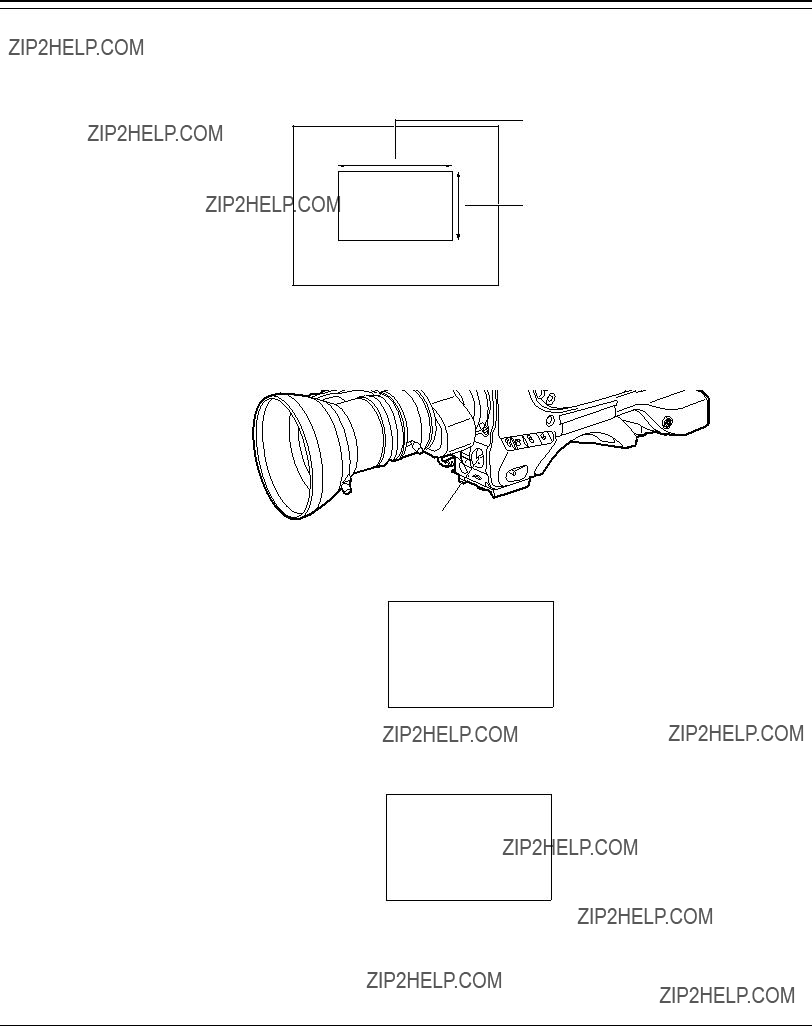
Safety zone marker
This indicates the 80% or 90% (setting when shipped from the factory) range for the view- finder screen area. The screen area percentage is selected at the MARKER page of the setting menu.
??See ???Setting the Marker Displays??? (page 56) for a detailed description.
12 Center marker
13
14
This indicates the center of the viewfinder screen. This marker is displayed when set to ON at the MARKER page of the setting menu.
Super iris ON display
This indicates that the super iris is ON.
TCG display
This displays the time code generator value.
1) Iris value display
The iris value is displayed when using a lens with the iris value display function.
??? 53 ???

Status Displays Inside the Viewfinder Screen
Selecting Display Items
The items to be displayed on the viewfinder screen can be selected by switching the display ON/OFF setting independently for each item at the VF DISPLAY page. The items which can be selected are as follows.
??Display mode (See ???Display Mode and Setting Change/Adjustment Course Message???.) ??Extender display
??Shutter speed/mode display ??Remaining tape length display ??Remaining battery level display ??Filter display
??White balance memory display ??Gain value display
??Level meter display
??Iris value/super iris ON status display ??Camera ID display
??The camera ID is displayed when recording the color bar according to the OUTPUT/AUTO KNEE switch setting. See ???Setting the Camera ID??? (page 57) for a detailed description.
Select the items to be displayed on the viewfinder screen.
1 Set the MENU SET/OFF switch to SET.
The page on which the previous setting menu operations were completed appears on the viewfinder screen. (When the menu is used for the first time, the first page appears.)
2 Press the PAGE button until the VF DISPLAY page shown below appears. (This operation can also be performed using the PAGEoUP/DOWN function.)
3
4 Press the UP and DOWN buttons to choose whether to display (ON) or not display (OFF) the selected item on the viewfinder screen.
The setting switches to ON or OFF each time the UP (or DOWN) button is pressed. Repeat steps 3 and 4 when setting display ON/OFF for other items.
5 When menu operations have been completed, set the MENU SET/OFF switch to OFF.
The setting menu disappears from the viewfinder screen and the displays indicating the set- tings of the selected items appear.
??? 54 ???

Status Displays Inside the Viewfinder Screen
Display Mode and Setting Change Message
Messages informing of the contents of changed settings and adjustment results can be limited to part of the displayed items or not displayed for all items.
The conditions under which messages are displayed and the corresponding display modes are shown in the table below.
Setting change/adjustment results messages and display modes
F) The message is displayed for approximately 3 seconds immediately after the power for the unit is turned on.
??? 55 ???

Status Displays Inside the Viewfinder Screen
Changing the Display Mode
The display mode setting appears on the VF DISPLAY page of the setting menu.
1 Perform the operations in steps 1 to 3 of ???Selecting Display Items??? (page 54) to display the VF DISPLAY page of the setting menu on the viewfinder screen and align the cursor with the DISP MODE item.
2
3
Press the UP or DOWN button to select the desired display mode.
When menu operations have been completed, set the MENU SET/OFF switch to OFF.
Setting the Marker Displays
Display ON/OFF switching for the center and safety zone markers and selection of 80% or 90% of the screen area as the safety marker range are performed at the MARKER page of the setting menu.
1 Set the MENU SET/OFF switch to SET.
The page on which the previous setting menu operations were completed appears on the viewfinder screen. (When the menu is used for the first time, the first page appears.)
2 Press the PAGE button until the MARKER page shown below appears.
(This operation can also be performed using the PAGEoUP/DOWN function.)
- MARKER -
?????CENTER MARK : ON
SAFETY ZONE : 1
3
4
5 When menu operations have been completed, set the MENU SET/OFF switch to OFF.
The setting menu disappears from the viewfinder screen and the displays indicating the unit???s current status appear at the top and bottom of the viewfinder screen.
??? 56 ???

Status Displays Inside the Viewfinder Screen
Setting the Camera ID
The camera ID can be set at the CAMERA ID page of the setting menu.
A camera ID of up to ten characters including English letters, symbols and spaces can be used. The camera ID is recorded when the OUTPUT/AUTO KNEE switch is set to BARS and the color bar signal is being recorded. It is also displayed on the viewfinder screen.
|Note{
When the setting menu is displayed, the camera ID is not displayed even if the color bar signal is output.
1 Set the MENU SET/OFF switch to SET.
The page on which the previous setting menu operations were completed appears on the viewfinder screen. (When the menu is used for the first time, the first page appears.)
2 Press the PAGE button until the CAMERA ID page shown below appears. (This operation can also be performed using the PAGEoUP/DOWN function.)
- CAMERA I D -
??? ???
I D : E E E E E E E E E E
:The cursor is moved to the right (max. 10 spaces) by the SHIFT/ITEM button.
:English letters, symbols and space are switched by the UP and DOWN buttons.
Camera ID
(???F??? indicates a space. This indication is only used at this menu page.)
3 Press the UP (or DOWN) button until the desired character appears.
Each time the UP button is pressed, the character display changes in the order of English letters (A to Z)??numbers (0 to 9)??symbols [space, {, |, ), (, ???, ???,
4
5 When menu operations have been completed, set the MENU SET/OFF switch to OFF.
The setting menu disappears from the viewfinder screen and the displays indicating the unit???s current status appear at the top and bottom of the viewfinder screen.
??? 57 ???

Displays
Remaining Battery Level and Audio Level Displays
Remaining tape length
When the amount remaining on the tape is more than
30 minutes long, all seven segments up to the ???F??? posi- tion appear lighted.
When it is less than 30 min- utes long, one segment will go off for every
Remaining battery level
VTR Section
Lights  DF SLAVE TCG HOLD
DF
SLAVE
TCG

 RF SERVO HUMID SLACK
Warning display
RF: Lights when video head clogging occurs.
SERVO: Lights when the servo is out of order.
HUMID: Lights when condensation occurs on the head drum.
SLACK: Lights when tape
EMPHASIS
0
10
20
30
40
CH1 dB CH2
??See ???Warning System??? (page 116) for a detailed description.
??? 58 ???

Displays
Time
These lamps light to indicate the time code, CTL and real time displays.
DF: This lamp lights during drop frame mode
SLAVE: This lamp lights when the time code is locked to an external source.
HOLD: This lamp lights when the time code generator is held (when the HOLD button is pressed).
Time counter display: This displays the time code, CTL, user bit and real time.
??See below for the relationship between displayed items and switch settings.
Relationship between the TCG and DISPLAY switch setting positions and the time counter display
The item displayed in the time counter display is determined by the TCG switch and DISPLAY switch settings.
Time
??? 59 ???

Adjusting the Time and Date
Adjustment and setup using the setting menu
1.Hold down the SHIFT/ITEM and UP buttons and set the MENU SET/OFF switch to SET. The unit switches to ENG mode.
The page on which the previous setting menu operations were completed appears on the viewfinder screen.
(When the menu is used for the first time, the first page appears.)
2.Press the PAGE button until the TIME/DATE page shown below appears. (This operation can also be performed using the PAGEoUP/DOWN function.)
3.Press the SHIFT/ITEM button to select the item to be changed.
4.Press the UP (or DOWN) button to change the setting value.
The number is incremented by o1 each time the UP button is pressed and decremented by p1 each time the DOWN button is pressed.
5.When the settings have been completed, press the SHIFT/ITEM button to select TIME/DATE SET and then press the UP (or DOWN) button. The time starts from when the button is pressed.
?????T I ME / DATE SE T
6.When menu operations have been completed, set the MENU SET/OFF switch to OFF.
The setting menu disappears from the viewfinder screen and the displays indicating the unit???s current status appear at the top and bottom of the viewfinder screen.
|Note{
The seconds cannot be set and always start from 0 seconds.
??? 60 ???
Adjustments and Setup During Recording
Adjustments and Setup Using the Setting Menu
Adjustments and setup operations during recording are performed at the setting menu.
Setting menu operations are basically performed according to the procedures described on page 47.
However, these procedures vary slightly according to the item.
Items which can be adjusted or set up at the setting menu are as follows.
Adjustment/setup items at the setting menu
??? 61 ???

Adjustments and Setup During Recording
Setting the Gain Selector Value
When shooting in locations without sufficient brightness, bright images can be obtained by rais- ing the gain. However, care should be taken as raising the gain also increases the noise.
The gain value for the image amplifier is selected by the GAIN switch. The gain values corre- sponding to the L, M and H positions of the GAIN switch are set at the MASTER GAIN page of the setting menu.
Setting the gain selector value
1 Set the MENU SET/OFF switch to SET.
The page on which the previous setting menu operations were completed appears on the viewfinder screen.
(When the menu is used for the first time, the first page appears.)
2 Press the PAGE button to display the SETTING (LOW/MID/HIGH) page shown below. (This operation can also be performed using the PAGEoUP/DOWN function.)
3
4 Press the UP or DOWN button to set the gain value.
The gain value can be set freely regardless of size from among p3, 0, 3, 6, 9, 12, 15, 18, 21, 24 and 30 dB.
When resetting the gain values to the settings when shipped from the factory (LOWr0 dB, MIDr9 dB, HIGHr18 dB), select MENU INIT. at the DATA RESET page of the setting menu and press the UP or DOWN button.
5 When menu operations have been completed, set the MENU SET/OFF switch to OFF.
The setting menu disappears from the viewfinder screen and the displays indicating the unit???s current status appear at the top and bottom of the viewfinder screen.
??? 62 ???

Adjustments and Setup During Recording
Selecting Functions
VTR operation functions can be selected at the FUNCTION 3/5 page of the setting menu.
Selecting the required functions
1 Set the MENU SET/OFF switch to SET.
The page on which the previous setting menu operations were completed appears on the viewfinder screen.
(When the menu is used for the first time, the first page appears.)
2 Press the PAGE button to display the FUNCTION 3/5 page.
(This operation can also be performed using the PAGEoUP/DOWN function.)
3 Press the SHIFT/ITEM button to move the cursor to the position of the function to be changed.
4 Press the UP (or DOWN) button to change the setting of the selected function. If settings for other functions are also to be changed, return to step 3.
5 When menu operations have been completed, set the MENU SET/OFF switch to OFF.
The setting menu disappears from the viewfinder screen and the displays indicating the unit???s current status appear at the top and bottom of the viewfinder screen.
??? 63 ???

Adjusting the White Balance/Black Balance
Adjusting the White Balance
Adjusting the white balance and black balance in the order of AWB (white balance adjustment)>ABB (black balance adjustment)>AWB will provide a better picture.
Normally, the white balance and black balance do not need to be readjusted even if the power is turned off and then on again.
However, the white balance must be readjusted when the lighting conditions change.
If black balance and white balance adjustments are started when the display mode is set to ???2??? or ???3???, messages informing of the adjustment course and results will appear on the viewfinder screen. Set the display mode to ???1??? to not display these messages.
??See ???Display Mode and Setting Change Message??? (page 55) for a description of setting the display mode.
|Notes{
??The white balance and black balance cannot be adjusted while the setting menu appears on the viewfinder screen. Therefore, be sure to set the MENU SET/OFF switch to OFF.
??ABB must be executed again when the MASTER GAIN values on the LOW SETTING, MID SETTING and HIGH SETTING pages of the setting menu are changed, the S IRIS SW item is set to o30 dB at the FUNCTION 2/5 page of the setting menu, or the GAMMA (ON/OFF) item is switched at the FUNCTION 1/5 page of the setting menu.
??With artificial lights, particularly with fluorescent lights and
These phenomena can be reduced by setting the shutter speed to 1/100. For this reason, wherever the unit is used under fluorescent or
1 Set the switches as shown in the figure.
MENU SET/OFF: OFF
WHITE BAL: A or B
OUTPUT: CAM
FILTER knobGAIN: Normally, set to 0 dB. When it is too dark, it is set to the appropriate gain.
If the settings of the GAIN and WHITE BAL switches are changed, a message informing of the new setting will appear for about 3 seconds at the setting change message display posi- tion on the viewfinder screen. (However, the message appears only when the display mode is set to ???3???.)
2 Select the FILTER knob setting in accordance with the lighting conditions.
??See FILTER knob (page 15) in the Shooting (Recording)/Playback Function Section for examples of FILTER knob settings. If the setting of the FILTER knob is changed, a mes- sage informing of the new setting will appear for about 3 seconds at the setting change message display position on the viewfinder screen. (However, the message appears only when the display mode is set to ???3???.)
??? 64 ???
Adjusting the White Balance/Black Balance
3 Place the white pattern over a location with the same conditions as the light source illumi- nating the subject and zoom up to project white on the screen.
A white object (white cloth, white wall) near the subject can also be used. The white area required is as shown below.
1/4 or more of the screen width
4 Adjust the iris of the lens.
5 Press the AUTO W/B BAL switch to the WHT side and release the switch.
The switch returns to the center and the white balance is automatically adjusted.
AUTO W/B BAL switch
6 During the adjustment, the following message appears on the viewfinder screen. (However, the message appears only when the display mode is set to ???2??? or ???3???.)
AWB ACT I VE
Message during adjustment
7 Adjustment is completed after approximately 1 second (the following message appears) and the adjustment value is automatically stored in the memory (A or B) selected in step 1.
AWB A OK 3 . 2 K
Message after adjustment is completed
|Note{
If a lens equipped with the automatic iris function is used, the iris may experience hunting1). In these cases, adjust the iris gain knob (the knob marked IG, IS, S, etc.) on the lens.
??See the Handling Instructions for the lens for a detailed description.
1) Hunting: The auto iris responds repeatedly causing the image to become darker and brighter.
??? 65 ???

Adjusting the White Balance/Black Balance
When the White Balance Cannot be Automatically Adjusted
An error message will appear on the viewfinder screen.
(The message appears when the display mode is set to ???2??? or ???3???.) The displayed messages are as follows.
Error messages related to white balance adjustment
If the above error messages appear, carry out the respective treatment attempt to adjust the white balance again.
If the error message continues to appear even after repeated attempts, consult your dealer.
|Note{
The white balance cannot be adjusted while the setting menu is displayed on the viewfinder screen. Therefore, be sure to set the MENU SET/OFF switch to OFF.
When there is no Time to Adjust the White Balance
Set the WHITE BAL switch to PRST.
The white balance for the filter is automatically adjusted according to the setting position of the FILTER knob (outside).
White balance memories
The white balance has two memory systems: A and B.
Adjustment values for each filter can automatically be stored in the memory corresponding to the setting (A or B) of the WHITE BAL switch. The unit contains 4 filters, making a total of 8 (4q2) adjustment values which can be stored.
If FILTER INH on the FUNCTION 2/5 page of the setting menu is set to ON, the A and B sys- tems can be limited to one memory each.
In this case, the memory contents are not linked to the filters.
??? 66 ???

Adjusting the White Balance/Black Balance
The black balance must be adjusted in the following cases. ??When the unit is used for the first time
??When the unit is first used after an extended period of
??When the unit is used under conditions where the ambient temperature has changed by a wide margin
??When the gain selector value is changed
??When the SUPER IRIS button setting is changed (when setting is changed to o30 dB) ??When the gamma ON/OFF is changed
Adjusting the Black Balance
1 Set the switches as shown in the figure.
MENU SET/OFF: OFF
OUTPUT: CAM
2 Press the AUTO W/B BAL switch to the ABB side and then release the switch. The switch returns to the center and the black balance is automatically adjusted.
AUTO W/B BAL switch
3 During the adjustment, the following message will appear on the viewfinder screen. (How- ever, the message appears only when the display mode is set to ???2??? or ???3???.)
ABB ACT I VE
Message during adjustment
??The lens iris automatically goes to the ???CLOSE??? position during the adjustment.
??? 67 ???

Adjusting the White Balance/Black Balance
4 Adjustment is completed after a few seconds (the following message appears) and the ad- justment value is automatically stored in the memory.
ABB OK
Message after adjustment is completed
|Notes{
??Check that the lens connector is connected and that the iris of the lens is set to CLOSE. ??During black balance adjustment, the iris automatically goes to the shaded status. ??During black balance adjustment, the gain selector circuit switches automatically.
In addition, flicker and noise may appear on the viewfinder screen, but this does not indicate a malfunction.
??The black balance cannot be adjusted while the setting menu is displayed on the viewfinder screen. Therefore, be sure to set the MENU SET/OFF switch to OFF.
??If black shading is not satisfactory even when ABB is OK, open the AUTO SHADING page of the setting menu and execute black shading adjustment. (See page 115.)
??? 68 ???

Setting the Electronic Shutter
Shutter Modes
The shutter modes which can be used with the unit???s electronic shutter and the shutter speeds which can be selected are as follows.
Shutter modes and shutter speeds which can be selected
|Notes{
??Increasing the shutter speed lowers the camera sensitivity regardless of electronic shutter mode.
??If the iris is set to AUTO, the iris opens and the depth of the focuses decreases as the shutter speed rises.
??? 69 ???

Setting the Electronic Shutter
Setting the Shutter Mode/Speed
??The shutter speed during shutter mode and standard mode is set by the SHUTTER switch. ??During SYNCHRO SCAN mode, the shutter speed can be set beforehand at the SYNCHRO
SCAN page of the setting menu. The shutter speed can also be set by the UP and DOWN buttons during SYNCHRO SCAN mode. (In addition, if S. SCAN SEL on the FUNCTION 2/5 page of the setting menu is set to ON, the shutter speed can also be varied by the SUPER IRIS and MODE CHECK switches on the side panel. However, note that the SUPER IRIS and MODE CHECK functions do not operate at this time.)
??The shutter speed selection range can be limited to the required range and whether to use special operation modes (SYNCHRO SCAN or SUPER V) can be selected at the SHUTTER SPEED page of the setting menu.
1 Perform the operations outlined in ???Changing the Display Mode??? (page 56) and set the dis- play mode to ???2??? or ???3??? at the VF DISPLAY page of the setting menu.
2 Press the SHUTTER switch from the ON position to the SEL side. The current shutter set- ting appears in the setting change message display position on the viewfinder screen.
Ex.: 1/120, 1/61.7, etc.
SHUTTER Switch
3 Press the SHUTTER switch to the SEL side repeatedly until the desired mode or speed ap- pears. When all modes and speeds can be displayed, the display changes in the order shown below. If the required shutter speeds and modes have been designated beforehand, only the designated speeds or modes appear.
Standard Mode
??When the unit is shipped from the factory, SUPER V mode is not specified and is there- fore not displayed.
??? 70 ???
Setting the Electronic Shutter
Setting the Synchro Scan Mode
1 Set the MENU SET/OFF switch to SET.
The page on which the previous setting menu operations were completed appears on the viewfinder screen. (When the menu is used for the first time, the first page appears.)
2 Press the PAGE button repeatedly until the SYNCHRO SCAN page shown below appears. (This operation can also be performed using the PAGEoUP/DOWN function.)
- SYNCHRO SCAN -
??? ??? ???1 / 6 1 . 7
3 Press the UP (the value increases) or DOWN (the value decreases) button repeatedly to display the desired frequency. The frequency can be switched continuously within the range of 30.4 Hz to 250.0 Hz.
4 When menu operations have been completed, set the MENU SET/OFF switch to OFF. The setting menu disappears from the viewfinder screen and the displays indicating the unit???s current status appear at the top and bottom of the viewfinder screen.
(If S. SCAN MODE SEL on the FUNCTION 2/5 page of the setting menu is set to ON, the shutter speed can be varied by the SUPER IRIS and MODE CHECK switches. However, care should be taken at this time as the SUPER IRIS and MODE CHECK functions cannot be operated only during SYNCHRO SCAN mode.)
??? 71 ???

Setting the Electronic Shutter
Changing the Shutter Speed/Mode Selection Range
The shutter speed selection range can be limited to the required range and whether to use a special operation mode can be selected at the SHUTTER SPEED page of the setting menu. The unit is set so that the SHUTTER SPEED page is not displayed when shipped from the factory. To operate the SHUTTER SPEED page, switch the unit to engineer mode or select the SHUT- TER SPEED page at the MENU SELECT page beforehand.
1 Set the MENU SET/OFF switch to SET.
The page on which the previous setting menu operations were completed appears on the viewfinder screen. (When the menu is used for the first time, the first page appears.)
2 Press the PAGE button repeatedly until the SHUTTER SPEED page shown below appears. (This operation can also be performed using the PAGE+UP/DOWN function.)
- SHUT TER SPEED -
?????ESYNCHRO SCAN
. SUPER V
E1 / 1 0 0
E1 / 1 2 0
E1 / 2 5 0
E1 / 5 0 0
E1 / 1 0 0 0
E1 / 2 0 0 0
|Note{
The ON/OFF status for each item is indicated by displaying an asterix (E) or period (.) in front of the item on the screen.
3
4
5 When menu operations have been completed, set the MENU SET/OFF switch to OFF. The setting menu disappears from the viewfinder screen and the displays indicating the unit???s current status appear at the top and bottom of the viewfinder screen.
|Note{
When operating the unit from the
??See ???Setting Menu Configuration??? (page 45) for a description of engineering mode and select- ing display pages.
Changing the lris Automatic Adjustment Reference Value
To change the reference value, change the A. IRIS LEVEL value on the LEVEL 6/6 page of the setting menu using the UP or DOWN button.
??? 72 ???

Adjusting the Audio Level
If the AUDIO SELECT CH1/CH2 selector switch is set to AUTO, the input levels of audio CH1 and CH2 are automatically adjusted. If are the level of audio channels 1 and 2 to be manually adjusted, perform the following operations.
3
1
2
Manually Adjusting the Audio Level
1
2
Set the AUDIO SELECT CH1/CH2 selector switch to MAN.
Turn the AUDIO LEVEL CH1 control at the bottom of the front panel completely to the right.
3 Turn the AUDIO LEVEL CH1/CH2 controls to adjust the audio level so that the level meter appears up to 0 dB at the maximum volume.
Limiter
When the audio level is adjusted manually, the limiter circuit operates with respect to excessive input. Limiter circuit operation can be set to ON and OFF at the setting menu. (The factory set- ting is off.)
Adjusting the Audio CH1 Level from the Viewfinder
The audio CH1 level can be adjusted by the AUDIO LEVEL CH1 control at the bottom of the front panel while watching the viewfinder.
2
1
4
1
2
Set the AUDIO SELECT CH1 switch to MAN.
Turn the AUDIO LEVEL CH1 control on the side panel completely to the right.
3 Set LEVEL METER on the VF DISPLAY page of the setting menu to ON. The audio level display appears on the viewfinder screen.
??? 73 ???

Adjusting the Audio Level
4 Turn the AUDIO LEVEL CH1 control at the bottom of the front panel to adjust the input vol- ume so that the audio level display appears as shown below.
??When the input volume is normal, the audio level display turns ON up to the seventh of the eight level display bars from the left.
??When the rightmost (0 dB) turns asterisk (E) mark, the input volume is excessive. Adjust the level so that the eighth (0 dB) does not turn E mark. ???
When the optimal level cannot be set
The maximum attenuation of the AUDIO LEVEL CH1 control at the bottom of the front panel is about 20 dB. When the optimal level cannot be set within this range, adjust the level using the AUDIO LEVEL CH1 control on the side panel.
Using the AUDIO LEVEL CH1 controls at the bottom of the front panel and on the side panel
Normally, the control at the bottom of the front panel is turned completely to the right and the recording level is adjusted using the control on the side panel.
The control at the bottom of the front panel is used to throttle the level when the input level in- creases suddenly during recording.
??? 74 ???

Setting the Time Data
Setting the Time Code
When using both the user bit and the time code, set the user bit first. If the time code is set first, the time code generator will stop while the user bit is being set, causing the set time code to become inaccurate. The time code can be set within the range of 00:00:00:00 to 23:59:59:29.
1
2,5
4
1
2
3 Set TC MODE on the FUNCTION 3/5 page of the setting menu to DF or NDF. Select DF when the time code is to be advanced during drop frame mode, and NDF when the time code is to be advanced during
4 Set the time code using the SHIFT/ITEM, UP and DOWN buttons.
SHIFT/ITEM button: This is used to cause the digit which is to be set to flash. Each time it is pressed, the flashing digit moves to the right.
UP button:This increments by 1 the figure of the flashing digit.
DOWN button: This decrements by 1 the figure of the flashing digit.
5 Set the TCG switch.
Set the switch to
Set the switch to
Time code status during battery replacement
The
??? 75 ???

Setting the Time Data
Setting the User Bit
Setting the user bit allows up to 8 digits of hexadecimal data such as memos (date, time), etc. to be recorded in the sub code track.
1
2,5
4
1 Set the DISPLAY switch to UB.
2 Set the TCG switch to SET.
3 Set UB MODE on the FUNCTION 3/5 page of the setting menu to REAL.
4 Set the user bit using the SHIFT/ITEM, UP and DOWN buttons.
SHIFT/ITEM button: This is used to cause the digit which is to be set to flash. Each time it is pressed, the flashing digit moves to the right.
UP/DOWN buttons: These increment/decrement by 1 the figure of the flashing digit.
The hexadecimal characters A to F appear as follows.
Display
5 Set the
User bit memory function
The user bit setting (except for the real time) is automatically stored in the memory and held even after the power is turned off. However, care should be taken as the settings are not stored in the memory if the time from when the power was turned on until the setting operations are completed and the power is turned off is less than 20 seconds.
??? 76 ???
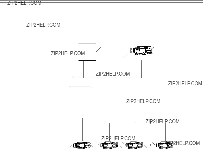
Setting the Time Data
Locking the Time Code to an External Source
When mounting the Time code input/output/Video input adaptor
Example of connections for external locking
Example 1: Locking the time code to an external signal
TC OUT
REF
External REF
TC IN
Example 2: Connecting multiple units and using one unit as the reference
REF
GENLOCK IN
TC REF
??? 77 ???

Setting the Time Data
External Lock Operation Procedure
3
2
1
1
2
3
Set the POWER switch to ON.
Set the
Set the DISPLAY switch to TC.
4 Supply reference time code and reference video signals with a phase relationship which meets the time code standards to the TC IN and GENLOCK IN connectors, respectively.
This locks the
|Note{
When the external locking operation is performed, the time code is locked instantly to the exter- nal time code and the same value as the external code value appears in the counter display position. Do not set the VTR to recording mode for several seconds until the sync generator has stabilized.
Setting Time Data
User bit setting during external locking
When the time code is locked to an external source, only the time data is locked to the time data of the time code from the external source. Accordingly, the user bit can be set independently for each unit. The user bit can also be locked to the user bit of the time code from the external source.
??Consult your dealer for a detailed explanation.
Releasing the external lock
Stop supplying the external time code and then set the
Switching the power supply from the battery to an external power supply during external locking
In order to maintain power supply continuity for the time code generator, connect the external power supply to the DC IN connector before unplugging the battery pack. If the battery pack is unplugged first, the external locking continuity of the time code cannot be assured.
Synchronizing the camera section to an outside source during external locking
While the time code is locked to an external source, the camera section is genlocked by the reference video signal input to the GENLOCK IN connector.
??? 78 ???

Cassettes
Inserting and Ejecting Cassettes
Inserting cassettes
1 Check that there are no cables, etc. around the cassette holder and the top panel and then set the POWER switch to ON.
Power: ON
If condensation has occurred inside the unit, the HUMID display lights. In these cases, wait until the display goes off before proceeding to step 2.
2 Press the EJECT button. The cassette holder opens.
EJECT Button
Cassette Holder
3 Check that there is no slack in the tape, insert the cassette, and then firmly close the cas- sette holder.
Checking that there is no slack in the tape
Press the reel in with your finger and turn it lightly in the direction of the arrow. If the reel does not turn, there is no slack in the tape.
??? 79 ???

Cassettes
Ejecting cassettes
With the power turned on, press the EJECT button to open the cassette holder and eject the cassette. If a cassette is not to be inserted immediately after ejecting the cassette, close the cassette holder.
Ejecting cassettes when the battery has run out
Set the POWER switch to OFF to turn off the power, then turn on the power again and immedi- ately hold down the EJECT button. If there is still power remaining in the battery, the cassette will be ejected. However, this operation should not be repeated.
Preventing Accidental Erasure
Set the tab on the cassette to the SAVE side to prevent the recorded contents of tapes from being accidentally erased.
REC
SAVE
??? 80 ???
Recording
Basic Procedures
This section describes the basic operating procedures for shooting and recording. When starting to shoot actual images, inspect the unit beforehand to check that all systems are functioning normally.
??See the ???Inspections Before Shooting??? (page 120) for a description of inspection procedures.
Procedures from power supply preparations to inserting a cassette
3
2
1
1 Insert a charged battery pack.
2 Set the POWER switch to ON and check that the HUMID display does not appear and that five or more bars of the remaining battery level display are lighted.
??If the HUMID display appears, wait until the display goes off.
??If five or more bars of the remaining battery level display are not lighted, replace the bat- tery pack with a sufficiently charged battery pack.
3 Check that there are no cables, etc. around the cassette holder and top panel and then press the EJECT button to open the cassette holder.
4 Check the following items, and then insert a cassette and close the cassette holder. ??The cassette is not set to write protect status.
??There is no slack in the tape.
??? 81 ???

Recording
Procedures from adjusting the white balance and black balance to stopping recording
Turn on the power, insert a cassette, and then set the various switches as follows.
AUDIO SELECT CH1/CH2: AUTO
TCG:
OUTPUT: CAM/AUTO KNEE ON
GAIN: Normally, set to 0 dB. When it is too dark, it is set to the appropriate gain.
Iris: AUTO
??? 82 ???

Recording
Shooting images
3
2
4,5
Select the filter in accordance with the lighting conditions, and when the white balance has already been stored in the memory, set the WHITE BAL switch to ???A??? or ???B???.
When the white balance and black balance have not been stored in the memory and there is no time to adjust the white balance:
Set the WHITE BAL switch to PRST and set the FILTER knob to ???1???: this will achieve a 3200 K white balance. (If the knob is set to any other position, a 5600 K white balance is achieved.)
To adjust the white balance on site, select the filter which corresponds with the lighting conditions, set the WHITE BAL switch to ???A??? or ???B???, and adjust the white balance by following the steps below.
(1)Press the AUDIO W/B BAL switch to the AWB side to adjust the white balance.
(2)Press the AUTO W/B BAL switch to the ABB side to adjust the black balance.
(3)Press the AUTO W/B BAL switch to the AWB side to adjust the white balance.
For details on how to adjust the white balance, read through the section entitled ???Adjusting the white balance/black balance??? (page 64).
2
3 When using the electronic shutter, set the shutter speed and operation mode. ??See ???Setting the Electronic Shutter??? (page 69) for a detailed description.
4 Press the VTR START button of the unit or the VTR button of the lens to start recording. The REC lamp inside the viewfinder lights during recording.
5 Press the VTR START button again to stop recording. The REC lamp inside the viewfinder goes off.
Tape operation buttons
The tape operation buttons (EJECT, REW, FF, PLAY, STOP) do not function during recording.
??? 83 ???

Recording
Successive Shooting
Successive shooting with an accuracy of within
While recording is paused
The unit automatically searches for the successive shooting point. However, the time until re- cording starts differs according to the setting of the VTR SAVE/STBY switch.
??If the VTR SAVE/STBY switch is set to SAVE, recording starts about 2 seconds after the VTR START button is pressed.
??If the VTR SAVE/STBY switch is set to STBY, recording starts immediately after the VTR START button is pressed.
Successive shooting when the power is turned off while recording is paused
2 1
1
2
Turn the power back on.
Press the VTR START button of the unit or the VTR button of the lens to start recording.
??? 84 ???

Recording
Successive Shooting in Other Cases
If successive shooting is to be performed after the tape has been run, the cassette has been ejected, or when using a tape which has only been recorded
1,2
3
4
Performing successive shooting after the tape has been run, the cassette has been ejected, or when using a tape which has only been recorded
1
2 At the place where continuity between frames is to be provided, press the PLAY (or STOP) button again to stop the tape.
3 Press the RET button on the lens. Preparations for
4 Press the VTR START button of the unit or the VTR button of the lens to start recording.
??? 85 ???

Pressing the PLAY button allows
??Rec review: If the RET VIDEO switch is set to the INT side,
??Color playback: Connecting a color monitor to the unit???s VIDEO OUT connector allows color playback images to be viewed on the monitor.
The playback signal is output to the viewfinder even during rewind (REW) and fast forward (FF). Audio output selection and volume adjustment for the playback signal are performed by the MONITOR switches and knobs on page 13.
Rec Review
If recording is paused and the RET button on the lens is pressed, the tape is automatically re- wound and the playback images for the last two seconds appear on the viewfinder. This allows the recording status to be checked.
After playback, the unit returns to the recording start standby status. Holding down the RET but- ton rewinds and plays back up to 10 seconds of the tape.
|Note{
The rec review function cannot be used unless recording has been performed for more than 1 second.
Color Playback
Connecting a color monitor to the VIDEO OUT connector of the unit allows color playback im- ages to be viewed on the monitor.
??? 86 ???

Connection With an External VTR
The unit is equipped with an interface which enables recording to be performed by an external VTR.
??Mounting the
Precautions When Connecting an External VTR
Set 26P CONTROL on the FUNCTION 3/5 page of the setting menu to BOTH or ON. (The set- ting is OFF when shipped from the factory.)
Power supply
Power is not supplied or received between the unit and the external VTR, so special power sup- plies should be provided for each unit. The BATT lamp and remaining battery level display func- tion inside the viewfinder indicate the power supply status only for the internal VTR. The power supply status for the external VTR should be checked at the external VTR.
TALLY lamp and REC lamp operation
The unit???s TALLY lamp and the REC lamp inside the viewfinder indicate the REC status of the unit when 26P CONTROL is set to BOTH. When 26P CONTROL is set to ON, these lamps indi- cate the REC status of the external VTR.
Warning tone
External
Note on connecting cables
The signals may not be connected properly with some cables.
The signal assignments for the
??? 87 ???

Recording Simultaneously with the Internal VTR and an External
VTR
Connections
Mount the
SW3101 and SW3102 on the CAM ENC Printed Circuit Board of the unit must be set to the 26P side. (See page 90.)
Audio input level selector switch: p60 dB
Portable VTR (Set the audio input level
selector switch to p60 dB.)
Checking the Function Settings
To the
(See page 90 for mounting the
Check that the settings of the functions which control the
Starting Recording
1 Operate the external VTR and set it to recording paused status.
2 Press the VTR START button of the unit or the VTR button of the lens. The internal and external VTRs start recording simultaneously. Pressing the button again sets both VTRs to the recording paused status.
If One VTR Comes to the End of its Tape During Recording
Even if one VTR comes to the end of its tape and stops, the other VTR continues recording op- eration.
Returning the VTRs to simultaneous recording status
??If the internal VTR came to the end of its tape, replace the cassette and press the VTR START button of the unit or the VTR button of the lens. The external VTR continues recording opera- tion during this time.
??If the external VTR came to the end of its tape, replace the cassette and operate the external VTR to restart recording. The internal VTR continues recording operation during this time.
|Note{
Care should be taken as the internal VTR will assume recording paused status if the VTR START button of the unit or the VTR button of the lens is pressed after replacing the external VTR???s cassette.
??? 88 ???

Recording Simultaneously with the Internal VTR and an External
VTR
Functions of the Unit???s VTR SAVE/STBY Switch
Tape running mode
Pressing the unit???s STOP, REW or FF buttons sets the internal VTR to stop, rewind or fast for- ward modes, respectively. However, the external VTR is set to recording paused status in all cases.
Viewing playback images on the viewfinder
Pressing the unit???s PLAY button allows
??? 89 ???

Recording With an External VTR Instead of the Internal VTR
Using the
Connections
The method of connecting the external VTR is the same as that described in ???Recording Simul- taneously with the Internal VTR and an External VTR???.
??See ???Connections??? on page 87.
Mounting the
??Consult your local dealer when mounting the adaptor.
1 Set the unit???s internal switches.
1Remove the side panel on the display window side.
2Remove the Printed Circuit Board holder and remove the CAMERA ENC Printed Circuit Board.
3Set SW101 and SW102 to the 26P side.
CAM ENC Printed Circuit Board
Printed Circuit
Board Holder
SONY SONY
MII MII
 26P
26P
SW102
 26P
26P
SW101
CAM ENC Printed Circuit Board
2 Mount the
(Illustration of
??? 90 ???
Recording With an External VTR Instead of the Internal VTR
Controlling the external VTR with the unit???s switches
Setting the 26P CONTROL function as indicated below at the FUNCTION 3/5 page of the set- ting menu prevents the internal VTR from being operated and enables only the external VTR to be controlled by the VTR START button of the unit or the VTR button of the lens.
??26P CONTROL: ON
??See ???Selecting Functions??? (page 63) for a description of FUNCTION 3/5 page operations.
Switching from the internal VTR to the external VTR
If the internal VTR experiences problems (tapes becoming tangled, condensation, etc.) during operation and becomes unable to operate, the VTR START button of the unit and the VTR but- ton of the lens will not function. In these cases, setting the 26P CONTROL function as noted above at the FUNCTION 3/5 page allows the external VTR to be operated in place of the inter- nal VTR using the VTR START button of the unit or the VTR button of the lens.
Starting recording
Operate the external VTR to set it to recording paused status and press the VTR START button of the unit or the VTR button of the lens. The external VTR starts recording. Pressing the button again sets the VTR to the recording paused status.
Output level of the
When the unit is shipped from the factory, the audio level is set to p60 dBu balanced and the component video level is set to Sony level (see page 90). The audio level can be set to p20 dBu unbalanced and the component video level to MII level with an internal switch. Consult your dealer for a detailed description.
??? 91 ???

RET Button
The images recorded on the VTR or return video signal which has been input to the Time code input/output/Video input adaptor
What is displayed on the viewfinder screen changes as indicated in the table below according to the RET VIDEO switch setting and VTR mode.
?? Lens RET button functions
??? 92 ???

Replacing the Backup Battery
The unit is shipped from the factory with a backup battery already mounted. When the battery runs out, the TCG time code value indicates 00:00:00:00.
At this time, the time code value cannot be backed up.
In addition, the ???BACK UP BATT EMPTY??? display appears in the viewfinder for 3 seconds when the POWER switch is set to ON to indicate that the battery must be replaced.
Consult your dealer when replacing the battery.
Backup Battery
??? 93 ???

Setting Menu Screens
MARKER Screen
This page sets the setting for the marker displays inside the viewfinder.
- MARKER -
?????CENTER MARK : ON
SAFETY ZONE : 1
Menu screen display methods
The underlined setting in the Variable range column indicates the preset mode.
USER menu: Setting the MENU switch to SET displays the USER menu.
ENG menu: Holding down the SHIFT/ITEM and UP buttons simultaneously and setting the MENU switch to SET displays the ENG menu.
??? 94 ???

Setting Menu Screens
VF DISPLAY Screen
This page sets the setting for the display information inside the viewfinder.
Menu screen display methods USER menu: Setting the MENU
switch to SET displays the USER menu.
ENG menu: Holding down the SHIFT/ITEM and UP buttons simultaneously and setting the MENU switch to SET displays the ENG menu.
The underlined setting in the Variable range column indicates the preset mode.
??? 95 ???

Setting Menu Screens
CAMERA ID Screen
This page performs the camera ID settings. Each time the UP button is pressed, the character display changes in the order of space, English letters (A to Z), numbers (0 to 9) and symbols [space, {, |, ), (, ???, ???, ,,
- CAMERA I D -
???
I D : E E E E E E E E E E
|Note{
Whether or not this set value is to be mixed is selected by setting CAMERA ID on the VF DISPLAY screen to ON or OFF.
SHUTTER SPEED Screen
This page performs the shutter speed settings. The ON/OFF status for each item is indicated by displaying an asterix (E) or period (.) in front of the item on the screen.
The underlined setting in the Variable range column indicates the preset mode.
Menu screen display methods
USER menu: Setting the MENU switch to SET displays the USER menu.
ENG menu: Holding down the SHIFT/ITEM and UP buttons simultaneously and setting the MENU switch to SET displays the ENG menu.
??? 96 ???

Setting Menu Screens
SYNCHRO SCAN Screen
This page performs the synchro scan settings.
! LED Screen
This page sets the ON/OFF setting for the ! LED display inside the viewfinder. The ON/OFF status for each item is indicated by displaying an asterix (E) or period (.) in front of the item on the screen.
- ! L ED -
?????EGA I N ( 0 d B )
. GA I N ( - 3 d B )
ESHUT TER
. WH I TE PRESET
EEXTENDER
. F I L TER
. SUPER V
E: ON
. : OFF
|Note{
The ! LED lights when both GAIN (0 dB) and GAIN (p3 dB) are ON unless the gain is set to p3 dB or 0 dB.
The underlined setting in the Variable range column indicates the preset mode.
Menu screen display methods
USER menu: Setting the MENU switch to SET displays the USER menu.
ENG menu: Holding down the SHIFT/ITEM and UP buttons simultaneously and setting the MENU switch to SET displays the ENG menu.
??? 97 ???

Setting Menu Screens
MAIN FUNCTION Screen
This page performs the adjustment function settings.
BATT/TAPE ALARM Screen
The battery end and tape end audio warnings during shooting can be switched off if they become undesirable.
The underlined setting in the Variable range column indicates the preset mode.
Menu screen display methods
USER menu: Setting the MENU switch to SET displays the USER menu.
ENG menu: Holding down the SHIFT/ITEM and UP buttons simultaneously and setting the MENU switch to SET displays the ENG menu.
??? 98 ???

Setting Menu Screens
FUNCTION 1/5 Screen
This page performs the adjustment function 1 settings. The ON/OFF status for each item is indicated by displaying an asterix (E) or period (.) in front of the item on the screen.
FUNCTION 2/5 Screen
This page performs the adjustment function 2 settings.
USHOCKLESS AWB ensures that no shock will occur when A/B/PRST set- ting of the WHITE BAL switch is changed. FAST (high speed), NORMAL
(normal speed) or SLOW (low speed) can be set as the selection time.
The underlined setting in the Variable range column indicates the preset mode.
Menu screen display methods
USER menu: Setting the MENU switch to SET displays the USER menu.
ENG menu: Holding down the SHIFT/ITEM and UP buttons simultaneously and setting the MENU switch to SET displays the ENG menu.
??? 99 ???

Setting Menu Screens
FUNCTION 3/5 Screen
This page performs the adjustment function 3 settings.
FEven if the BATTERY SEL is selected to
??? 100 ???
Setting Menu Screens
FUNCTION 4/5 Screen
This page performs the adjustment function 4 settings.
The underlined setting in the Variable range column indicates the preset mode.
Menu screen display methods
USER menu: Setting the MENU switch to SET displays the USER menu.
ENG menu: Holding down the SHIFT/ITEM and UP buttons simultaneously and setting the MENU switch to SET displays the ENG menu.
??? 101 ???

Setting Menu Screens
FUNCTION 5/5 Screen
This page performs the adjustment function 5 settings.
TIME DATE Screen
This page performs the date and time settings. After the date and time have been changed, pressing the UP or DOWN buttons
executes the settings.
|Note{
The seconds cannot be set. The time always starts from the zero second setting.
The underlined setting in the Variable range column indicates the preset mode.
Menu screen display methods
USER menu: Setting the MENU switch to SET displays the USER menu.
ENG menu: Holding down the SHIFT/ITEM and UP buttons simultaneously and setting the MENU switch to SET displays the ENG menu.
??? 102 ???

Setting Menu Screens
LOW SETTING Screen
This page sets the low level.
|Note{
DARK DTL and LEVEL DEPEND function in a mutually opposite way: LEVEL DEPEND is automatically set to 0 when DARK DTL is set to a value other than 0; and DARK DTL is automatically set to 0 when LEV- EL DEPEND is set to a value other than 0.
The underlined setting in the Variable range column indicates the preset mode.
Menu screen display methods
USER menu: Setting the MENU switch to SET displays the USER menu.
ENG menu: Holding down the SHIFT/ITEM and UP buttons simultaneously and setting the MENU switch to SET displays the ENG menu.
??? 103 ???

Setting Menu Screens
MID SETTING Screen
This page sets the middle level.
|Note{
DARK DTL and LEVEL DEPEND function in a mutually opposite way: LEVEL DEPEND is automatically set to 0 when DARK DTL is set to a value other than 0; and DARK DTL is automatically set to 0 when LEV- EL DEPEND is set to a value other than 0.
The underlined setting in the Variable range column indicates the preset mode.
Menu screen display methods
USER menu: Setting the MENU switch to SET displays the USER menu.
ENG menu: Holding down the SHIFT/ITEM and UP buttons simultaneously and setting the MENU switch to SET displays the ENG menu.
??? 104 ???

Setting Menu Screens
HIGH SETTING Screen
This page sets the high level.
- H I GH SET T I NG -
|Note{
DARK DTL and LEVEL DEPEND function in a mutually opposite way: LEVEL DEPEND is automatically set to 0 when DARK DTL is set to a value other than 0; and DARK DTL is automatically set to 0 when LEV- EL DEPEND is set to a value other than 0.
The underlined setting in the Variable range column indicates the preset mode.
Menu screen display methods
USER menu: Setting the MENU switch to SET displays the USER menu.
ENG menu: Holding down the SHIFT/ITEM and UP buttons simultaneously and setting the MENU switch to SET displays the ENG menu.
??? 105 ???

Setting Menu Screens
LEVEL 1/6 Screen
This page performs the camera setup level 1 settings.
UIt detects the chroma edge and places on Y to boost the H detail. The higher the number selected, the greater the compensation.
LEVEL 2/6 Screen
This page performs the camera setup level 2 settings.
UThis sets the range of the colors han- dled as the skin tone on the basis of the colors set by SKIN TONE HUE and LEVEL. The higher the number select- ed, the wider the skin tone range.
|Note{
Only numbers are displayed while the variable range of any item except SKIN
TONE ZEBRA ON/OFF is being changed.
The underlined setting in the Variable range column indicates the preset mode.
Menu screen display methods
USER menu: Setting the MENU switch to SET displays the USER menu.
ENG menu: Holding down the SHIFT/ITEM and UP buttons simultaneously and setting the MENU switch to SET displays

Setting Menu Screens
LEVEL 3/6 Screen
This page performs the camera setup level 3 settings.
The underlined setting in the Variable range column indicates the preset mode.
Menu screen display methods
USER menu: Setting the MENU switch to SET displays the USER menu.
ENG menu: Holding down the SHIFT/ITEM and UP buttons simultaneously and setting the MENU switch to SET displays the ENG menu.
??? 107 ???

Setting Menu Screens
LEVEL 4/6 Screen
This page performs the camera setup level 4 settings.
- L EVE L 4 / 6 -
The R FLARE, G FLARE and B FLARE will not be initialized even when the initial- ization (default setting) operation is performed.
The underlined setting in the Variable range column indicates the preset mode.
Menu screen display methods
USER menu: Setting the MENU switch to SET displays the USER menu.
ENG menu: Holding down the SHIFT/ITEM and UP buttons simultaneously and setting the MENU switch to SET displays the ENG menu.
??? 108 ???

Setting Menu Screens
LEVEL 5/6 Screen
This page performs the camera setup level 5 settings.
|Note{
The white balance and black balance remain unchanged even when the MATRIX items are changed.
The underlined setting in the Variable range column indicates the preset mode.
|Note{
All settings are ???00??? for the preset mode of MATRIX TABLE B.
Menu screen display methods
USER menu: Setting the MENU switch to SET displays the USER menu.
ENG menu: Holding down the SHIFT/ITEM and UP buttons simultaneously and setting the MENU switch to SET displays the ENG menu.
??? 109 ???

Setting Menu Screens
LEVEL 6/6 Screen
This page performs the camera setup level 6 settings.
The underlined setting in the Variable range column indicates the preset mode.
Menu screen display methods
USER menu: Setting the MENU switch to SET displays the USER menu.
ENG menu: Holding down the SHIFT/ITEM and UP buttons simultaneously and setting the MENU switch to SET displays the ENG menu.
??? 110 ???
Setting Menu Screens
VF OPERATION Screen
This page performs the viewfinder display settings.
The underlined setting in the Variable range column indicates the preset mode.
Menu screen display methods
USER menu: Setting the MENU switch to SET displays the USER menu.
ENG menu: Holding down the SHIFT/ITEM and UP buttons simultaneously and setting the MENU switch to SET displays the ENG menu.
??? 111 ???

Setting Menu Screens
LENS ADJ Screen
This page performs the lens adjustments. The ON/OFF status for each item is indicated by displaying an asterix (E) or period (.) in front of the item on the screen.
E: ON
. : OFF
|Note{
When using a lens which allows the lens iris open or close end to be adjusted, set either ???F2.8 ADJ??? or ???F16 ADJ??? to ON and repeatedly adjust the lens iris until it is ???F2.8??? or ???F16???, respectively. (Fujinon S18 q6.7 BRM4/BERM4 lenses do not have this adjustment function.)
MENU SELECT 1/3 Screen
This page performs the menu page display ON/OFF settings. The ON/OFF status for each item is indicated by displaying an asterix (E) or period (.) in front of the item on the screen.
The underlined setting in the Variable range column indicates the preset mode.
Menu screen display methods
USER menu: Setting the MENU switch to SET displays the USER menu.
ENG menu: Holding down the SHIFT/ITEM and UP buttons simultaneously and setting the MENU switch to SET displays the ENG menu.
??? 112 ???

Setting Menu Screens
MENU SELECT 2/3 Screen
This page performs the menu page display ON/OFF settings. The ON/OFF status for each item is indicated by displaying an asterix (E) or period (.) in front of the item on the screen.
The underlined setting in the Variable range column indicates the preset mode.
Menu screen display methods
USER menu: Setting the MENU switch to SET displays the USER menu.
ENG menu: Holding down the SHIFT/ITEM and UP buttons simultaneously and setting the MENU switch to SET displays the ENG menu.
??? 113 ???

Setting Menu Screens
MENU SELECT 3/3 Screen
This page performs the menu page display ON/OFF settings. The ON/OFF status for each item is indicated by displaying an asterix (E) or period (.) in front of the item on the screen.
The underlined setting in the Variable range column indicates the preset mode.
Menu screen display methods
USER menu: Setting the MENU switch to SET displays the USER menu.
ENG menu: Holding down the SHIFT/ITEM and UP buttons simultaneously and setting the MENU switch to SET displays the ENG menu.
??? 114 ???

Setting Menu Screens
AUTO SHADING Screen
This page performs the auto shading settings. Align the arrow with the desired BLACK or WHITE item and press the UP or
DOWN button to execute the setting.
- AUTO SHAD I NG -
DATA RESET Screen
The underlined setting in the Variable range column indicates the preset mode.
This page resets the menu display item settings. Aligning the cursor (arrow) with the item and pressing the UP or DOWN button resets the settings.
DIAGNOSTIC Screen
This page displays the unit???s operating conditions and software version.
Menu screen display methods
USER menu: Setting the MENU switch to SET displays the USER menu.
ENG menu: Holding down the SHIFT/ITEM and UP buttons simultaneously and setting the MENU switch to SET displays the ENG menu.
??? 115 ???

Warning System
If trouble is detected immediately after the power is turned on or during operation, the display window (LCD), WARNING lamp, lamps inside the viewfinder, and warning tones from the speaker and earphone inform the operator of trouble.
|Note{
If a cleaning tape is not available to deal with video head clogging, etc., first es- tablish the STOP mode and then press the STOP button again while the RESET button on the side panel is kept depressed. While these buttons are held down, the cleaning roller will clean the heads for a maximum of 10 seconds.
??? 116 ???

Warning System
F1) During recording
F2) During playback, fast forward or rewind
|Notes{
??When trouble occurs with the external VTR connected to the unit, warnings are displayed only by the unit???s REC and TALLY lamps.
??When connecting the external VTR to the
Warning system priorities are as follows.
1SLACK
2BATTERY END
3TAPE END
4BATTERY NEAR END
5TAPE NEAR END
6HUMID
7SERVO
8RF
??? 117 ???

Emergency eject
If the cassette cannot be ejected by pressing the EJECT button, use a screwdriver or similar tool to press and turn the EMERGENCY screw. This enables the cassette to be removed.
1 Set the power to OFF.
2
3 While pushing in with the screwdriver, turn the EMERGENCY screw counterclockwise until the tape is ejected.
1This screw needs to be rotated through about 30 turns after the first turn until the unload- ing can be started.
2This screw needs to be rotated through about 120 turns after the first turn until the tape is ejected.
4 Remove the cassette.
5 Return the rubber cap to its original position.
|Notes{
1.Do not turn the EMERGENCY screw except in an emergency.
2.Do not turn the screw clockwise. Stop turning the screw as soon as the tape is ejected. Otherwise, the mechanism may be damaged.
3.After the tape is ejected, the cassette holder will not lock into placed even when an attempt is made to close it. Be sure to turn the power off and turn it back on to reset the mechanism???s operation, and then close the cassette holder.
4.A clicking sound will be heard when the EMERGENCY screw is turned: this sound is made by the real drive operation and is therefore not indicative of a malfunction.
Cassette holder
Error Codes
When an error occurs in the unit for some reason or other, the following error codes appear in the display window.
??? 118 ???
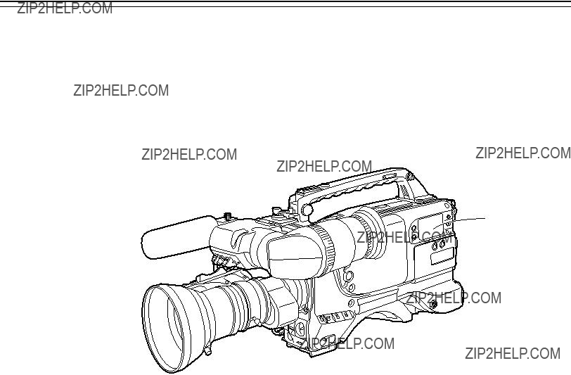
Maintenance
Condensation
If the unit is moved from a cold location to a warm location or used in areas with high humidity, the moisture in the air may adhere as water droplets on the head drum. This is called condensa- tion, and if the tape is run under these conditions, it will easily stick to the drum. Therefore, the following points should be observed.
??If the unit is moved under conditions where condensation may occur, eject the tape.
??Before inserting the tape, set the POWER switch to ON and check that the HUMID display in the display window is not lighted. If the HUMID display is lighted, do not insert the tape until the display goes off.
The HUMID display
is not lighted.
Cleaning the Video Heads
Use the
Cleaning the Viewfinder
??Do not use thinner or other solvents to remove dirt from the viewfinder. ??Wipe the lens with lens cleaner available on the market.
??Absolutely do not wipe the mirror. If dirt, etc. has adhered to the mirror, remove it using a air blower available on the market.
Characteristic Phenomenon of CCD Cameras
Smear
Smear occurs when shooting
??? 119 ???
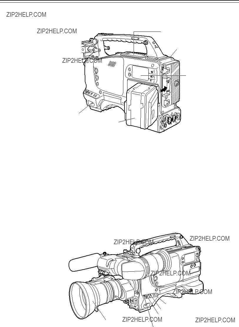
Inspections Before Shooting
Perform the following inspections before shooting to check that all systems are operating prop- erly. Checking the image with a color monitor is recommended.
Inspection Preparations
3
4
2
2
1
1
2 Set the POWER switch to ON and check that the HUMID display does not appear and that five or more bars of the remaining battery level display are lighted.
??If the HUMID display appears, wait until the display goes off.
??If five or more bars of the remaining battery level display are not lighted, replace the bat- tery pack with a sufficiently charged battery pack.
3 Check that there are no cables, etc. around the cassette holder and top panel, and then press the EJECT button to open the cassette holder.
4 Check the following items, and then insert a cassette and close the cassette holder. ??The cassette is not set to the write protect status.
??There is no slack in the tape.
Inspecting the Camera Section
Set the switches as follows.
Iris: AUTO
Zoom: AUTO
WHITE BAL: A or B
OUTPUT: BARS
Gain: Normally, set to 0 dB. When it is too dark, it is set to the appropriate gain.
VTR SAVE/STBY: STBY
??? 120 ???
Inspections Before Shooting
Inspecting the Viewfinder
1
2 Check that the color bar appears on the viewfinder screen, and then adjust the BRIGHT, CONTRAST and PEAKING controls so that the color bar appears clearly on the viewfinder.
3 Check the following items.
(1)Set the MENU SET/OFF switch to SET and check that the setting menu appears on the viewfinder screen.
(2)Press the PAGE button and check that the setting menu page changes.
(3)Press the SHIFT/ITEM switch and check that the cursor moves within the page.
(4)Press the UP or DOWN button to check that the setting or ON/OFF display of the item selected with the cursor changes.
4 Set the OUTPUT/AUTO KNEE switch to CAM and switch the FILTER knob to 1, 2, 3 and 4. Check that the number of the FILTER display on the viewfinder screen changes in accor- dance with the knob position.
5 Perform the following operations to check that the (!) lamp lights when the items set to ON at the (!) LED page are operated.
(1)Set the gain to any value other than 0 dB with the GAIN switch.
(2)Set the SHUTTER switch to ON.
(3)Set the WHITE BAL switch to PRST.
(4)Insert the lens extender.
(5)Set the FILTER knob to any position other than ???1???.
6 Press the SHUTTER switch repeatedly from the ON position to the SEL side and check that the shutter setting on the viewfinder screen changes.
7 Aim the lens at an appropriate subject and turn the focus ring to bring the subject into focus. Check the image appearing in the viewfinder.
8 Set both the AUDIO IN CH1 and CH2 switches to FRONT [MIC] and set LEVEL METER on the VF DISPLAY page of the setting menu to ON. Check that the audio level appears on the viewfinder screen when sound is input from the microphone connected to the MIC IN jack on the front panel. Then, check that the audio level disappears from the viewfinder screen when LEVEL METER on the VF DISPLAY page of the setting menu is set to OFF.
9 Check that the zebra pattern appears on the viewfinder screen when the ZEBRA switch is set to ON, and disappears when the ZEBRA switch is set to OFF.
|Note{
The items and functions in steps 3 to 6 may not be displayed or may not operate depending on the setting conditions. Set the unit to engineer mode, set DISPLAY MODE on the VF DISPLAY page of the setting menu to ???3???, and then set the required items at the SHUTTER SPEED, (!) LED and MENU SELECT 1/3 to 3/3 pages.
??? 121 ???

Inspections Before Shooting
Inspecting the Iris and Zoom Functions
1
2
3
4
5
6 Return the iris to automatic adjustment mode and change the GAIN switch setting toL, M and H to check the following items.
??The iris is adjusted with respect to subjects with the same brightness in accordance with the switch setting.
??The gain value display on the viewfinder screen changes in accordance with the switch setting.
7 When a lens with an extender is mounted, set the extender to the used position to check that the extender functions properly.
Perform ???(1) Tape Running Inspections??? to ???(4) Earphone and Speaker Inspections??? below consecutively.
Inspecting the VTR Section
(1)Tape Running Inspections
1Set the VTR SAVE/STBY switch to SAVE and check that the VTR SAVE lamp inside the viewfinder lights.
2Set the VTR SAVE/STBY switch to STBY and check that the VTR SAVE lamp goes off.
3Set the
4Set the DISPLAY switch to CTL.
5Press the unit???s VTR START button and check the following items. ??The tape reels turn.
??The counter display number changes. ??The REC lamp inside the viewfinder lights.
??The RF and SERVO lamps in the display window do not light.
6Press the unit???s VTR START button again. Check that the tape stops and the REC lamp inside the viewfinder goes off.
7Check the same operations as in steps 5 and 6 using the VTR button of the lens.
8Press the RESET button and check that the counter display number changes to ???00:00:00:00???.
9Set the LIGHT switch to ON and check that the display window is illuminated.
10 Press the REW button and then press the PLAY button after the tape has rewound for a while. Check that the recording, playback and rewind operations are performed properly.
11 Press the FF button and check that fast forward operation is performed properly.
??? 122 ???

Inspections Before Shooting
(2) Inspection of Audio Level Automatic Adjustment Functions
1
2
Set the AUDIO SELECT CH1/CH2 switch to AUTO.
Set the AUDIO IN CH1/CH2 switch to FRONT [MIC].
3 Aim a microphone connected to the MIC IN jack at an appropriate sound source and check that the level display for both CH1 and CH2 changes in accordance with the sound level.
(3) Inspection of Audio Level Manual Adjustment Functions
1
2
Set the AUDIO IN CH1/CH2 switch to FRONT [MIC].
Set the AUDIO SELECT CH1/CH2 switch to MAN.
3 Turn the AUDIO LEVEL CH1/CH2 controls and check that the level display increases when the controls are turned to the right.
(4) Earphone and Speaker Inspections
1
2
3 Connect an earphone to the PHONES jack. Check that the sound to the speaker is cut off and that the microphone sound can be heard from the earphone.
4 Turn the MONITOR control and check that the earphone volume changes.
(5) Inspections when Using an External Microphone
1
2
Connect an external microphone to the AUDIO IN CH1 and CH2 connectors.
Set the AUDIO IN CH1/CH2 switch to REAR [MIC].
3 Aim the microphone at a sound source and check that the audio level meter in the display window and the audio level display inside the viewfinder change in accordance with the sound level. Each channel can also be checked separately by connecting a single micro- phone to each channel.
(6)Time Code and User
1Set the user bit as necessary.
??See ???Setting the User Bit??? (page 76) for a description of setting methods.
2Set the time code.
??See ???Setting the Time Code??? (page 75) for a description of setting methods.
3Set the
4Press the VTR START button.
Check that the tape runs and the counter display number changes.
5Press the VTR START button again.
Check that the tape stops and the counter display number stops changing.
6Set the
Check that the counter display number changes regardless of the tape running status.
7Set the DISPLAY switch to UB.
Check that the set user bit is displayed.
???123 ???

Specifications
General
??? 124 ???

Specifications
VTR Section
VTR Video System (during playback on a standard playback unit)
Accessories
Microphone kit
Tripod attachment
Sony battery connector (screw included)
Weight and dimensions shown are approximate.
Specifications are subject to change without notice.
??? 125 ???

Specifications
Related Components
Power supply related
Viewfinder
External
Portable video cassette recorder
Connection cables
??for connecting an external VTR to the
??for connecting an external VTR to the
FVideo input connector can only be used for return video input.
Audio components
Maintenance products
??? 126 ???
??? 127 ???

PANASONIC BROADCAST & DIGITAL SYSTEMS COMPANY
DIVISION OF MATSUSHITA ELECTRIC CORPORATION OF AMERICA
PARTS INFORMATION & ORDERING:
9:00
TECHNICAL SUPPORT:
Emergency 24 Hour Parts & Service (800)
TRAINING INFORMATION:
Digital System Products - (201)
Panasonic Canada Inc.
5770 Ambler Drive, Mississauga, Ontario L4W 2T3 (905)
Panasonic de Mexico S.A. de C.V.
Av angel Urraza Num. 1209 Col. de Valle 03100 Mexico, D.F. (52) 1 951 2127