ORDER NO. PTD0108U32C1
F16
Cordless Multi Drill & Driver
SPECIFICATIONS
?? 2001 Matsushita Electric Works Ltd. All rights reserved. Unauthorized copying and distribution is a violation of law.
ORDER NO. PTD0108U32C1
F16
Cordless Multi Drill & Driver
SPECIFICATIONS
?? 2001 Matsushita Electric Works Ltd. All rights reserved. Unauthorized copying and distribution is a violation of law.

CONTENTS
1SCHEMATIC DIAGRAM
2WIRING CONNECTION DIAGRAM
2

3 DISASSEMBLY INSTRUCTIONS
???HOW TO DISASSEMBLE THE MAIN UNIT.
3
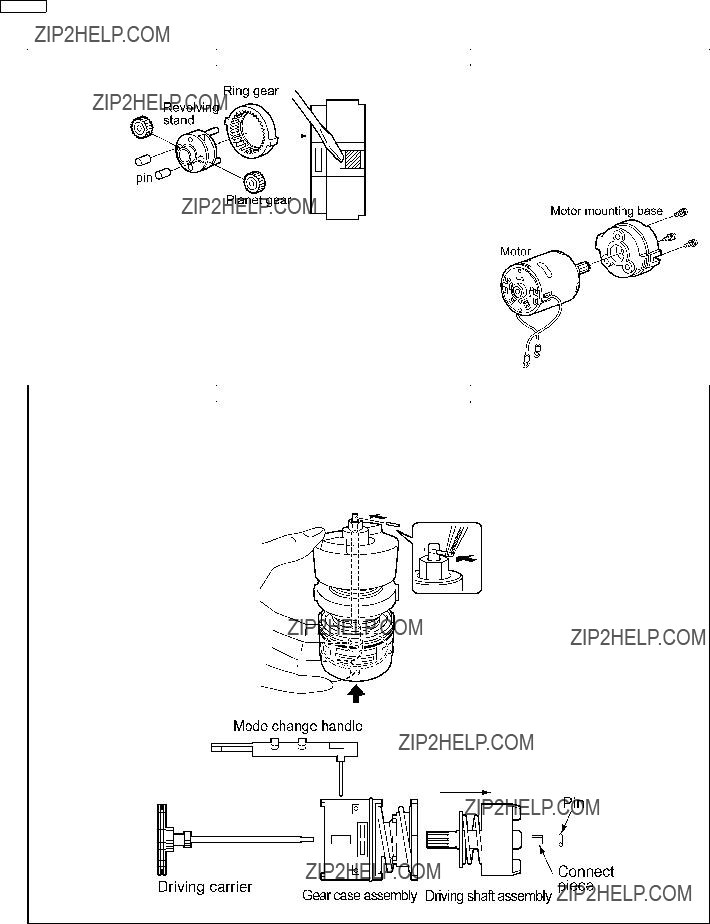
1. Hold the driving carrier as illustrated. Compress the assembly and remove the pin. 2. Take out the driving shaft assembly and the gear case assembly from the shaft of the driving carrier.
NOTE :
Make sure not to lose the pin and the connect piece.
4

thrust plate ??? clutch gear ??? planet gear (3pcs) ??? carrier ??? thrust plate
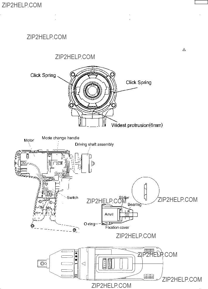
4. Remove adjusting screw, clutch spring, and clutch plate.
5. After removing the clutch plate, 6 pieces of steel ball come off.
5

4 ASSEMBLY INSTRUCTIONS
6

7

1. Fit terminal of lead wire (black) parallel to the heat sink.
Caution:
Be careful that the heat sink and the terminal do not touch, otherwise these are shortcuircuit.
8
9
5 TROUBLESHOOTING GUIDE
(Refer to WIRING CONNECTION DIAGRAM)
10
???Even if FET block is defective, it can not be replaced individually. Replace whole switch block.
Shortcircuit (G: gate) and (S: source), and measure between it and (D: drain) with switch block.
NOTE:
*FET is sensitive against static electricity.
**The resistance value will vary dependent upon the measurement range of the tester.
???OK
< REMEDY > NO Replace switch & FET
???block.
11

6 EXPLODED VIEW
12
7 REPLACEMENT PARTS LIST
NOTE:
*A = available as an optional accessory *B = only available as set
*C = available individually
**Battery Pack, Keyless Chuck, Quick Change Chuck and Tool Case are available as an optional accessory. " See the nearest sales dealer for details.
***For replacement parts of charger, see the charger service manual.
13