
To an
The
In addition, it offers full manual exposure control at the flip of a lever switch.
1
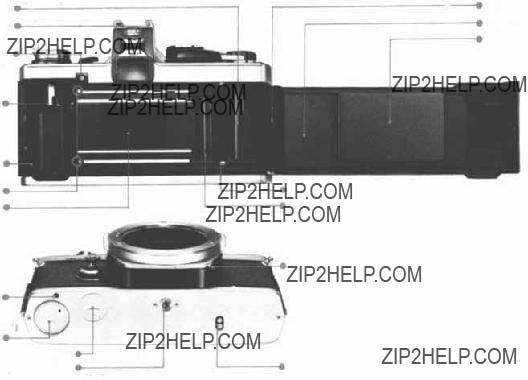
DESCRIPTION OF CONTROLS
Refer to pages in parentheses for detailed explanations of each part.
Film
Spool (P.58)
Viewfinder
Eyepiece Frame
Battery (P . 8)
Check Lamp
Rewind Shaft
Film Chamber
Motor (P. 37, P. 40)
Guide Pin Hole
Battery (P. 7)
Chamber
Motor Drive Socket Cap
Tripod Socket
(P.37, P40)
(P. 37)
(P. 27) Camera Back
Release Pin
(P. 9)
Camera Back
Pressure Plate
Recordata Back Contact
Dual Sprocket
B LOCK Button
(P. 12)
Motor Coupling Terminal
2

Manual Shutter
Speed Ring
Lens Release Button
FP and X Flash Synch Selector
Flash Synchronization Socket
Rewind Knob
/Camera Back Release
Rewind Crank
(P.9, P.20, P. 44)
Selector Lever
Hot Shoe Socket
(P. 12)
(P. 7)
(P.30, P.35)
(P.35)
(P.20)
(P. 8, P.15, P. 24, P44)
(P.26)
(P. 12, P.15, P.16, P. 17. P. 18, P. 35)
(P. 14)
(P.26)
(P. 11. P.23)
(P.19, P.20, P.37, P.42, P.44)
(P. 11)
(P. 10)
(P. 11)
Depth of Field Scale
Aperture Ring
Focusing Ring
Lens Mount Ring
Body Mount Ring
Exposure Copensation
Dial/Film Speed Dial
Shutter Release Button
/Cable Release Socket
Exposure Counter
(P. 10, P. 20)
ASA Film Speed
Window
Film Advance Lever
Memo Holder
3

Rewind Release Lever
Preview Button
(P.20, P.44)
(P.21, P.44)
(P. 25, P. 26.)
Accessory Shoe 4
Shoulder Strap Eyelet
Lens
4

TABLE OF CONTENTS
Focusing . . . . . . . . . . . . . . . . . . . . . 14
Automatic Exposure Control . . . . . . . . . 15
Manual Exposure Control . . . . . . . . . . . 17
Holding the Camera . . . . . . . . . . . . . . 19 Unloading the Camera/Making Multiple
Exposures . . . . . . . . . . . . . . . . . . . 20 Setting the
Measurement . . . . . . . . . . . . . . . . . 23
Exposure Compensation for Manual
Measurement . . . . . . . . . . . . . . . . . 24
Depth of Field . . . . . . . . . . . . . . . . . 25
Depth of Field Scale/Preview Button . . . . 26
Infrared Photography/Camera Back
Replacement . . . . . . . . . . . . . . . . . 27
Interchangeable Focusing Screens . . . . . . 28 Flash Photography with the T32 (T20)
Electronic Flash . . . . . . . . . . . . . . . 29
5

Flash Bulb Photography . . . . . . . . . . . . 36
Motor Drive Photography . . . . . . . . . . . 37
Winder 2 Operation . . . . . . . . . . . . . . 40
Care and Storage . . . . . . . . . . . . . . . . 42
Questions and Answers . . . . . . . . . . . . 44
The Most Important Feature of the
Measuring . . . . . . . . . . . . . . . . . . . 47
6

Mount the Lens.
Align the red dots on the lens flange and the body mount ring. Turn the lens clockwise until the lens release button springs up and you will hear posi- tive "click".
Lens Removal
To detach the lens, press down on the lens release button and turn the lens
Insert two 1.5V silver oxide batteries SR44 (Eveready
CAUTION: Batteries should be always replaced
as a pair. If battery polarity is incorrect, the cam- era does not function.
7

BATTERY CHECK AND MIRROR
By pressing the selector lever to the "CHECK??? RESET" position, you can check the batteries
and/or unlock the mirror.
Check the Batteries.
Move the selector lever to the "CHECK???RESET"
position. The battery check lamp indicates bat-
tery condition as follows:
 The red lamp lights brightly ??? Battery volt- age is sufficient.
 The red lamp flashes on and off ??? Batteries are very weak. Fresh batteries are recommended.
  The lamp does not light ??? Batteries are drain- ed. Replace them.
NOTE: Silver oxide batteries will last approxi-
mately one year. To avoid battery drain, make it
a point to switch off the selector lever when the
camera is not used.
Mirror
If the mirror is up, the field of view turns dark
through the viewfinder, and the film cannot be
advanced. This
 no batteries are loaded or batteries are deplet-
ed, or  the film is advanced during exposure. The mirror
down of the camera, but a
the "CHECK???RESET" position, and unlock the mirror. In case  , shooting can be resumed im- mediately. In case
  , replace batteries.
CAUTION: You cannot unlock the mirror after
battery replacement, if you omit pressing the selector lever to the "CHECK???RESET" position.
NOTE: When the mirror locks up, a battery drain
prevention device is activated to conserve power.
8
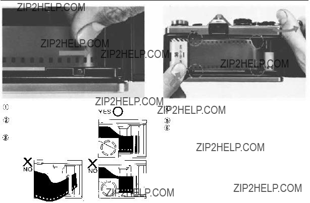
LOADING THE FILM
Pull the rewind knob up
and open the camera back.
Insert a film cartridge into the film chamber and push the rewind knob back.
Insert the film leader into
one of the slots in the film
Turn the advance lever so that the film perfora- tions engage the sprocket teeth.
Close the camera back until it clicks.
Make sure the selector lever is in the OFF posi- tion.
NOTE: Fold out the rewind crank and rotate it clockwise slightly to remove any slack in the film.
Then if the rewind crank rotates as you turn the advance lever, the film is properly advancing.
9
OPERATING THE FILM ADVANCE
LEVER
EXPOSURE COUNTER
Turn the advance lever to the right as far as it will go. The film can be advanced by one frame, in a single stroke or in multiple short strokes.
NOTE: If the advance lever stops moving because you've shot the last remaining film frame while you are advancing the film, discontinue the film
advance and rewind the film. (Read pages 37~41
for motor drive shooting.)
Exposure Counter
The exposure counter is indexed from "S" (Start) to 1, 2 ... up to 36 in even numbers and "E" (End). Whenever the camera back is opened, the exposure counter automatically returns to "S".
10

SETTING THE ASA FILM SPEED DIAL
Lift up the outer collar of the exposure com- pensation dial and rotate until the ASA speed for the film appears in the window.
The ASA film speed scale on the dial is mark-
ed from 12 to 1600. If you are not able to rotate the outer collar to the desired ASA in
one turn of the dial (only 3 stops can be rotated
in one turn of the dial), release the collar and turn the exposure compensation dial several click stops in the opposite direction from the ASA you are trying to set. Then, lift the outer collar again and continue turning to the desir-
ed ASA setting. NEVER FORCE THE DIAL
WHEN SETTING ASA.
Once the setting has been made, turn the dial until the white line is aligned with the black index line on the pentaprism housing.
CAUTION: Make sure you align the white line
with the black index line on the pentaprism after setting ASA.
 THE MEMO
HOLDER
A memo holder pro- vided on the cam- era back accepts a
memo slip or the
end flap from most
35mm film packages
as a reminder of
ASA, exposure number, etc.
11

APERTURE RING AND MANUAL SHUTTER SPEED RING
Aperture Ring
The opening (aperture) in the lens diaphragm is
marked in F stops on the aperture ring. The higher
the F number, the smaller the lens opening (less
light) and provides greater depth of field than lower F numbers (see page 25).
When setting the aperture ring, you may use either
the
to obtain precise exposure control.
NOTE: All lenses in the OM System (except cer-
tain specialized lenses) provide fully automatic
diaphragm control allowing you to focus and
compose your picture with the lens fully open. The diaphragm will automatically close to the
And immediately
Manual Shutter Speed Ring
Shutter speeds engraved on the manual shutter
speed ring are used only for
up to "1000" for 1 /1000 second. To set at "B",
rotate the ring while pressing the B LOCK but- ton at the lower left of the body mount.
Be careful that shutter speeds are set only at click stop positions. Make sure that the selector
lever is set at a click stop position.
12

SETTING THE SELECTOR LEVER VIEWFINDER
The selector lever on top of your camera has four
positions as follows (with click stops at
1)AUTO ??? Automatic exposure control; you preset the F stop and the camera automatical- ly sets shutter speed for proper exposure.
2)OFF ??? Camera turned completely off to avoid battery drain. Always store your camera with the selector lever in this position.
3)MANUAL ???
4)CHECK???RESET ??? Battery test position simul- taneously with release of mirror
The
allows you to see the operating mode of your
camera without checking the position of the
selector lever.
NOTE: If you release the shutter with the selector lever at OFF in normal lighting condition, the
ment. The difference between the automatic ex-
posures in the OFF position and the AUTO posi-
tion, however, is that the OFF mode exposure
stops in 1/30 sec. maximum to save battery ex- haustion, and the AUTO viewfinder scale does not appear.
13

FOCUSING
 In focus.
Look through the viewfinder and turn the focusing ring in either direction until your subject appears sharpest. The split image will be vertically aligned in the central spot of the Focusing Screen or a shimmering effect of the microprism ring around
the central spot will disappear when critical focus-
ing has been achieved.
NOTE: You can determine the distance between the subject and the film plane by reading the dis-
tance scale on the focusing ring after setting criti-
cal focusing. The actual distance is indicated op- posite the red central index mark on the lens mount ring; the white scale indicates this distance in meters and the orange scale in feet.
(For Focusing Screen replacement read pages 28, 59 and 60).
 Out of focus.
Microprism
Ring
Rangefinder
Spot
Matte Field
14

AUTOMATIC EXPOSURE CONTROL
The
The
matic operation, particularly
outdoors when using 50mm or
 Set the selector lever to the "AUTO" position making sure that the lever "clicks" into place.
Set the F stop you wish to use on the lens
aperture ring.
 The camera will automatically determine the shutter speed required for proper exposure and indicate that speed in the viewfinder. Then RE-
Red Zone
Blue Zone
LEASE THE SHUTTER.
NOTE: At shutter speeds slower than 1/60 second,
the possibility of camera movement during ex-
posure is increased. If the needle in the viewfinder
indicates a shutter speed in this area, turn the aperture ring to the left (so as to open the aper- ture).
For use of interchangeable lenses of various angles of view, refer to the data below to determine the
second or faster.  50mm lenses ??? 1/60 second or faster.
  Telephoto and Zoom lenses to
100mm ??? 1/125 second or faster.  Telephoto
and Zoom lenses to 200mm ??? 1/250 second or
15

faster.  Super telephoto lenses of 300mm and up ??? 1/500 second or faster.
If the viewfinder needle enters the red zone
Warning against
faster than 1 /1000 second is required for pro- per exposure, but the shutter will be released at 1/1000 second. Since this is beyond the range of your
 If the viewfinder needle enters the blue "AUTO" zone
  Indication for long time ex- posure. A shutter speed longer than 1 second is required for proper exposure.
Your
CAUTION: Do not advance the film while the mirror is up during an automatic exposure,
or the mirror will lock up.
The Shutter
Should you wish to select a shutter speed to meet a specific photographic situation (e.g., stopping fast action, eliminating camera movement or con- trolling
Set the selector lever to the "AUTO" position. Look through the viewfinder and turn the aperture ring until the viewfinder needlepoints at the desired shutter speed.
16

MANUAL EXPOSURE CONTROL
Set the selector lever to "MANUAL", and the ex- posure index marks and
the meter needle are visi-
ble in the viewfinder.
Shutter
Should you wish to preselect a shutter speed
turn the shutter speed ring until the desired speed is opposite the red reference dot on the
lens barrel (see page 12).
Look through the viewfinder and turn the aperture ring until the needle lines up in the center of the index. For fine exposure adjust- ment you can use any
Turn the aperture ring until the desired F stop is opposite the white index mark.
Look through the viewfinder and rotate the
shutter speed ring until the needle lines up as close as possible to the center of the index.
Make sure that the shutter speed ring is clicked
into position and not between two settings. Make the final exposure adjustment by turning the aperture ring until the needle aligns exactly in the center of the index.
CAUTION: The shutter speed thus obtained should meet the other photographic conditions properly, especially at "B" where the shutter speed ring is not coupled with the exposure meter.
17

Exposure Meter Needle
Exposure Meter Index
If the Exposure Needle Does Not Center on the Index
If an exposure or a shutter speed is improperly selected, the exposure needle will not center on the index. Reset the shutter speed or F stop until the needle is centered.
You may use an ND (neutral density) filter if the subject is too bright, or an electronic flash or flash bulb if the subject is too dark.
Light Measuring Range of the Exposure Meter
The measuring range is EV
CAUTION: If the aperture ring or shutter speed ring is turned below the limits in the list, with ex-
tremely low lighting or the selector lever OFF,
the needle sometimes moves, but the meter is not functioning.
18

HOLDING THE CAMERA
Proper camera handling is important in assuring the sharpest possible pictures.
Holding the Camera Horizontally
Keep both elbows close to the body, to steady the camera.
Putting the Camera into Operation
The aperture ring, focusing ring and shutter speed
ring are so arranged as to enable one hand opera-
tion right up to the moment the shutter is released. Hold your breath at the moment of shutter release.
Transport the film advance lever with your right
thumb and squeeze the release button smoothly using the cushion, not the tip, of your index finger.
Holding the Camera Vertically
For vertical shooting, keep one elbow close to your body and press the camera tightly against your forehead.
NOTE: Steady yourself against any nearby sup-
port (such as a tree, fence, or wall) whenever pos-
sible.
NOTE: For telephotography, or slow shutter speed photography, it is recommended that you use a tripod and hold the camera steady with
your hands.
19
When the entire roll of film has been exposed re-
wind the film.
Turn the rewind release lever
Fold out the rewind crank and wind it in the direction of the arrow. While rewinding, you will feel tension on the crank. When the ten- sion stops and the crank turns freely, the film has been completely rewound back into the cartridge.
Open the camera back by pulling up on the
rewind knob and remove the film cartridge. Keep camera and film out of direct sunlight
while unloading.
Should you wish to make more than one exposure on the same frame:
Take up any slack in the film by slowly turn- ing the rewind crank in a clockwise direction
until it stops, then take the first exposure. Turn the rewind release lever
Hold both the rewind knob and rewind re- lease lever to prevent them from turning and advance the film advance lever. The shutter will then be cocked for the next exposure without advancing the film.
Press the shutter release button with a slow, steady squeeze.
The exposure counter will advance with each
exposure.
After completing the multiple exposures, put
the lens cap on the lens, advance the film, and
shoot a blank frame to avoid overlapping.
NOTE: You can make as many multiple exposure as you like by repeating the above procedure. With
each exposure on the same frame, the possibility of slippage is increased.
20

SETTING THE
Rotate the
so that the shutter can be released after an elapse of delay time between 4 sec. to 12 sec.
according to the lever setting as shown above. You may set the
Turn the start lever clockwise to the vertical position to activate the
Stopping the
To stop the
the start lever
start lever clockwise again, the
NOTE: After setting the lever, you can release the shutter by pressing the shutter release button.
NOTE: If you do not reset the
advanced fully, the timer lever will stop
the timer lever to the starting position, and ad-
vance the film. Then, turn the start lever again.
21

EXPOSURE COMPENSATION
 After compensation
Before compen- sation 
When the most im-
portant area of the picture is much darker than the general picture area (blue sky, snowfield, etc.), the meter will have a tendency to read the brightest part of the picture leaving the main sub- ject
 After compensation
Before compen- sation
leaving the main subject
NOTE: With backlighting or sidelighting it's al- ways a good idea to use a lens hood to eliminate unwanted glare.
22

EXPOSURE COMPENSATION FOR AUTOMATIC MEASUREMENT
If you wish to change the exposure setting auto- matically selected by the camera, use the exposure compensation dial and a compensation marker appears in the viewfinder.
When the main subject is much darker than the general background or when strong light strikes the subject from behind or from the side, turn the dial to the (+) side.
Turn the camera to the subject so that the subject fills most of the viewfinder, or move the camera toward the subject. After reading the shutter speed, return to the original position and rotate the compensation dial until the meter needle points at the
NOTE: In such a case it is recommended to turn the compensation dial to the + 1 side.
When taking a picture of a bright subject against a dark background (spotlightng, deep shadows, etc.), turn the compensation dial to the
23
EXPOSURE COMPENSATION FOR MANUAL MEASUREMENT
Manual exposure can be compensated by adjust- ing the F stop or shutter speed. The exposure needle indicates
Dark subject in bright backlighting
When the most important area of the picture is
much darker than the general picture area (strong
light hitting the main subject from behind or from
the side) the meter will have a tendency to read the brightest part of the picture leaving the main subject
viewfinder picture area and set the F stop/shutter speed combination which centers the meter needle
between the index marks. Return to your original
position and take the picture without changing this F stop/shutter speed combination even though the needle is not centered.
NOTE:
Bright subject in dark background
As previously mentioned, fill the viewfinder pic-
ture area with the subject as much as possible, and set correct light measurement. Return to your original position and expose for fine pictures.
CAUTION: After taking a picture using the com- pensation dial, be sure to return the dial to the
normal setting
24

DEPTH OF FIELD
F16, 1/15 sec.
F2,1/1000sec.
Depth of field is the area of acceptable sharpness in front of and behind the subject in focus. As you get closer to your subject or as you open your
lens (e.g. from F16 to F2.8) the depth of field becomes shallower. By stopping your lens down
(e.g. from F2.8 to F16) or getting farther away from your subject this depth of field can be in- creased.
The table below shows that when the camera-
As you press the preview button, looking through the viewfinder, you can ascertain the actual depth
of field.
Depth of Field Table (F1.8 & F1.450mm Lenses) Circle of least confusion 1 /30mm
25

The double series of numbers engraved on the
depth of field scale represents F stops: F4, F8, and F16. Once you have focused on your subject,
all objects within the distance range indicated on the lens distance scale between the marks for the F stop you have selected will have acceptable sharpness. For example, in the above picture, the
sides of the reference dot, you will find that the
depth of field is from 1.9m (6ft.) to 7m (23ft.).
When you wish to see which objects fall within
the acceptable zone of sharpness (depth of field),
press the preview button on your lens. The dia- phragm of the lens will stop down to the preset
F stop enabling you to see the depth of field in the viewfinder.
CAUTION: If you jerk the preview button while depressing the shutter release button halfway
down the shutter might be released.
26

The OLYMPUS OM System Lenses are provided
with an infrared index mark engraved in red on the depth of field scale.
When shooting with infrared film, focus normally on your subject without the red filter on and read
the subject distance on the distance scales. Then,
turn the focusing ring to the right until the dis- tance reading is opposite the infrared index mark. Your lens will then be in focus for average in- frared photography. Shoot with the red filter on. In the above picture, the red index is set at infinity.
CAUTION: Due to special light gathering require- ments of infrared films, it is recommended that you follow the film manufacturer's recommenda- tions regarding exposure.
The camera back of the
able with the Recordata Back 2, 3 and 250 Film
Back 1. To remove the camera back, push down on the release pin as shown. Do not remove the back unless necessary.
The Recordata Back 2, 3 registers data such as date, number, alphabetical code, etc. directly on the picture.
The 250 Film Back 1 is designed for winder or
motor drive shooting; it accepts a bulk loaded magazine of 250 frames.
27

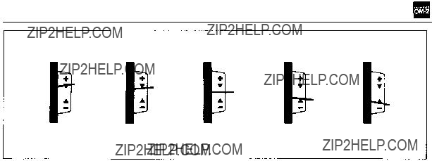
INTERCHANGEABLE FOCUSING SCREENS
The OM System interchangeable focusing screens
provide you with the ultimate in focusing versa-
tility. Optional screens are available to suit virtual- ly every
focusing screen:
a)Detach the camera lens from the camera body.
b)Use the special tool provided to push up on the release catch underneath the top ledge of the mirror box (see the photo above). This allows the screen and screen frame to drop down.
c)Remove the screen from inside the camera by gripping the tip of the screen with the tool as shown.
CAUTION: Although the above procedure can be
done with fingers, it is recommended that you
use the special tool supplied. Changing focusing
screens is a procedure to be exercised with great
care. Trying to change a screen with your fingers can result in fingerprints and costly damage to the surface of the screen, the prism, or the mirror. Should this occur, cleaning or repair MUST be handled by an authorized service center. Such
damage is not covered by the product warranty.
d)To install the screen, fit it into the frame and push the frame upward gently until it clicks into place. Gently shake the camera body to make sure the screen is held securely in place.
28

FLASH PHOTOGRAPHY WITH THE T32(orT20) ELECTRONIC FLASH 
Electronic Flash T32
Electronic Flash T20
T32 calculator panel (blank side for TTL "OTF" Auto flash)
The T32 and T20 are the world's first fully auto- matic electronic flash units. All their functions are controlled directly by the
tremely easy, yet highly accurate flash exposures.
(See pp. 61~69 for further information on flash units.)
29
Attach the Acces- sory Shoe 4 to the
Set the camera's se- lector lever to the "AUTO" position and switch on the T32 (or T20).
NOTE: Mounting the T32 (or T20) on the acces- sory shoe automatically completes the "X" syn- chro circuit. It is not necessary to set the X and FP flash selector to "X".
 A red lamp lights in the viewfinder when the T32 (or T20) capacitor is charged ready for shooting.
Set the aperture ring to the f/stop you require, focus on the subject and release the shutter.
NOTE: All f/stops on the camera lens can be
used.
30

FLASH PHOTOGRAPHY WITH THE T32 (or T20) ELECTRONIC FLASH 
If the lamp flickers: correct flash exposure has been made.
If the lamp goes out:
tance is beyond the TTL AUTO working
range. Open up the lens stop or move in closer to the subject.
If the lamp stays lighted: correct exposure has been made by existing light, requiring no flash.
Light Blue
In case exposure must be achieved by flash illumi- nation, turn the aperture ring until the meter
needle points to 1/30 sec. or slower, and shoot.
NOTE: The
31
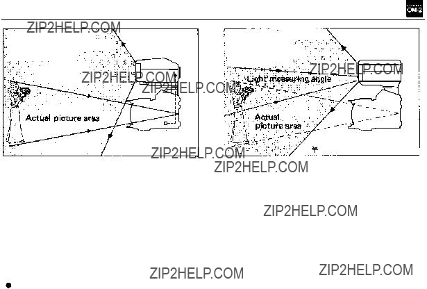
THE
COULDN'T BE SIMPLER AND MORE ACCURATE
Picture angle
= Light measuring angle
All required of the T32 (T20) is a flick of the on/ off switch. The rest is taken care by the  The dial settings required of conventional "auto" flash units ??? ASA film speed setting, aperture setting, flash mode switching, exposure compensation ??? are not needed with the T32 (T20).
 Unlike conventional auto flash units which re- gulate flash emission by an independent light sen- sor, the T32 (T20) utilizes the
in SBC light sensors, so that flash acceptance angle
always coincides with the picture angle of the camera lens.
The
instant the flash exposure has been completed.
Picture angle
Light measuring angle
eliminating camera shake. Correct exposure can be confirmed without taking your eye off the viewfinder.
 By the incorporation of an incorrect flash pre- vention system, the electronic flash will not fire if the shutter speed is faster than the synchroniz- ing range.
 Special techniques such as diffused lighting are made easy, obviating complicated compensa- tions and guesswork.
 Usable
32
BOUNCE FLASH
The T32 flash surface can be tilted upward through
an angle of 90??, providing easy bounce TTL Auto flash.
Point the flash surface at the ceiling so that
the subject is illuminated by soft reflected
light.
33

15??).
34

FLASH PHOTOGRAPHY WITH AN ELECTRONIC FLASH UNIT OTHER THAN THE
Attach the Accessory Shoe 4 to the
Mount the electronic flash on the accessory shoe.
If your electronic flash unit does not have a direct contact "hot shoe", connect its syn- chronizing cable to the camera flash socket.
Set the synchro terminal to "X" by aligning the red dot on the FP and X selector with the "X" indication alongside the flash socket.
NOTE: Mounting the electronic flash unit on the accessory shoe automatically completes the "X"
synchro circuit. However, there are some flash
units which do not fire unless the selector is set to "X".
[With Quick Auto 310]
The Quick Auto
combination cannot perform the TTL
("OTF") Auto flash. Use it in the Normal Auto or Manual flash mode.
Set the camera's selector lever to "MANUAL".
Set the ASA film speed on the flash unit.
Set the shutter speed ring to 1/60 sec. or slow- er.
Set the flash unit to the automatic or manual setting.
Set the desired F stop on the flash unit (in the case of auto mode), and then set the aperture ring to this F stop. In the case of manual mode, F stop can be determined by using the follow- ing formula:
35

FLASHBULB PHOTOGRAPHY
Plug the synchronizing cable leading from the flash unit into the camera flash socket, and then attach the flash unit to the camera.
Select the proper synchro setting from the table below according to the type of bulb be- ing used, and align the red dot on the X and FP flash selector with the "X" or "FP" in- dication alongside the flash socket.
CAUTION: With the
unit, the synchronizing cable must be used to
connect the unit and the camera.
 Select the proper shutter speed from the table
below, and set the shutter speed ring accord- ingly.
Determine the correct F stop for flash exposure by using the calculator dial, exposure chart or guide number formula. Set the aperture ring to this F stop.
 The table indicates proper synchronization speeds for most flash equipment.
36

MOTOR DRIVE PHOTOGRAPHY 
Motor Drive 1
The standard motor drive unit forms the heart of the Motor Drive Group. An extremely
"single" mode of operation, winding film at a high speed of 0.16 second per frame.
Remote Control Jack
Shutter Release
Lock Lever
M. 18V Control Grip 1
37

Attaching the Motor Drive 1
Remove the motor drive socket cap from the camera base plate.
Insert the motor drive guide pin into the guide pin hole on the camera base plate. Turn the clamping screw clockwise until the Motor Drive 1 is securely attached to the camera base plate.
Attaching the M. 18V Control Grip 1
Remove the M.18V Battery Holder 1, insert twelve 1.5V penlight (AA) size batteries into the battery holder, and
Align the red index line, and push the control
grip forward until it snaps into the front of the motor drive.
NOTE: A
the M. 1 5V
38

MOTOR DRIVE PHOTOGRAPHY 
Photography with the Motor Drive Units Using the M. 18V Control Grip 1
Unlock the shutter release lock lever on the Control Grip.
Turn the mode selector on the Control Grip to either "SINGLE" or "SEQUENCE". Set the mode selector to the "OFF" position when the Motor Drive 1 is not in use.
NOTE: In either mode, automatic exposure con-
trol is possible in the full range of shutter speeds,
and manual exposure is possible from 1 second to
1/1000 second.
Release the shutter.
NOTE: You may use either the shutter release on the Control Grip 1 or the shutter release on the Motor Drive 1 to trigger the shutter.
39
WINDER 2 OPERATION
Shutter Release
Remote Control Jack
Guide Pin
Winder 2
The unit provides the OM cameras with automatic film winding capability for
as sequential filming (max. 2.5 frames per second).
Mode Selector
40

WINDER 2 OPERATION 
Attaching the Winder 2
Remove the motor drive socket cap.
Pull up and rotate the mode selector to the
"OFF" position.
Remove the M. 6V Battery Holder 1 from in- side the winder, insert four 1.5V penlight (AA)
size batteries into the battery holder, and put it back into the compartment. Insert the guide pin into the guide pin hole on the camera base
plate. Turn the clamping screw clockwise until the Winder 2 is securely attached to the cam-
era base plate.
Taking the pictures
Pull up and rotate the mode selector to the "SINGLE" or "SEQUENCE" position.
Press the shutter release.
NOTE: The removed motor drive cap can be
stored in the socket cap storage positioned on the
underside of the battery holder compartment.
41

CARE AND STORAGE
General
Dust and moisture are harmful agents affecting your camera. Remove the camera from the case
and store it in a dry,
or similar volatile chemical materials to avoid
the possibility of damage to metal surfaces. When storing the camera for a long period of
time, remove the battery. Wipe battery surfaces with a dry cotton cloth before
the camera.
Avoid dropping or hitting the camera.
Never store the camera where temperatures ex-
ceed 50??C (122??F). When you use the camera in temperatures under
this, warm the camera before use. Protect against
excess moisture by using packs of silica gel or
other desiccant in the storage area.
After use near the ocean, wipe the camera sur-
faces clean with a soft cloth; never leave salt on the camera. (Salt may be airborne near the
ocean and collect on the camera even though it
has not been in direct contact with water.) Avoid excessive tightening when mounting on
a tripod.
42

Avoid areas exposed to corrosive chemicals, radios, TV sets, or magnets.
Have all repairs performed by an authorized OLYMPUS Service Center. You may send it
through the store where you bought your cam-
era or directly to an Olympus Service Center.
Parts
 Do not press the shutter release button at random.
 Do not touch any part that moves at high speed
such as the shutter, instant return mirror, dia- phragm, etc.
Avoid touching the surfaces of the lens. Clean only with an air blower, antistatic brush, or wipe
it lightly with a camel hair brush or lens tissue.
In EXTREME cases, use a clean, soft cotton
cloth moistened with denatured alcohol. NEV- ER rub the lens surfaces with your finger, cloth- ing, or other abrasive material.
If dust or fingerprints collect on the mirror,
focusing screen, or prism, take the camera to an authorized OLYMPUS Service Center. It needs
professional attention.
43

QUESTIONS & ANSWERS
Q:My camera is loaded with film. Why doesn't
the rewind knob rotate when I advance the film?
A:The film leader may not be inserted in the film
Q:Why can't I advance the film?
A:The shutter may be cocked and ready to fire. Try pressing the shutter release button. (See page 10.)
Or, the film may be fully exposed. Check the exposure counter. If you feel tension on the film advance lever, DO NOT FORCE IT. Re- wind the film. (See page 20.) Or the self- timer lever is not securely in its upright posi- tion, reset and release the
page 21.)
Q:Why won't the shutter release button move
when I press it?
A:The film advance lever may not have been
fully advanced. (See page 9.)
Q:I can't advance the film nor release the shut- ter, and the viewfinder is totally dark. Why?
A:The mirror is locked up because the batteries are depleted or the film was advanced in the middle of an automatic exposure. Press the selector lever to the "CHECK???RESET"posi- tion to unlock the mirror. (See page 8.) Two batteries should be replaced as a pair if they are depleted.
Q:Why won't the rewind crank turn when I try
to rewind the film?
A:The rewind release lever may not be rotated in the arrow direction until it aligns with the
Q:Why can't I set the ASA film speed I need?
A:At the most, 3 stops can be advanced in a single stroke of the dial. If you require more stops, lift up and rotate the outer collar of
the dial until it stops; then release the collar and reverse the collar and dial together until the white line is aligned with the black index on the pentaprism. Repeat this procedure until you reach the ASA speed you need. (See page 11.)
44

Q:What batteries should I use?
A:Use two 1.5V silver oxide batteries SR44 (Eveready
use 1.3V mercury batteries (though they
are the same size). (See page 7.)
Q:Why doesn't the battery chamber cap fit?
A: If you also own an
Q:When should I check the batteries?
A:(1) When new batteries are inserted. (2) After the camera hasn't been used for a long time. (3) Before beginning a prolonged period of use.
Q:Can film be properly exposed when the selec-
tor lever is in the "OFF" position?
A:The
haustion.
Q:Can I set the shutter speed ring to any posi-
tion to take pictures on AUTO mode?
A:Any position except "B".
Q:Why is the automatic exposure shutter speed
much longer than indicated by the meter in the viewfinder?
A:If film is not loaded, the shutter speed is much longer than that indicated. If it is necessary to obtain a correct reading with- out actually taking a picture, insert a waste, undeveloped film or the paper you find be- hind the camera back at the purchase of your
Q:Can I use the exposure compensation dial when the selector lever is set at the "MAN- UAL" position?
A:Yes. If the exposure compensation dial is set for an intentional over- or
45

Q:How can I remove dust from inside the view- finder?
A:After detaching the Focusing Screen, blow away any dust with an air blower. Never wipe the screen surface with cloth or paper.
(See page 28.) If this does not solve the pro- blem, send your camera to an authorized OLYMPUS Service Center.
Q:Is it normal for the microprism in the center of the viewfinder to "shimmer" and darken?
A:Yes, when a lens with a maximum aperture
smaller than F5.6 is mounted on the camera. It also happens with other lenses when the depth of field preview button is pressed.
Q:Why does the
A:The lever will stop without releasing the shut- ter if the film has not been fully advanced. Reset the
is fully advanced. The
page 21.)
Q:Can I operate the camera without the motor
drive socket cap in place?
A:No. Light will enter the camera body through
this hole, fogging the film. Also, dust and dirt may enter, causing a camera malfunc-
tion.
Q:Why doesn't my electronic flash unit fire when I release the shutter?
A:If the shutter speed is 1 /125 second or faster in conjunction with the electronic flash T32 or T20, the
system does not permit flashing. Confirm the shutter speed. (See page 31.)
Q: Why do I feel a small electrical shock when I touch the terminal contact of the accessory shoe?
A:This is normal when using a
46

THE MOST IMPORTANT FEATURE OF THE
Diagram of light path in conventional SLRs
Stray
Light
The instant the shutter has been released
(A memory device controls the shutter speed, based on the light reading taken before actual exposure.)
In the automatic mode, the
Diagram of light path in
Before shutter release
The instant the shutter has been released
Light Sensor Position
sors at the precise moment the film is being ex- posed. When sufficient light has reached the film, the electronic brain senses the information and instantly closes the shutter.
47

Shutter Speed at F1.2
Exposure range of
Exposure range of conventional
AE SLRs
Advantageous Points of
1.The
2.The sensors measure flash intensity as it builds up and cut off its light at the source when the correct exposure level is reached. (TTL Cen- tralized Control Flash)
3.Even during
be automatically exposed for up to 120 sec- onds at F1.2.
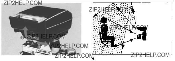
5.The Method excludes all possibilities of stray light leaking through the camera eyepiece and affecting the exposure reading.
6.The Method gives correct exposures even when the
posure for each frame individually.
4.The Method operates accurately in far dimmer light than other systems. ASA 100 film can
48
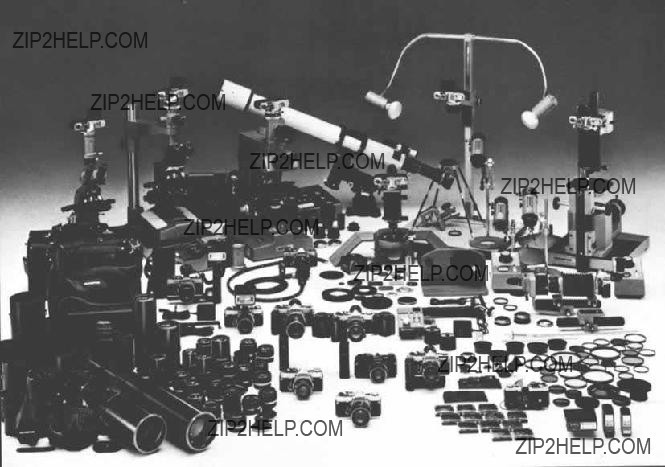
OM SYSTEM
The OM System is comprehensively arrayed to meet an
A
???Interchangeability of focusing screens.
???Adaptability to high speed motor drive pho- tography.
???A wide range of high quality system compo- nents, including interchangeable lenses.
???Compatibility of the camera body with an electronic flash unit allowing high technic flash photography with extreme ease and accuracy.
???Tough and reliable shutter, viewfinder, etc. that withstand harsh handling without fail- ing.
When these exacting conditions have been satis-
fied, an
controls an entire SLR comprehensive system. The
systematically organized under eight groups ??? In- terchangeable Lens, Finder, Flash, Motor Drive, Phototechnical, Macrophoto, Photomicro and Case.
50

ZUIKO INTERCHANGEABLE LENS GROUP
One of many advantages of the single lens reflex camera is the large variety of interchangeable lens-
es available. The Zuiko Interchangeable Lens Group (designed and manufactured by Olympus)
comprises 33 lenses. Zuiko lenses have always en- joyed a high reputation in photographic circles ??? the most modern design technology and employ- ment of newly developed optical glass have made possible a new series of innovative, high perform- ance lenses. These lenses have a host of special features including new construction that compen- sates for close focus aberrations, increased aper- ture ratio in the wide angle lenses, and reduction in telephoto lens size and weight. The OM Sys- tem adopts 49mm filters for most lenses from 21mm to 200mm. As part of the OM System design all the lenses now offer higher perform- ance in small configurations. Olympus has pro- duced lenses for microscopes for decades and the new Zuiko lenses benefit from this scientific experience. See the "OM System Zuiko Inter- changeable Lenses" manual for further in- formation.
51


TABLE OF INTERCHANGEABLE LENSES

MAX.
LENGTH
DIAMETER
82mm 102mm 59mm
42mm 62mm
43.5mm 60mm
31mm 59mm
48mm 60mm
31mm 59mm
43mm 60mm
31mm 59mm
42mm 60mm 33mm 59mm
58mm 68mm
47mm 65mm
39mm 60mm
31mm 59mm
40mm 60mm
74mm 67mm 63mm 196mm 70mm
48mm 60mm 48mm 50mm 80mm 61mm
73mm 60mm 124mrn 80mm 127mm 67mm 105mm 62mm
181mm 80mm 255mm 80mm
377mm 110mm
662mm 110mm
20mm 32mm
28mm 43mm
33mm 59mm 47mm 60mm
HOOD
49 72mm
72mm
55mm
49mm
55mm
49mm
49mm
49mm
55mm
51mm
49mm
57mm
51mm
51mm
60mm
49mm
49mm
Built in
57mm
FILTER
72mm
55mm
49mm
55mm
49mm
49mm
49mm
55mm
49mm
49mm
55mm
49mm
49mm
49mm
55mm
49mm
55mm
49mm
49mm
55mm
49mm
72mm
55mm
49mm
72mm
72mm
100mm
100mm
21mm
32mm
49mm
55mm
Compatible : The meter needle indi-
cates correct light read-
ings. In the combination
marked with *, micro- prism,
Compatible: The meter in the
cannot be used. On AUTO, the
shutter speeds.
(Specifications subject to change without notice.)
54

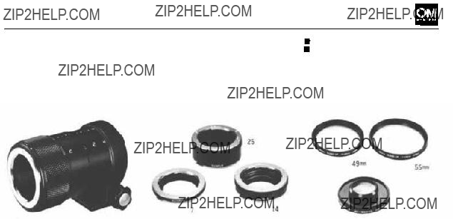
INTERCHANGEABLE LENS GROUP UNITS
 Lens Hoods
Lens hoods protect against ex- traneous light striking the lens and causing unwanted glare. Hoods for standard lenses are cover types and can be reversed to provide easy storage even when the camera is in the case. Five lens hoods are optionally available (see TABLE OF IN-
TERCHANGEABLE LENSES on pp.
Camera Body Cap
Rear Lens Cap
Front Lens Caps
(49mm, 55mm, 72mm and 100mm in diameter)
 Adapter Ring 49
  72mm
72mm
A lens hood/filter mount for the 18mm F3.5 lens.
 Filters
Filters are essential to the effec- tive rendition of photographic
subjects. In controlling contrast
and eliminating unwanted haze in black and white photography, the use of the correct filter often means the difference between a good photograph and a great one. In color, where the balancing of the light with the film emulsion is absolutely necessary for cor-
rect color, conversion and light
balancing filters are the only ef-
fective way of achieving the de-
sired results.
* Be careful not to use two filters simultaneously in order to avoid unintentional cut in the per- iphery of a photograph.
(See the table of various filters
on the opposite page.)
55

Application Name Color
Description
Similar to UV filter. Eliminates ultraviolet rays. Re- duces haze and bluish tones in daylight photography. Effective with color film only. May be used at all times
to protect the lens.
Eliminates undesirable ultraviolet rays which cause dull, flat pictures. Renders subject in clear detailed brilliance. May be used at all times to protect the lens.
Reduces the quantity of light entering the lens to 1/2 or 1/4 of the original intensity. For use in extremely bright conditions when you wish to maintain a wide aperture.
Enables you to take pictures through glass or water without reflections. Will darken the sky in
Accentuates contrast, darkens blue skies. Very effective
in daylight scenes where the sky is part of subject mat- ter. Heightens the effect of white clouds. Usefull in copying documents where line copy is blue or black on light background.
Absorbs a wider range of wavelengths from UV to dark green than the Y2. Makes a superb rendition of the tex- ture of outdoor subjects, and indoors. It brings but
detail in objects yellow, brown. Used with infrared film.
Used as contrast filter to create darkened sky or in copy-
ing. Also used to penetrate haze in landscape photo- graphy for stronger contrast than an O2 filter. Used with infrared film.
For use when taking color pictures in cloudy or rainy weather. Reduces bluish tone.
Designed for use when taking color pictures in early
morning or late evening hours when red rays are pre- dominant.
Diameter
49mm 55mm 72mm 100mm
56

FINDER GROUP
The viewfinder is one of the most important fea- tures of a single lens reflex camera. Since every photographic subject is turned into a visual image by means of the finder, a finder that is dark or difficult to look through is an obstacle to good photography. However enriched an SLR camera is with a wide range of interchangeable lenses, the SLR cannot be expected to fulfill its essential func- tion without the provision for changing of focus- ing screens. The
57

FINDER GROUP UNITS
 Varimagni Finder
This unique and exclusive unit for the OM System combines the two functions of angle finder and magnifier, incorporating 9 lens elements and a reflector. It fits over the camera's eyepiece,
and can be adjusted for indi-
vidual eyesight. Its eyepiece tube
is rotatable through 360??, for
use in low level and 90?? angled shots. The
 Eyecup 1
Attached by sliding over the OM Body eyepiece. Its rubber hood prevents stray light from entering through the eyepiece, an essen- tial requirement in light measur- ing. The Eyecup 1 is provided with a slot for Dioptric Correc- tion Lenses.
 Eyecoupler
Connects the Varimagni Finder to the OM Body for photomicro- micrography. It also ensures full
coverage of the bright viewfinder
field for use of the Eyecup 1 in conjunction with the Motor Drive 250 Film Back.
 Focusing Screen 1
Interchangeable Focusing Screens are often thought of as a luxury feature in 35mm photography. Yet the Standard Focusing
Screen
58
or difficult to use, and, in some circumstances it is quite unsatis- factory. With
prism becomes excessively dark.
With the high magnifications of macrophotography and photo- micrography, it is impossible to focus.
The feature of each Focusing Screen is listed on pp.
 Dioptric Correction Lens 1
Available in 8 diopter correc- tions: + 2, +1,0 (for hypermetro- pia);

FINDER GROUP UNITS
type
(for most lenses)
type
(for standard & telephoto lenses)
Split
(for most lenses)
All matte type
(for most lenses)
Microprism
field type
(forwideangle& standard lenses)
field type
(for standard & telephoto lenses)
(for super telephoto lenses)
Standard type, suitable for general photography. Fast and accurate
focusing is done on the central microprism spot as well as on the sur- rounding matte area. When a lens with a maximum speed of F5.6 or slower is used, the microprism darkens and focusing must be made on the matte area. The meter needle indicates proper exposures.
Suitable for general photography in conjunction with a standard or telephoto lens. Focusing is done on the microprism spot as well as on the matte area. When a lens with a maximum speed of F8 or slower is used, the microprism spot darkens. The meter needle indicates prop- er exposures.
Suitable for general photography ensuring critical focusing, and ideal
for photographers who prefer the
Suitable for general photography and ideal for photographers who prefer a view field free from microprism or split prism and for those who are accustomed to focus using matte area. Also suitable for super telephoto photography and
proper exposures.
This transparent screen provides an exceptionally bright finder image. Highly suitable for snapshots using wide angle lenses. The lack of matte surface means
This screen provides an extremely bright finder image. Focusing is done on the microprism spot. The lack of matte surface means depth
Developed primarily for use with super telephoto lenses, this clear field screen provides an extremely bright finder image. The micro-
prism spot remains bright even with a lens whose maximum speed is
11. The lack of matte surface means
59
60

FLASH PHOTO GROUP
Flash is your own private "sun" when you take pictures at night, indoors, or outdoors for day- light
At present the OM System Flashphoto Group ren- ders choice of 5 different flash units, including the Electronic Flash T32 and T20. TheT32 offers high performance ??? a maximum ASA 100 guide
number of 32 (in meters) or 104 (in feet) with an
angle that virtually covers the picture area of a 24mm
ly compact and features a maximum ASA 100 guide number of 20 (in meters) or 66 (in feet)
with an angle that covers the picture area of a 35mm wide angle lens. The T32 (or T20), when
used with the
ly automatic electronic flash unit. Even the dial settings (auto/manual switching, aperture setting and ASA film speed setting) required of conven- tional "auto" flash units are unnecessary. By re- versing the back plate of the flash unit, it can be used as a normal auto/manual flash unit for use with the
and GN32 (GN 20 with T20).
61


FLASH PHOTOGRAPHY SYSTEM CHART
63

FLASH PHOTO GROUP UNITS
 Electronic Flash T32
The T32 is the center of the
modular OM Flashphoto system.
Used alone on the camera, the
allows the flash surface to be tilted 90?? up and 15?? down. This angle range can be further ex- tended when the T32 is slipped into the Power Bounce Grip 2.
Operates on four 1.5V AA (self- contained) or C batteries (inside bounce grip) including
70mm (4.1"x3.2"x 2.8"),320g.
(11.3 oz.) less batteries.
 Electronic Flash T20
Extremely compact and light-
weight. Like its sister unit T32,
the T20 is an
ble of TTL Auto, normal Auto and manual flash and provides the flash charge/correct exposure indication in the OM camera viewfinder (but with no built- in bounce mechanism). Operates
on two 1.5V AA
(3" x 2.7" x 2.2"), 160g. (5.6
oz.) less batteries.
64
 T10 Ring Flash 1
Designed principally for use with
the OM System macro lenses, this unit provides full and even flash
illumination at working distances
far closer than possible with other flash units. Operates in
conjunction with the T Power
Control 1.
 Ring Cross Filter POL
A

FLASH PHOTO GROUP UNITS
 TTL Centralized Control Flash by T32 (T20)/
The T32 (T20) utilizes the
On conventional auto flash units, the auto sensor is built into the flash unit. The sensor regulates flash emission independently of the camera. While normal auto flash units can also give a correct ex- posure, they are far less versatile and convenient in use. Their drawbacks include:
 The need to set film speed and lens aperture on both the camera and the flash unit, which leads to exposure errors caused by mistaken film speed and/or aperture alignment.
  With the T32 (T20)/
Restrictions on the
through the camera lens.
 Inability to change the light measuring angle of the sensor according to the taking angle of the chosen lens.
  With the T32
angle of the taking lens.
Restricted
with extension tubes, etc.  With the T32 (T20)/
65

 T Power Control 1
A compact power unit for the
T10 Ring Flash which mounts via accessary shoe to the top of the OM body. Offers TTL Direct "OTF" auto operation or manual flash (GN 10andGN 4, ASA 100 in meters). Powered by 4 AA size batteries or optional AC Adapter
3.
Calculator panel for 50mm lens Calculator Panel for 1:1
Macro 80mm lens  Calculator Panel for Macro
135mm lens
Fitted on to the back of the
T10 Power Control 1 to provide
 TTL Auto Multi Connector
Allows multiple flash units (T32s or T20s) to be combined with the camera
 TTL Auto Connector T20
Allows the T20 to perform off- camera flash via the TTL Auto
Cord T when the Power Bounce Grip 2 is not used (i.e.,
66

FLASH PHOTO GROUP UNITS
 TTL Auto Cords T 0.3m,
0.6m, 2m, 5m
Links the T32 and T20 elec- tronic flash units with the OM body when used separate from the camera. In addition to the 0.6 meter spiral cord, 0.3m, 2m and 5m cords are available.
 M. Grip Cord
Connects the remote shutter re- lease on the Power Bounce Grip 2 for operation with the Motor Drive 1 or Winder 2 units.
 Power Bounce Grip 2
An auxiliary power unit which converts the T32 and T20 elec- tronic flash units into
 Zoom Adapter T32
Offers concentrated flash beam
with the T32 Electronic Flash sufficient for telephoto lenses 135mm and longer.
67
for reducing the light intensity
without affecting color and contrast.
 Electronic Flash AC Adapters
Enables operation of the T10
Ring Flash 1 and its modelling
lamp on AC current.
 Electronic Flash AC
Adapter 2
Plugged into an AC wall outlet,
this unit supplies a virtually un-
limited number of economical
flashes with the T32 (or T20).
68

FLASH PHOTO GROUP UNITS
 Lens Pouches 150/100
The Lens Pouch 150 (100) is also suitable for carrying the T32 (T20) electronic flash unit, on its own.
 Compartment Case S
A hard shoulder case with two adjustable partitions to accom- modate the OM Body, T32 (or T20), bounce grip and bracket.
 OLYMPUS PS200/PS200
Quick
These manual flash units are for use with cameras with a hot shoe mount, have the guide number
of 14 (in meters) or 45 (in feet)
at ASA 100 and a constant flash duration of 1/1000 sec. and de- liver approx. 200 flashes. The
PS200 operates on two 1.5V AA batteries (recycling time ap- prox. 7 sec.) and the PS200 Quick on four AA batteries (2~
3 sec.). PS200: 31 x 55 x 64mm
(1.2" x 2.2" x 2.5"), 75g. (2.6 oz.) less batteries. PS200 Quick:
32 x 73 x 71mm (1.3" x 2.9" x
2,8"), 95g. (3.4 oz.) less bat- teries.
69

MOTOR DRIVE GROUP
The attraction of the motor drive is its ability to capture fleeting phenomena which exceed the capabilities of human response. Tailored perfect- ly to match the OM camera body, each unit of the Motor Drive Group has been reduced in size to enhance its maneuverability and ease of opera- tion.
The basic motor drive package (Motor Drive 1 + M. 18V Control Grip 1,or Motor Drive 1 + M. 15V
The many uses of the units of the Motor Drive Group in conjunction with other units of the Macrophoto, Photomicro and Flash Photo Groups permit even a greater range of photographic possi- bilities with the motor drive than originally imagined.
71

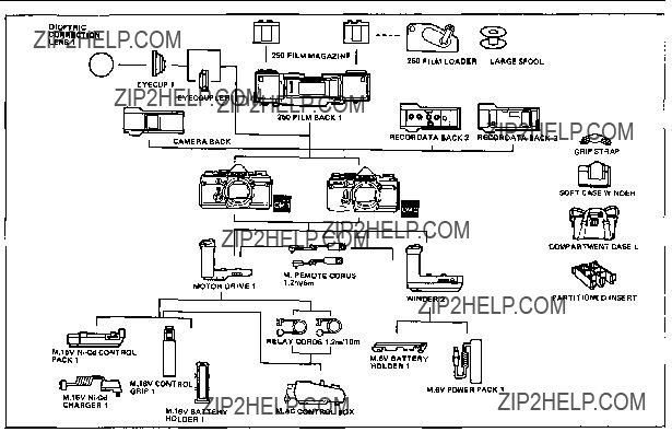
CHART OF MOTOR DRIVE GROUP
73

MOTOR DRIVE GROUP UNITS
 Winder 2 (with M. 6V Battery
Holder 1)
Attached directly to the camera
base, the Winder 2 performs single frame as well as sequential
shooting (2.5 fps).
Operating on 4
ble of powering approx. 50 rolls
of
Size: 130 X 64 X 98mm (5.12 X 2.52 X 3.86 in.). Weight: 290g (10.2 oz.) (less batteries).
 M. 6V Power Pack 1
This pocketable power unit (4 AA batteries) connects to the
 Motor Drive 1
The basic motor drive unit that forms the foundation of the group. Attached directly to the camera base together with the
power supply. It is capable of
single frame shooting and se- quential filming of 5 frames per second.
Size: 116 X 82 X 66mm (4.57 X 3.23 X 2.59 in.). Weight: 210g (7.4 oz.).
Winder 2 via a 1.2m cord. Warm- ed by photographer's body heat, permits operation in tempera- tures as low
74
 M.18V Control Grip 1 (with
M. 18V Battery Holder 1)
A power supply that accepts 12 AA batteries. Can be attached
quickly to the Motor Drive 1.
Size: 136 X 87 X 32mm. Weight:
160g (less batteries).
 M. 15V
This is a
Size: 129 X 35 X 67mm. Weight: 260g.

MOTOR DRIVE GROUP UNITS
 M.AC Control Box
AC transformer for use with household current. Incorporates a selector switch between single- frame and sequential exposure operation, a terminal for the re- lay cord and an intervalomejer.
 M. 15V
This AC adapter is necessary to charge the M. 15V
 250 Film Back 1;250 Film
Magazine
Used with the Motor Drive 1 or Winder 2 for roll films up to 250 exposures. Two Magazines are necessary.
 Relay Cords 1.2m and 10m
Extension cords between the
Motor Drive 1 and the power source for remote control.
 250 Film Loader
Used in the darkroom for load- ing the 250 Film Magazine from 33m (100 ft.) bulk film rolls.
 Compartment Case L
 Partitioned Insert
Can be slung over the shoulder or carried by hand. If used with an optionally available partition- ed insert, the Case L accommo-
dates motor drive equipment.
 M. Remote Cords 1.2m/5m
To be fitted into the remote control jack of the Motor Drive
1 and Winder.
75

MACROPHOTOGRAPHY GROUP
Due to recent advances in macrophotography, it has become possible to discover patterns and colors of unsuspected beauty in the minutiae of nature. A fast growing number of scientists and amateurs are taking the opportunity to explore the living world around them to new depths.
The Macrophotography Group of the OM System provides all the tools necessary to capture this world of perfection on film, offering a complete
range of convenient high performance accessories
designed for specialists in the various fields of macrophotography. Starting from
about 10x, and heightens the value of the OM
System in pursuit of perfection on film.
76

CHART OF MACROPHOTOGRAPHY GROUP
77
MACROPHOTOGRAPHY GROUP UNITS
 Telescopic Auto Tube
Featuring automatic diaphragm
linkage and offering continuous
extension from
making macrophoto work as
easy as snapshots. Subject area
extends to 72mm x 48mm (2.8" x 1.9") when used in conjunc- tion with the 135mm macro lens, and runs all the way from 72mm x 48mm (2.8" x 1.9") to 36mm x 24mm (1.4" x 0.9") in conjunction with the 1 : 1 Macro 80mm lens.
 Auto Extension Tubes 7, 14
and 25
Each of these bayonet mount tubes fits between the OM Body and the lens, featuring automatic diaphragm linkage. Available in extensions of 7mm, 14mm and 25mm, and can be used in 7
different combinations in total
to give a variety of magnifica-
tions. Another set of these
extension tubes of the sam sizes
without the automatic dia-
phragm linkage is also available.
For magnifications 0.5x and higher however, the 50mm macro tenses are recommended for superior resolution.
78
These attachment lenses thread directly over the standard lenses or 50mm macro lens, permit- ting magnification increase with- out affecting automatic dia-
phragm action. The
49mm is used with the 50mm F1.8 and F1.4 standard and 50mm macro lenses; the close- up lens 55mm with the 55mm F1.2 standard lens.
 Close-up
For use with the MC 1 : 1 Macro 80mm lens to extend magnifica-
tions with the Telescopic Auto
Tube from 1x to 2x.

 Auto Bellows
A basic unit extending your
of various OM lenses at the mo-
ment of exposure in conjunc-
tion with the double cable re- lease.
 Objective Lens Mount PM-
MTob
This objective mount enables you to mount the Zuiko Macro 20mm and 38mm to the Auto Bellows.
 Focusing Rail
This is used with the Focusing Stage and connects to a tripod, the Copy Stand, or Macrophoto Stand B Adapter, so that the camera can be smoothly moved
along the Rail, allowing you to
focus and compose as desired.
 Focusing Stage
Allows you to mount the cam- era body on the Focusing Rail or Auto Bellows. When used with the Rail, you can change the camera position for fast and smooth focusing and composing.
 Slide Copier
For use in conjunction with the Auto Bellows to produce dupli- cates from
sult with the Slide Copier.
 Roll Film Stage
Attached to the Slide Copier to hold long roll films for duplica- tion.
79
 Power Bounce Grip 2
Converts the T32 (or T20) into a grip type electronic flash unit. Consists of a bracket section and a grip section which contains 4 C batteries to provide a power- ful supplementary power source.
The bounce head can be angled 90?? up, 20?? down, 60?? right and 240?? left allowing free choice of bounce and
 TTL Auto Cord T 0.3m, 0.6m,
2m, 5m
Used for
ferent lengths.
 M. Grip Cord
Connects the Motor Drive 1 (or Winder) with the shutter release incorporated in the bounce grip for comfortable
flash photography.
 Electronic Flash AC Adapters
Enables operation of the T10 Ring Flash 1 and its modelling lamp on AC current.
 6V Power Pack 2
An auxiliary power source unit for the modelling lamp of the T10 Ring Flash or winder units. Powered by four D size batteries.
 Electronic Flash AC Adapter 2
80

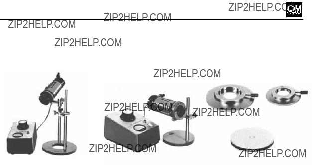
MACROPHOTOGRAPHY GROUP UNITS
 Macrophoto Stand
A rugged stand specially design-
ed for
(black at back) for incident light, and a pair of stage clips.
 Macrophoto Stand B Adapter
For use with the Macrophoto Stand, to support the Auto Bel- lows or Focusing Rail on the
Stand.
 Macrophoto Stand Extension
Bar
Extends the height of the Macro- photo Stand. Length: 7.5cm (2.95").
 Trans-llluminator
Indispensable for holding the
Macrophoto Stand
When used with the Lieberkuhn Reflector, it is convenient to re- place the reflector mirror with the Centering Mirror
 Double Cable Release
Attached to the Auto Bellows and camera shutter release but- ton, to activate them simultane- ously.
 Cable Release
 Copy Stand
A standard type stand, 48 x 44
cm, for general
 Handy Copy Stand
A
 Lighting Set
Complete with two units, each consisting of a base and light
arm. Max. intensity: 500W.
81

This pair of illuminators offers vertical illumination essential to macrophotography. The height of the illuminator is adjustable on the tall pillar, suitable to over- stage or substage illumination. When used with the
nator Base
Eight filters are available in vari- ous sizes, including color, black and white, neutral density, etc. for transparent or translucent subjects.
 Trans-llluminator
This unit is a universal type trans- illuminator for use with the X- DE
A 6V, 30W bulb is
condenser travels 18mm by rack and pinion for converging, di- verging and parallel adjustments
of light. Complete with trans- former and square filter 60 x 45C. Provided with a filter hold-
er for attachment of various
OLYMPUS filters, round and square.
 Lieberkuhn Reflector PM-
LM38
 Lieberkuhn Reflector PM-
LM20
These reflectors are available for use with the 20mm and 38mm
Macro Lenses. When used with
the LSD
tion and lack of shadows.
 Centering Mirror
For use with these
82
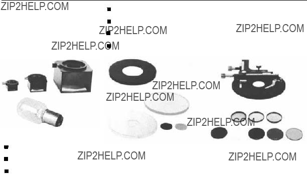
MACROPHOTOGRAPHY GROUP UNITS
 Incident Illuminator Mirror
Housings
EL38and
These units are used with OLYMPUS Macro Lenses in con- junction with the
objects with incident light. They are effective when shadowless pictures are desired.
Spare Bulb 6V 5A
(for
Spare Bulb 6V 5A
(for
Adapter
Accepts the photosensitive probe
of the
Auto Bellows.
Stage Glasses (Clear, frosted &
black)
Stage Plate 45 (metal disc,
black)
Stage Plate 28 (metal disc,
black)
Glass Shade Stage Plate
Supplied with two stage inserts;
compatible with the Lieberkuhn Reflector. The center port ac-
cepts the stage insert on which a subject is placed.
 Mechanical Stage FM
This stage is used to mount sub-
jects on the 28mm stage plate.
The subject travels vertically and
horizontally by precise adjust- ments with a vernier.
 Filters
Round filters are used with the
filters used with the LSD only. They are available for color tem-
perature compensation, mono-
chromatic, neutral density, diffu-
sion, heat absorbing and inter-
ference filtration.
83

PHOTOTECHNICAL GROUP
As a leading manufacturer of optical instruments
in various fields of modern life, OLYMPUS pro- vided the OM System with a wide variety of Photo- technical units, many of which can be used to successfully document your valuable achievements in photographs. This group includes a microscope adapter for use with an operation microscope, an astroscope adapter to explore the mysteries of space and stars in conjunction with a telescope, etc., mostly capable of attaching on the OM body. Other outstanding advantages of this group are the Recordata Backs 3 and 2 that are interchange- able with the OM standard camera back. Once in
place, the No. 3 Back automatically records the date
minute) in the lower right hand section of your
picture (camera held in the horizontal position) simultaneously with the shutter release. Externally, data can be displayed on the liquid crystal panel. Meanwhile, the No. 2 Back imprints numerical and alphabetical symbols in
For Olympus Pen F and FT enthusiasts, a mount
adapter is also available for connection of these cameras to the OM System interchangeable lenses and other unit
84


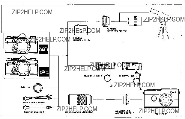
CHART OF PHOTOTECHNICAL GROUP
87
PHOTOTECHNICAL GROUP UNITS
 Recordata Back 3
This unit replaces the standard camera back to automatically record the date
 Recordata Back 2
The Back fits on the OM body and imprints data in the lower right corner of the picture. The data comprises numerical and al-
phabetical symbols for year,
month, day or other information in 4 dial coding. Can be used for

Adapter
Permits astrophotography by the OM Body attached to tele- scope by means of the 36.5mm diam., pitch 1mm and pitch 0.75mm threads. It enables di- rect objective photography and high magnification photography through the telescope eyepiece.
highspeed sequence photography with the Motor Drive or Winder units, and flash photography. Imprinting can be prevented, if
required, by simply setting the
selector switch OFF.
88
 OM-Mount
for Pen F
Connects the OLYMPUS PEN
F, FT and FV cameras to the
OM System Interchangeable
Lenses and other units.
 Double Cable Release
Used with the Auto Bellows.
 Cable Release

PHOTOMICROGRAPHY GROUP
When the photographic magnification desired ex- ceeds 10x, it becomes more difficult for the macro- photographic equipment alone to obtain excellent pictures. A sophisticated array of photomicro- graphy accessories with a microscope as the cen- tral figure is required. The exciting vision of look- ing at the microscopic world through a microscope can be recorded by the
OLYMPUS has an outstanding reputation for manufacturing precision microscopes used by scientists throughout the world. Naturally, the OM System includes a variety of microscope adapters, rugged stands, a special shutter to pre- vent vibration at high magnification, and an auto- matic exposure mechanism which solves the dif- ficult problem of microscope exposures.
The Photomicrography Group is designed to ex- pand the photomicrographic world not only into the scientific realm, but also into the creative sphere, so that the photographer's achievements under the microscope can be easily and accurately recorded with his
89
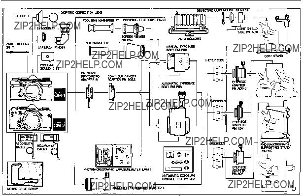
CHART OF PHOTOMICROGRAPHY GROUP
91
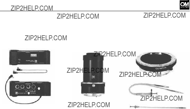
PHOTOMICROGRAPHY GROUP UNITS
 OM-Mount
Adapter L
Connects the OM Body to the microscope for low power mag- nification.

Adapter H
Connects the OM Body to the Photomicrographic System PM- 10, automatic or manual, or Macrophotographic Unit PMT- 35 for high power magnification.
 35mm SLR Camera Adapter
Used with
micro Adapter H to attach the
OM Body to the
PBM (see page 93).
 Photomicrographic Support-
ing Stand
This unit is a massive stand to virtually end the major cause of lost photomicrographs at high magnification due to vibration. Supports the entire camera weight, isolating it from the
microscope.
92
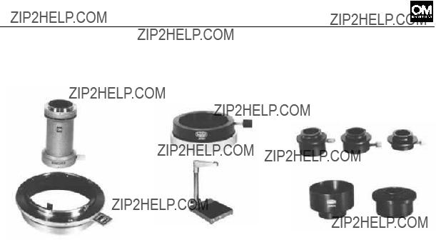
 Eyepiece Adapter
Used to connect a microscope to the
Adapter L. Each Adapter desig- nates OLYMPUS microscope eyepieces, as follows;
photo eyepieces.
 Light Shield Tube
Designed for use with the Auto Bellows and Objective Lens Mount

PHOTOMICROGRAPHY GROUP UNITS
System
Consists of 17 units, including
the
 Automatic Exposure Body
Automatically determines ac- curate exposure time.
 Automatic Exposure Control
Box
Used with the Automatic Expo- sure Body
 Manual Photomicrographic
System
This is a popular manual version of the
 Manual Exposure Body
 Photomicrographic Exposure
Meter
The
 5X Magnifier
For use with the Screen Viewer for magnifying any part of the subject area and focusing ac- curately.
 Focusing Telescope
For use with objectives 4x and up in conjunction with the Auto- matic or Manual Exposure Body.
 Focusing Magnifier FT
Used to magnify the image ob- tained by the Focusing Tele- scope.
93

CHART OF PHOTOGRAPHIC RANGES
PROFESSIONAL METHODS
COMPOSITE METHODS
94
GROUPS
ZUIKO
INTERCHANGEABLE
LENS GROUP
MACROPHOTOGRAPHY
GROUP
PHOTOMICROGRAPHY
GROUP
MACROPHOTOGRAPHY
GROUP

The Case Group includes a large variety of cases that the OM Body and other components fit properly.
Compartment cases are specially made of tough synthetic leather, designed to perfectly accom- modate camera bodies, lenses, motor drive, electronic flash
units, etc. The adjustable parti-
tions can be rearranged in the case to suit the photographer's individual requirements. Soft,
hard and
OM Body and standard lenses, with a choice of carrying straps.
Hard Case for OM Body
with F1.8 or F1.4
Hard Case for OM Body
with F1.2
Accommodates the OM Body with respective standard lens.

 Lens Pouch 100
Made of fine leather to contain a single 100mm lens or smaller lens or Electronic Flash T20.
Lens Pouch 150
Lens Pouch 200
A fine leather container for a
Soft Case for OM Body with F1.8 or F1.4
Accommodates the OM Body with F1.8 or F1.4 50mm lens.
 Soft Case for OM Body with F1.2
200mm telephoto lens, zoom lens, or smaller. Also holds the main body of Electronic Flash T32.
 Lens Pouch 300
Accommodates 300mm and 180 mm telephoto lenses.
 Various Shoulder Straps
95

 Compartment Case S
A hard shoulder case with two adjustable partitions. Holds OM
Body with two interchangeable
lenses and filters, or with Elec- tronic Flash T32 and Bounce Grip.
 Camera Holder for Case M
Besides the camera holder pro- vided with the Case M, one more camera holder is attacha- ble on the right or left wall of the case as preferred. These holders can hold two camera bodies simultaneously.
 Compartment Case M
A soft shoulder case with parti-
tions and two pockets. Holds
OM Body, three interchangeable lenses and various auxiliary equipment including electronic flash. It also accommodates clothing and toiletry for travel- ling, in addition to photographic
equipment, permitting camera and lenses to be taken out freely. Removable partitions are pro- vided to hold cameras and lenses in position safely without their individual cases, permitting quick lens changing on the cam-
era inside the case.
 Compartment Case L
A hard shoulder or
 Partitioned Insert
When inserted into the Compart- ment Case L, this unit supports the assembly of the Motor Drive Units. The 250 Film Back 1 and interchangeable lenses can be stored together with the OM Body.
96

CHART OF CASE GROUP
97

MAIN SPECIFICATIONS
System: OLYMPUS OM System.
Camera type: 35mm Single Lens Reflex with auto- matic exposure control electronic focal plane
shutter.
Film format: 24mm x 36mm.
Lens mount: OLYMPUS OM Mount, bayonet
type; rotation angle 70??, flange back focus distance 46mm.
Shutter: Focal plane shutter, automatic exposure
control from 120 seconds to 1 /1,000 second
(ASA 100, F1.2, at normal temperature and humidity). Manual exposure: B,
sec., ring mounted control.
Synchro:
X contact)
Automatic exposure control:
type. TTL Direct
ing System. Measuring range:
Exposure range: Shutter speeds from 120 sec. to
1/1,000 sec, (at normal temperatures and humidities). Light sensors: 2 SBC sensors.
Large exposure compensation dial: ??2EV
(within the ASA film speed range). Automatic flash exposure: Direct contacts for TTL Auto Flash (full automatic flash with T32, T20 or T10 electronic flash).
Manual exposure: TTL type. Measuring system:
Full aperture
uring range:
F1.2 standard lens). Light sensors: 2 CdS sen- sors.
and rotating film speed dial.
Auto/Manual selection: By selector lever.
Power source: Two 1.5V silver oxide batteries SR44 (Eveready
Battery check:
emitting diode) indicates full voltage, deplet-
ed charge, and exhaustion of batteries. Shut- ter lock to limit drainage.
Mirror unlock: Mirror
simultaneously with battery check.
Viewfinder: Pentaprism type
Focusing screens: Wide selection of interchange- able screens.
Supplied with Focusing Screen
Finder
Viewfinder magnification: 0.92X at infinity with
50mm- lens.
Apparent field of view: Vertical 23??30', horizon- tal 35??.
Indicators in viewfinder:
98

MAIN SPECIFICATIONS
(with
Reflex mirror: Oversize, quick return type (with- out
Film loading: OLYMPUS easy loading.
Manual film advance: Lever type with 150?? angle for one long or several short strokes,
vance angle 30??,
Motor drive advance: With Motor Drive 1 unit at- tached, single frame and continuous advance
at speed of
normal temperature and humidity).
Exposure counter: Progressive type with auto- matic reset.
Film rewind: Crank type, with rewind release lever
setting, automatic return.
180?? maximum angle; can be stopped and re- set after actuation.
Camera back: Removable hinge type, with memo
holder.
Interchangeable with Recordata Backs 2, 3
and 250 Film Back 1.
Hot shoe socket: OLYMPUS special Accessory. Shoe 4 supplied.
Dimensions and weights:
Body only: 136 x 83 x 50mm
(5.35" x 3.27" x 1.97") 520g (18.3 oz)
With F1.8 lens: 136 x 83 x 81mm
(5.35" x 3.27" x 3.19") 690g (24.3 oz)
With F1.4 lens: 136 x 83 x 89mm
(5.35" x 3.27" x 3.50") 750g (26.5 oz)
With F1.2 lens: 136 x 83 x 97mm
(5.35" x 3.27" x 3.82") 830g (29.3 oz)
99
OLYMPUS OPTICAL CO.,LTD.
OLYMPUS CORPORATION
Crossways Park, Woodbury, New York 11797, U.S.A. Tel.
OLYMPUS OPTICAL CO.(EUROPA) GMBH
2 Hamburg 1, Steindamm 105, West Germany. Tel:
OLYMPUS OPTICAL CO. (U.K.) LTD.
PRINTED IN JAPAN IEOM2 ?? 0800 ??? 15MS