Oakley Sound Systems

5U Oakley Modular Series

VCO Controller

1U wide oscillator master module

User Manual

V0.0.04 Preliminary Version

More Information to follow

Tony Allgood B.Eng

Oakley Sound Systems

CARLISLE

United Kingdom

The suggested panel for fitting to an Oakley modular system with the Oakley CV/gate buss. The twin keyboard control voltage (KCV) signals that this module generates are connected to the VCOs behind the front panel. If you do not have the facility for this you can make two of the front panel sockets carry the two KCV signals instead.

2

Introduction

This is the User Manual for the issue 1 VCO Controller 5U module from Oakley Sound.

This document contains a basic summary of its operation, how our Oakley Buss works, a guide to the front panel controls, how to connect it to your modules and finally calibration procedures.

For the Builder's Guide, which includes the parts list, schematic description and testing advice, please visit the project webpage at:

http://www.oakleysound/cv-cont.htm

For general information regarding where to get parts and suggested part numbers please see our useful Parts Guide at the project webpage or http://www.oakleysound.com/parts.pdf.

For general information on how to build our modules, including circuit board population, mounting front panel components and making up board interconnects please see our Construction Guide at the project webpage or http://www.oakleysound.com/construct.pdf.

The 5U VCO Controller Module

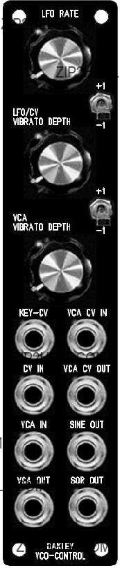
The Oakley VCO Controller is a 1U wide module designed to function as a master controller for two or more VCOs.

The basic premise of this module is to make it easy to control multiple oscillators. Quite often you will require simple vibrato of two or more VCOs. Normally this is done by patching one LFO (low frequency oscillator) to your VCOs via a multiple. This uses up a minimum of three patch leads for two VCOs and the vibrato depth needs to be set individually on each VCO.

With this module the internal sine wave LFO is added directly to the VCO's control buss, or by using two of the output sockets. One pot controls the depth of the LFO for both or more VCOs. The LFO may be overridden by inserting a jack into the CV IN socket on the module thus allowing other CVs to control multiple VCOs simply.

The VCO Controller also features an inbuilt VCA (voltage controlled amplifier) module. This allows the internal LFO, or any external CV, to be controlled by another CV. This CV may be aftertouch or modulation wheel outputs from your midi-CV interface. Thus, vibrato depth can be controlled with your keyboard or keyboard's wheel or lever. Only one patch lead is required to add touch sensitive or wheel controlled vibrato to your patches ??? normally this would require a minimum of 2U of rack space, a multiple, and a whole bunch of patch leads.

The VCA within this module can also be used separately as a ordinary VCA should you not wish to use the other features in the module at any time.

3

Also available are two octave switches. These affect the two keyboard control voltage (KCV) outputs of the module individually. This each VCO, or VCO bank, can be raised or lowered by one octave at a flick of a switch. Each KCV output uses a low impedance cable driver to ensure no droops with long signal runs and multiple loading.

Although this module was designed to work with the Oakley buss, which pipes around KCV and gate signals around your modular, the input and output sockets on this module can be assigned different purposes so as to suit individual requirements.

VCA control input is optionally low pass filtered so as to reduce stepping artefacts from midi generated CVs. This low pass filtered output is available via the VCA CV OUT socket so you can use it to control other modules.

The internal LFO outputs are available individually from the front panel as both sine wave (+/- 5V) and square wave (+5V, 0V).

More about the Oakley Buss and Module Normalisation

The Oakley buss is a three way connector found on various modules. Pin 1 carries the keyboard CV (note control) and pin 3 carries gate (note on or off). The VCO Controller module taps into the Oakley buss and creates two new busses for each VCO bank. It also has a buss through feature for easy wiring

The word buss is perhaps a little grand for something that has just two control lines and a single ground. However, it still adheres to the principle of a common set of conductors that is available to all modules.

Normalising is the process by which some signal paths are already made for you. In other words no patch leads are needed to make those connections; they are connected internally either within the module or between different modules but behind the faceplates. However, normalising can always be overridden by the user. The name itself comes from the use of normalised connections on sockets. When a socket does not have a jack inserted it is in its normal position. There is often a connection between the signal lug of the socket and an extra contact called the NC (normally closed) lug. It is this third lug on the socket that is used for the normalisation. Inserting a jack plug will break the connection between the NC and the signal lug.

To help us understand where normalisation is useful consider a VCO with a 1V/octave socket on its front panel. It is most likely to be used to for a keyboard control voltage (KCV). To connect KCV to this socket one would ordinarily need a patch lead. But imagine a system where you have four VCOs and two VCFs that all need the same KCV signal. It can take many patch leads to do this; seven if you have a large multiple panel. Now suppose that the NC lug of every 1V/octave socket is connected to a common KCV bus. All six modules can now be driven without the need for those seven patch leads. This saves you leads, time, and also gives you a better working environment because you don???t have to fight your way through a tangle of leads to get to the module???s knobs. Inserting a jack into one of those sockets would disconnect it from the KCV bus, so you still have complete modularity.

4

The Oakley VCO has a Oakley Buss input header on its socket board. Pin 1 of this header is connected to the NC lug of the 1V/octave input socket. So any voltage on pin 1 of this header is automatically connected to the module's 1V/octave input unless as jack is inserted into that socket.

Normalising is frowned upon by some people, and loved by others. Most modulars do have some form of normalising. The Roland System 100 probably has the highest degree of normalising. You don???t even need a patch lead to get that one to sing. The MOTM has no form of external normalising, although there are normalising routes within each module.

When I first started building my own modular system, I thought that normalisation was a bad thing. Like preset memory patches I thought it would stifle creativity by making things a little too easy. However, in practice I noticed that I was routing CV and gate to the same locations in my modular for almost all my patches. So I decided to provide some form of limited normalising. I chose to normalise just KCV and gate. No audio normalisation was allowed. It was easy to do, and proved very effective.

The issue 2 Dizzy PCB, our main form distributing power around our larger modular systems, includes a three way normalising buss which we call the Oakley Buss. This Oakley standard, originally created with the Dizzy issue 1 PCB, gave us just two lines; the KCV and Gate busses. These are accessed by the three way 0.1??? headers. Pin 1 of each header is KCV and pin 3 is Gate. Pin 2 was connected to ground on the first board, but some customers modified the board to give a third CV bus. The current issue of the Dizzy board leaves it floating so you can now use it to normalise a third CV line if you wish. There are more details about this in the Dizzy User Manual and Builder's Guide.

Each module that you wish to connect to the normalisation buss needs to have a suitable length of wire terminating in a 3-way 0.1??? header. You???ll probably only need to use one pin for each module, since very few synthesiser modules actually use KCV and gate together. The wire end of the interconnect needs to be connected to the NC lug on the relevant socket, ie. 1V/octave or gate. Be sure that you remove any existing normalising on the socket that you want to use. Note that some MOTM and Oakley modules have the NC lug connected to ground.

The Oakley VCO, midiDAC and other modules already have the three pin headers on the main or socket boards ready for easy direct connection to the Dizzy or VCO Controller module.

You may feel that adding little single, or double, wire tails to your MOTM modules is not a good idea. It is a perhaps little untidy. But I certainly would recommend to try it out if you use your modular for straightforward musical applications.

5

Front Panel Controls

[more to come here]

6

Calibration

The unit has seven trimmers and thus may seem a little daunting to trim correctly. However, the unit has been designed so that it is easy to set up and no special equipment is required other than a guitar tuner or a decent set of ears.

Once the unit has warmed up nicely I recommend setting up the unit in the order that these are presented here. I will assume that your VCOs are already in tune. If not do not attempt to trim the VCO Controller first since it requires the VCOs to be perfectly in tune.

Turn the lower two pots to their minimum value. Ensure that the two switches are in their middle positions.

SCL1 ??? This trimmer sets the scale of the KCV1 output.

If you are using the Oakley Buss your VCO will be already connected to the VCO Controller module via the KCV1 header, and the VCO Controller will be connected to the system's Oakley Buss or direct from the midi-DAC. You need to do the following:

Connect up your VCO so you can hear the output. Set it up so you can measure the frequency of the VCO with a guitar tuner or suitable VST plug-in in your DAW. Now connect your VCO's 1V/octave input to the output of your midi-CV convertor or analogue keyboard. Play a note somewhere near the top of the keyboard. Tune in the VCO to that note as accurately as you can with the coarse and fine controls on your VCO.

Now remove the patch lead from the VCO's 1V/octave input and your VCO will now be receiving the KCV1 signal from the VCO Controller module. Play the same note again on the keyboard and adjust SCL1 until it gives you exactly the same note as you heard before. Try to be as accurate as you can.

Now play a few notes and ensure that the VCO is tracking nicely.

If you do not have the Oakley Buss then you will have to make your connections with patch leads.

Connect up your VCO so you can hear the output. Set it up so you can measure the frequency of the VCO with a guitar tuner or suitable VST plug-in in your DAW. Now connect your VCO's 1V/octave input to the output of your midi-CV convertor or analogue keyboard. Play a note somewhere near the top of the keyboard. Tune in the VCO to that note as accurately as you can with the coarse and fine controls on your VCO.

Now connect the 1V/octave input lead to the Key-CV1 output of the VCO Controller. Unlike those with the internal Oakley Buss you will have made this output available at the front panel of the VCO Controller module. Connect also the Key-CV IN socket to the output of your midi-CV convertor. The VCO Controller is now controlling the VCO's pitch. Play the same note again on the keyboard and adjust SCL1 until it gives you exactly the same note as you heard before. Try to be as accurate as you can.

7

SCL2 ??? This trimmer sets the scale of the KCV2 output

Repeat the above but with your second VCO and use the Key-CV2 output.

The purpose of both SCL trimmers is to ensure that the VCO Controller adds nothing to the CV signal when the two depth pots are at their minimum settings and the switches are in their middle positions.

+OCT ??? This trimmer determines the note played when any octave switch is set to +1.

Play a note somewhere in the middle of the keyboard, say a low A at 440Hz. It should be in tune. Now flick the top switch to +1 and the VCO that is connected to KCV1 should go up in pitch. Adjust +OCT so that the pitch is exactly one octave higher than it was when the switch was in its middle position. Flick it back and forth a few times to make sure the interval is exactly an octave.

-OCT ??? This trimmer determines the note played when any octave switch is set to -1.

Play the same note on the keyboard. Now flick the top switch to -1 and the VCO that is connected to KCV1 should go down in pitch by about an octave. Adjust -OCT so that it is exactly an octave lower.

Ensure that the KCV2 output is similarly affected. There should be no appreciable difference in octave intervals between KCV1 and KCV2.

Note that tweaking +OCT will affect the -1 octave setting as well as the +1. If you tweak the +OCT trimmer for some reason, you will have to re-tweak the -OCT one as well.

OFFSET ??? This trimmer adjusts the control breakthrough of the internal VCA.

Plug an unconnected patch lead into VCA IN and let the other end hang so that it doesn't touch anything. Now connect your amp or mixer to the VCA OUT socket (not the VCA CV OUT) so you will be able to hear what is the VCA is doing. Keep the volume down low for the moment. Connect the SQR OUT of the module into the VCA CV IN. And turn up the volume slowly. You should be able to hear a thumping in time with the modules LFO. Turn the rate up a bit if its going too slow.

Now adjust the OFFSET trimmer until the thumping is minimised. You may have to turn your amp up a bit to make sure the last remnants are reduced to their lowest settings.

Now unplug everything. It's time to create the a nice sine wave. If you have a oscilloscope then this will be easier but if not do not fret.

Using the 'scope adjust the two trimmers, SHAPE and SYM, until you get the best shape sine wave from the SINE OUT socket.

If you haven't got a 'scope, you can use your ears. Turn the LFO RATE pot all the way up. Listen to the sine wave output. You will hear a deep bass tone. Adjust the SHAPE and SYM pots until you get the dullest sound with minimal overtones.

8

Final Comments

I hope you enjoy using the Oakley VCO Controller.

If you have any problems with the module, an excellent source of support is the Oakley Sound Forum at Muffwiggler.com. Paul Darlow and I are on this group, as well as many other users and builders of Oakley modules.

If you have a comment about this user guide, or have a found a mistake in it, then please do let me know.

Last but not least, can I say a big thank you to all of you who helped and inspired me. Thanks especially to all those nice people on the Synth-diy, Oakley-Synths and Analogue Heaven mailing lists.

Tony Allgood at Oakley Sound

Cumbria, UK

?? February 2010

No part of this document may be copied by whatever means without my permission.

9