Expansion Module for IP Phone 1100 Series User Guide
IP Phone 1110
Business Communications Manager
Document Status: Standard
Document Version: 01.01
Document Number:
Date: August 2007
Expansion Module for IP Phone 1100 Series User Guide
IP Phone 1110
Business Communications Manager
Document Status: Standard
Document Version: 01.01
Document Number:
Date: August 2007
Copyright ?? Nortel Networks 2007, All rights reserved.
The information in this document is subject to change without notice. The statements, configurations, technical data, and recommendations in this document are believed to be accurate and reliable, but are presented without express or implied warranty. Users must take full responsibility for their applications of any products specified in this document. The information in this document is proprietary to Nortel Networks.
Trademarks
Nortel, the Nortel logo, and the Globemark are trademarks of Nortel Networks.
Microsoft, MS,

Task List
Expansion Module 1100 Series User Guide

4 Task List

Contents 5
Contents
Regulatory and safety information. . . . . . . . . . . . . . . . . . . . . . . . . . . . . . . . . 7
Expansion Module 1100 Series User Guide

6 Contents
7
Regulatory and safety information
This equipment has been tested and found to comply with the limits for a Class B digital device, pursuant to part 15 of the FCC Rules. These limits are designed to provide reasonable protection against harmful interference in a residential installation. This equipment generates, uses and can radiate radio frequency energy and, if not installed and used in accordance with the instructions, may cause harmful interference to radio communications. However, there is no guarantee that interference will not occur in a particular installation. If this equipment does cause harmful interference to radio or television reception, which can be determined by turning the equipment off and on, the user is encouraged to try to correct the interference by one or more of the following measures:
???Reorient or relocate the receiving antenna.
???Increase the separation between the equipment and receiver.
???Connect the equipment into an outlet on a circuit different from that to which the receiver is connected.
???Consult the dealer or an experienced radio/ TV technician for help.
Note: Do not make changes or modifications that are not expressly approved by Nortel. Any such changes can void your authority to operate the equipment.
This Class B digital apparatus complies with Canadian
Warnings:
???This is a Class B product. In a domestic environment this product can cause radio interference in which case the user must take adequate measures.
???Operation is subject to the following two conditions: (1) this device may not cause interference, and (2) this device must accept any interference, including interference that may cause undesired operation of the device.
???Privacy of communications may not be ensured when using this telephone.
To prevent radio interference to the licensed service, this device must be operated indoors only and should be kept away from windows to provide maximum shielding.
Expansion Module 1100 Series User Guide

8 Regulatory and safety information
Table 1 lists EMC compliance for various jurisdictions.
Table 1 EMC compliance
Other
Australia: AS/ACIF S004: Voice Frequency Performance Requirements for Customer Equipment
This equipment complies with the CE Marking requirements.
EU Countries: This device complies with the essential requirements and other relevant provisions of EMC and LVD directives. A copy of the Declaration may be obtained from http://www.nortel.com/products/announcements/eumrdc/ index.html or Nortel Networks GmbH address: Ingolstaedter Strasse
EMC compliance for various jurisdictions
Table 2 EMC compliance
Regulatory and safety information 9
Table 2 EMC compliance
Note: This equipment has been tested and found to comply with the limits for a Class A digital device, pursuant to Part 15 of the FCC Rules. These limits are designed to provide reasonable protection against harmful interference when the equipment is operated in a commercial environment. This equipment generates, uses, and can radiate radio frequency energy and, if not installed and used in accordance with the instruction manual, may cause harmful interference to radio communications. Operation of this equipment in a residential area is likely to cause harmful interference in which case the user will be required to correct the interference at his own expense.
The user should not make changes or modifications not expressly approved by Nortel Networks. Any such changes could void the user???s authority to operate the equipment
???Reorient or relocate the receiving antenna.
???Increase the separation between the equipment and receiver.
???Connect the equipment into an outlet on a circuit different from that to which the receiver is connected.
???Consult the dealer or an experienced radio/ TV technician for help.
Note: The user should not make changes or modifications not expressly approved by Nortel Networks. Any such changes could void the user???s authority to operate the equipment.
This Class A digital apparatus complies with Canadian
Warnings:
???This is a Class A product. In a domestic environment this product can cause radio interference in which case the user must take adequate measures.
Expansion Module 1100 Series User Guide

10Regulatory and safety information
???Operation is subject to the following two conditions: (1) this device may not cause interference, and (2) this device must accept any interference, including interference that may cause undesired operation of the device.
???Privacy of communications may not be ensured when using this telephone.
???To prevent radio interference to the licensed service, this device must be operated indoors only and should be kept away from windows to provide maximum shielding.
Table 3 Safety standards
Other
US/Canada: Hearing Aid Compatibility (HAC) as per FCC Part 68 This equipment complies with the CE Marking requirements. 

EU Countries: This device complies with the essential requirements and other relevant provisions of Directive 1999/5/EC. A copy of the Declaration may be obtained from Nortel Networks GmbH address: Ingolstaedter Strasse
Regulatory and safety information 11
DenAn regulatory notice for Japan
Expansion Module 1100 Series User Guide

12 Regulatory and safety information

13
How to get help
This section explains how to get help for Nortel products and services.
Getting Help from the Nortel Web site
The best way to get technical support for Nortel products is from the Nortel Technical Support Web site:
This site provides quick access to software, documentation, bulletins, and tools to address issues with Nortel products. More specifically, the site enables you to:
???download software, documentation, and product bulletins
???search the Technical Support Web site and the Nortel Knowledge Base for answers to technical issues
???sign up for automatic notification of new software and documentation for Nortel equipment
???open and manage technical support cases
Getting Help over the phone from a Nortel Solutions Center
If you don???t find the information you require on the Nortel Technical Support Web site, and have a Nortel support contract, you can also get help over the phone from a Nortel Solutions Center.
In North America, call
Outside North America, go to the following Web site to obtain the phone number for your region:
Getting Help from a specialist by using an Express Routing Code
To access some Nortel Technical Solutions Centers, you can use an Express Routing Code (ERC) to quickly route your call to a specialist in your Nortel product or service. To locate the ERC for your product or service, go to:
Getting Help through a Nortel distributor or reseller
If you purchased a service contract for your Nortel product from a distributor or authorized reseller, contact the technical support staff for that distributor or reseller.
Expansion Module 1100 Series User Guide

14 How to get help

15
Chapter 1
Getting started
This section contains information on the following topics:
??????About this guide??? on page 15
??????Symbols and conventions used in this guide??? on page 16
??????Symbols and conventions used in this guide??? on page 16
??????Related publications??? on page 16
??????IP Phone 1140E User Guide
About this guide
This guide tells a hardware installer or an IP Phone 1100 series phone user how to install and use an expansion module for their IP Phone 1100 series telephone.
Audience
This guide is intended for people who install and use the expansion module for IP Phone 1100 series. This guide assumes that you are familiar with using the compatible IP Phone 1100 series phones. For more information, refer to the IP Phone 1120E User Guide
Acronyms
The following is a list of acronyms used in this guide.
Table 1
Expansion Module 1100 Series User Guide
16 Chapter 1 Getting started
Symbols and conventions used in this guide
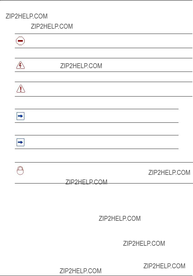
These symbols are used to highlight critical information:
Caution: Alerts you to conditions where you can damage the equipment.
Danger: Alerts you to conditions where you can get an electrical shock.
Warning: Alerts you to conditions where you can cause the system to fail or work improperly.
Note: A Note alerts you to important information.
Tip: Alerts you to additional information that can help you perform a task.
Security note: Indicates a point of system security where a default should be changed,
!or where the administrator needs to make a decision about the level of security required for the system.
Related publications
Related publications are listed below. To locate specific information, you can refer to the master index for the documentation suite for your system.
IP Phone 1120E User Guide
IP Phone 1140E User Guide

17
Chapter 2
Introduction
This document describes the Expansion Module for IP Phone 1100 Series (expansion module) and how to use it with the compatible IP Phone 1100 series telephones.
The following topics are covered in this chapter:
??????Expansion module overview??? on page 17
??????Setup and assembly??? on page 19
??????Controls and settings??? on page 19
??????Shift/Outbox key??? on page 19
??????Services key??? on page 19
??????Display Diagnostics menu??? on page 20
Expansion module overview
The expansion module is supported on the following IP Phones:
???IP Phone 1120E
???IP Phone 1140E
The expansion module is a hardware accessory that connects to an IP Phone to provide additional line and feature keys. The module is a graphical expansion module with 18
The supported IP Phone 1100 series phones can support a maximum of three expansion modules at one time. This allows the IP Phone 1120E and IP Phone 1140E to have a maximum of 54 additional line or feature keys with three expansion modules.
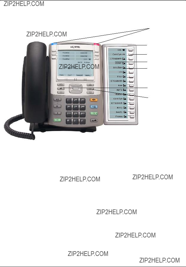
Figure 1 on page 18 shows the IP Phone 1140E with one expansion module attached.
Wall mounting
You can mount the expansion module with an IP Phone using the wall mount template and mounting bracket provided with your expansion module.
Expansion Module 1100 Series User Guide
18 Chapter 2 Introduction
Figure 1 IP Phone 1140E with expansion module
 Diagnostics LEDs
Expansion module
Line/feature keys
LCD
Line/feature key labels
Services key
 Shift/Outbox key
Display
The expansion module is equipped with a graphical,
To adjust the display and contrast on the expansion module, use the Contrast Adjustment option in the Telephone Options menu on the IP Phone. Any contrast changes you make on the IP phone also affect the expansion module display. The expansion module and IP Phone do not have separate contrast adjustments.
Whether the IP Phone is powered using local power or Power over Ethernet (PoE), the expansion module has the same backlight settings as the IP Phone. The backlight timer only turns off if the backlight timer is set.
For more information on how to adjust the display settings on the expansion module using the menus in your IP Phone, refer to the user guide for your IP Phone.

Chapter 2 Introduction 19
Setup and assembly
The expansion module mounts on the right side of the IP Phone. Snap the expansion module into the accessory expansion module (AEM) on the back of the IP Phone. For installation procedures see Chapter 3, ???Installing the expansion module,??? on page 21. You can also wall mount the expansion module with IP Phone.
Controls and settings
When you install an expansion module on an IP Phone, you control the settings of both the
IP Phone and the expansion module through the IP Phone. Use the Telephone Options menu on the attached IP Phone to set the contrast and line/feature key labels of the expansion module.
For more information on how to use your IP Phone to set the labels of your expansion module, see your IP Phone user guide.
Shift/Outbox key
The IP Phone 1140E can have up to 36 additional line/feature keys using the Shift/Outbox key functionality on your IP Phone. This feature, if it is supported by your Business Communication Manager (BCM), works if you have one expansion module already connected to your IP Phone. This gives your IP Phone a maximum of 54 additional line/feature keys.
If you install more than one expansion module on your IP Phone, the Shift/Outbox key functionality does not affect the expansion module because the maximum number of line/feature keys is already available.
The Shift/Outbox key on the IP Phone 1120E is a fixed key that is not currently supported.
Services key
Use the Services key on your IP Phone to access user settings and certain features on the IP Phone. When one or more expansion modules are attached to your IP Phone, the actions of the Display Diagnostics menu for your IP Phone line/feature key display area are duplicated for the expansion module.
Press the Services key of your IP Phone to access the following menu items:
???Display Diagnostics
???Set Info
Expansion Module 1100 Series User Guide

20 Chapter 2 Introduction
Display Diagnostics menu
Use the Up/Down navigation keys on your IP Phone to scroll the diagnostics menu and to access the following diagnostic operations for your IP Phone and expansion module.
???Full Contrast
???LED Test
???Character Test
Instructions are displayed in the LCDs of the IP Phone and the expansion module. The line/feature key display areas are blank.
Full Contrast
The IP Phone and the expansion module display areas are set to maximum (dark) contrast, including the line/feature key areas. All LEDs are off.
LED Test
The IP Phone and the expansion module LEDs are set to on. The display areas clear, including the line/feature key display areas.
Character Test
The IP Phone and the expansion module LEDs are set to off. The available character set is displayed across all writable areas of the display, including the line/feature key display areas. The telephone
Table 4 on page 20 shows the diagnostic operation on the IP Phone and the expansion module.
Table 4 Display diagnostic operation on the IP Phone and the expansion module
21
Chapter 3
Installing the expansion module
Complete the procedures in this chapter to install the expansion module for IP Phone 1100 Series phones. You must have an IP Phone 1120E and IP Phone 1140E in order to use an Expansion Module 1100 Series.
Installing an expansion module
Caution: Damage to equipment
To avoid damaging the equipment, remove the power (PeE cable or local power) from the IP Phone before you connect the expansion module.
You need a Phillips head screwdriver to complete this procedure.
1Press the tilt lever to adjust the stand angle on the IP Phone. You can adjust the stand angle to maximum, instead of removing the stand.
Adjustable stand
2At the back of the IP Phone, remove the rubber plug from the AEM port.
3Place the connecting arm of the expansion module behind the IP Phone.
4Align the expansion module connection plug with the AEM port on the back of the IP Phone.
5Insert the screws into the holes a the top and bottom of the connecting arm of the expansion module.
6Tighten the screws until they are snug.
Expansion Module 1100 Series User Guide
22 Chapter 3 Installing the expansion module
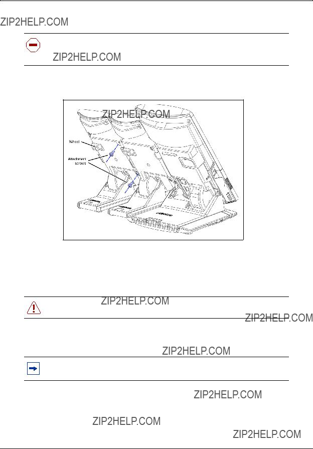
Installing a second or third expansion module
Caution: Damage to equipment
To avoid damaging the equipment, remove the power (PeE cable or local power) from the IP Phone before you connect the expansion module.
You need a Phillips head screwdriver to complete this procedure.
1 Attach the second expansion module to the right side of the first expansion module.
2Adjust the tilt of the IP Phone to a comfortable viewing angle.
3Adjust each of the expansion module foot stands so they are flush with the desk surface.
4Turn the wheel on the back
Warning: Do not over tighten the wheel on the expansion module.
5Connect power to the IP Phone. The expansion module powers up.
Note: The expansion module uses the electrical connection of the IP Phone for power. The expansion module does not have its own power source.
6 If required, repeat steps 1 to 5 to attach a third expansion module to the right side of the second expansion module.

Chapter 3 Installing the expansion module 23
Mounting the expansion module and phone on a wall
You can
Complete this procedure if you plan to mount the base station on a wall or ceiling. Skip this procedure if you plan to place the base station on a flat surface.
1Place the mounting template against the wall where you want to install the IP Phone and expansion module.
The template provides guidelines for mounting one IP Phone with up to two or more expansion modules.
2Use the mounting template to position the IP Phone and expansion module.
3Mark the screw positions.
4Use the screws to attach the mounting brackets to a wall.
5Align the notches on the back of the IP Phone and expansion module with the mounting bracket on the wall.
6Push the IP Phone and expansion module against the brackets until they are securely connected.
Adjusting the tilt base
The expansion module stand provides a continuous tilt adjustment so the tilt angle matches the IP Phone stand angle while accommodating variations in the desk surface. Use the clamp mechanism to unlock and lock the foot stand angle.
Caution: Risk of damaging equipment
Do not
1Turn the wheel on the back
2Adjust the angle of the IP Phone using the tilt lever.
3When the IP Phone is set to a preferred angle, turn the wheel on the back of the expansion module to tighten the foot stand hinge and lock the stand at the same angle as the attached IP Phone.
Expansion Module 1100 Series User Guide

24 Chapter 3 Installing the expansion module

25
Chapter 4
Expansion module startup initialization
Once you have installed and powered up the expansion module on the IP Phone, the expansion module initializes.
Table 5 on page 25 describes the initialization process for the expansion module.
Table 5 Initializing the expansion module
Expansion Module 1100 Series User Guide

26 Chapter 4 Expansion module startup initialization

27
Chapter 5
Using the handset
This section describes how to use the expansion module to
???make calls
???put a call on hold
???program indicator keys
???use features
There are many ways to place or answer a call, depending on how you program the indicator keys and the type of call you want to make.
Making a call using a line key
1Pick up the handset.
2Press a key on the expansion module that is programmed as a Line key. You hear a dial tone.
3Use the key pad to dial the external number or the internal extension.
Making a call using the speakerphone key
1Press the Speakerphone key. You hear a dial tone.
2Press a key on the expansion module that is programmed as a Line key to dial the external number or the internal extension.
Putting a call on hold
1While a call is active, press the  key on your IP Phone.
2To release the call and make it active again, press the flashing indicator key.
Expansion Module 1100 Series User Guide

28 Chapter 5 Using the handset
Programming indicator keys
You can program a programmable line or feature indicator key with a new number or feature.
Programming external autodial
1Press the Feature key.
2Enter *1 using the telephone dial pad.
3Press an indicator key.
4Dial the external number.
5Select OK to store the number.
Programming internal autodial
1Press the Feature key.
2Enter *2 using the telephone dial pad.
3Press an indicator key.
4Dial the extension.
5Select OK to store the number.
Programming a feature
1Press the Feature key.
2Enter *3 using the dial pad.
3Press an indicator key.
4Select Feature.
5Enter the feature code.
6Select OK to store the feature code.
Erasing a programmed indicator keys
1Press the Feature key.
2Enter *1 using the dial pad.
3Press an indicator key.
4Select OK to erase the indicator key.