Patent Pending

Model No. NEL7095.1

Serial Number

Decal

QUESTIONS?

As a manufacturer, we are com- mitted to providing complete customer satisfaction. If you have questions, or if parts are damaged or missing, PLEASE

CONTACT OUR CUSTOMER

SERVICE DEPARTMENT

DIRECTLY.

CALL TOLL-FREE:

1-888-825-2588

Mon.???Fri., 6 a.m.???6 p.m. MST

ON THE WEB: www.nordictrackservice.com

CAUTION

Read all precautions and instruc- tions in this manual before using this equipment. Keep this manual for future reference.

USER???S MANUAL

Visit our website at

www.nordictrack.com

new products, prizes, fitness tips, and much more!

TABLE OF CONTENTS

IMPORTANT PRECAUTIONS . . . . . . . . . . . . . . . . . . . . . . . . . . . . . . . . . . . . . . . . . . . . . . . . . . . . . . . . . . . . . . . .3 BEFORE YOU BEGIN . . . . . . . . . . . . . . . . . . . . . . . . . . . . . . . . . . . . . . . . . . . . . . . . . . . . . . . . . . . . . . . . . . . . . .4 ASSEMBLY . . . . . . . . . . . . . . . . . . . . . . . . . . . . . . . . . . . . . . . . . . . . . . . . . . . . . . . . . . . . . . . . . . . . . . . . . . . . . . .5 HOW TO USE THE ELLIPTICAL EXERCISER . . . . . . . . . . . . . . . . . . . . . . . . . . . . . . . . . . . . . . . . . . . . . . . . . . .9 MAINTENANCE AND TROUBLESHOOTING . . . . . . . . . . . . . . . . . . . . . . . . . . . . . . . . . . . . . . . . . . . . . . . . . . .21 CONDITIONING GUIDELINES . . . . . . . . . . . . . . . . . . . . . . . . . . . . . . . . . . . . . . . . . . . . . . . . . . . . . . . . . . . . . . .23 PART LIST . . . . . . . . . . . . . . . . . . . . . . . . . . . . . . . . . . . . . . . . . . . . . . . . . . . . . . . . . . . . . . . . . . . . . . . . . . . . . .24 EXPLODED DRAWING . . . . . . . . . . . . . . . . . . . . . . . . . . . . . . . . . . . . . . . . . . . . . . . . . . . . . . . . . . . . . . . . . . . .26 HOW TO ORDER REPLACEMENT PARTS . . . . . . . . . . . . . . . . . . . . . . . . . . . . . . . . . . . . . . . . . . . . .Back Cover LIMITED WARRANTY . . . . . . . . . . . . . . . . . . . . . . . . . . . . . . . . . . . . . . . . . . . . . . . . . . . . . . . . . . . . . .Back Cover

NordicTrack is a registered trademark of ICON IP, Inc.

2

IMPORTANT PRECAUTIONS

WARNING: To reduce the risk of serious injury, read the following important precau- tions before using the elliptical exerciser.

1.Read all instructions in this manual and all warnings on the elliptical exerciser before using the elliptical exerciser.

2.It is the responsibility of the owner to ensure that all users of the elliptical exerciser are adequately informed of all precautions.

3.The elliptical exerciser is intended for in-home use only. Do not use the elliptical exerciser in a commercial, rental, or institu- tional setting.

4.Keep the elliptical exerciser indoors, away from moisture and dust. Place the elliptical exerciser on a level surface, with a mat beneath it to protect the floor or carpet. Make sure that there is enough clearance around the elliptical exerciser to mount, dis- mount, and use the elliptical exerciser.

5.Inspect and properly tighten all parts regu- larly. Replace any worn parts immediately.

6.Keep children under age 12 and pets away from the elliptical exerciser at all times.

7.The elliptical exerciser should not be used by persons weighing more than 250 pounds.

8.Wear appropriate exercise clothes when using the elliptical exerciser. Always wear athletic shoes for foot protection.

9.Always hold the handlebars when mounting, dismounting, or using the elliptical exerciser.

10.Keep your back straight when using the ellip- tical exerciser; do not arch your back.

11.If you feel pain or dizziness while exercis- ing, stop immediately and cool down.

12.The pulse sensor is not a medical device. Various factors, including the user's move- ment, may affect the accuracy of heart rate readings. The pulse sensor is intended only as an exercise aid in determining heart rate trends in general.

13.When you stop exercising, allow the pedals to slowly come to a complete stop. The ellip- tical exerciser does not have a free wheel; the pedals will continue to move until the flywheel stops.

14.Always unplug the power cord immediately after use and before cleaning the elliptical exerciser.

15.The decal shown below has been placed on the elliptical exerciser. If the decal is missing or illegible, call the toll-free telephone num- ber on the front cover of this manual and order a free replacement decal. Apply the decal in the location shown.

WARNING: Before beginning this or any exercise program, consult your physician. This is especially important for persons over the age of 35 or persons with pre-existing health prob- lems. Read all instructions before using. ICON assumes no responsibility for personal injury or property damage sustained by or through the use of this product.

3

BEFORE YOU BEGIN

Congratulations for selecting the new NordicTrack?? CX 998 elliptical exerciser. The CX 998 is an incredi- bly smooth exerciser that moves your feet in a natural elliptical path, minimizing the impact on your knees and ankles. And the unique CX 998 features adjustable resistance and incline to help you get the most from your exercise. Welcome to a whole new world of natural, elliptical-motion exercise from NordicTrack.

For your benefit, read this manual carefully before you use the elliptical exerciser. If you have ques-

tions after reading this manual, please see the front cover of this manual. To help us assist you, please note the product model number and serial number before calling. The model number is NEL7095.1. The serial number can be found on a decal attached to the elliptical exerciser (see the front cover of this manual for the location of the decal).

Before reading further, please familiarize yourself with the parts that are labeled in the drawing below.

ASSEMBLY

Assembly requires two persons. Place all parts of the elliptical exerciser in a cleared area and remove the packing materials. Do not dispose of the packing materials until assembly is completed. In addition to the included allen wrenches, assembly requires a phillips screwdriver , two adjustable wrenches , a rubber mallet , and pliers .

As you assemble the elliptical exerciser, use the drawings below to identify the small parts used in assembly. The number in parenthesis below each drawing is the key number of the part, from the PART LIST on pages 24 and 25. The second number is the quantity used in assembly. Note: Some small parts may have been pre- assembled. If a part is not in the parts bag, check to see if it is pre-assembled.

5

2.Identify the Pivot Axle (14), which is the longer of the two axles. Slide a Ramp Cover (48) onto an M6 x 16mm Patch Screw (76) as shown. Tighten the Patch Screw into one end of the Pivot Axle. Apply a small amount of the included grease to the Pivot Axle.

Have a second person hold the two Ramp Spacers (99) against the sides of the Frame (1) so they cover the indicated tubes on the Frame. Align the round tubes on the Ramp (3) with the Ramp Spacers. Make sure that the Ramp is turned as shown in drawing 3 below. Insert the Pivot Axle (14) into the Ramp, the Ramp Spacers, and the Frame. If necessary, use a rubber mallet to fully insert the Pivot Axle.

Slide the other Ramp Cover (48) onto an M6 x 16mm Patch Screw (76) as shown. Tighten the Patch Screw into the open end of the Pivot Axle (14).

3.Slide an M6 Washer (64) onto an M6 x 16mm Patch Screw (76). Tighten the Patch Screw into one end of the Incline Axle (13). Apply a small amount of grease to the Incline Axle.

Raise the Ramp (3). Insert the Incline Axle (13) into the welded tube under one side of the Ramp, through the motor screw, and then into the welded tube under the other side of the Ramp. As you insert the Incline

Axle through the motor screw, make sure that the motor screw does not turn.

Slide an M6 Washer (64) onto an M6 x 16mm Patch Screw (76). Tighten the Patch Screw into the open end of the Incline Axle (13).

4.Have another person hold the Upright (2) in the posi- tion shown.

Connect the Upper Wire Harness (115) to the Lower Wire Harness (42). Insert the connectors on the Wire Harnesses up into the Upright (2). Carefully pull the upper end of the Upper Wire Harness to remove the slack from the Wire Harnesses. See the inset drawing. Attach the Lower Wire Harness to the Upright with the Nylon Zip Tie (125). Pull the Nylon Zip Tie tight and cut off the excess.

Insert the Upright (2) into the Frame (1). Be careful to avoid pinching the Wire Harnesses (115, 42). Attach the Upright with two M10 x 108mm Button Screws (70), two M10 Split Washers (73), and two 7.6mm Spacers (109). Make sure that the curved sides of the Spacers are facing the Upright. Be careful to avoid damaging the Wire Harnesses with the Button Screws. Do not tighten the the Button Screws yet.

6

5.Slide a Weld Spacer (119) onto the axle on the left side of the Upright (2), with the open side of the Weld Spacer facing the Upright. Apply a generous amount of grease to the axle.

Hold one of the Upper Body Arms (118) with one hand, hold the Upper Body Leg (31) with your other hand, and slide the Upper Body Arm onto the axle on the left side of the Upright (2). Next, extend the Upper Body Leg and apply half of the included high-temperature lubricant. Then, rest the end of the Upper Body Leg on the Ramp (3).

Have another person hold the Left Handlebar (24) near the Upright (2) as shown. Connect the left Pulse Sensor Wire (20) to the Pulse Extension Wire (114).

Slide the upper end of the Left Handlebar (24) into the tube on the front of the Upright (2), while sliding the lower end of the Left Handlebar onto the axle on the left side of the Upright. Attach the upper end of the Left Handlebar with two M8 x 41mm Button Bolts (85) and two M8 Jam Nuts (86); be careful not to damage the

Wires (20, 114) as you insert the Button Bolts. Make sure that the Jam Nuts are resting in the hexagonal holes in the Left Handlebar. Attach the lower end of the Left Handlebar with an M8 x 38mm Button Bolt (105) and an M8 Jam Nut (86).

Attach the other Upper Body Arm (118) and the Right Handlebar (23) in the same way.

6.Look inside one of the Handlebar Cover Sets (26) and locate the square tabs connecting the two halves. Gently lift the tabs and disconnect the halves.

Hold the two halves of the Handlebar Cover Set (26) around the tube on the left side of the Upright (2). Align the halves and press them together until they lock.

Attach the other Handlebar Cover Set (26) to the right side of the Upright (2) in the same way.

Hold the halves of the Upper Handlebar Cover (25) around the tube on the front of the Upright (2); be careful not to damage the Wires (not shown).

Attach the Upper Handlebar Cover with an M4 x 12mm Round Head Screw (96).

7

7.Apply a liberal amount of grease to the barrel of each M8 x 79mm Bolt Set (65).

Identify the Left Pedal (10), which has a notch near the right side. Place the Left Pedal on the Left Pedal Leg (4). Have a second person hold the bracket on the left Upper Body Leg (31) inside of the bracket on the Left Pedal Leg, and hold a Pedal Wheel (28) inside of the bracket on the left Upper Body Leg.

Align the indicated holes, and attach the Left Pedal (10), the left Upper Body Leg (31), and the Wheel (28) to the Left Pedal Leg (4) with an M8 x 79mm Bolt Set (65). Attach the other end of the Left Pedal to the Left Pedal Leg with two M8 x 56mm Button Screws (83) and two M8 Split Washers (30).

Repeat this step on the right side of the elliptical exerciser.

See step 4. Tighten the two M10 x 108mm Button Screws (70).

8.Have another person hold the Console (17) near the Upright (2).

Connect the Upper Wire Harness (115) to the wire har- ness on the Console (17). Connect the Pulse Extension Wire (114) to the pulse wire on the Console.

Carefully insert all excess wiring down into the Upright

(2). Attach the Console to the Upright with four M4 x 16mm Round Head Screws (69). (Note: The Round Head Screws may be found in the console box.) Be careful to avoid pinching the wires.

9.Plug the Power Cord (116) into the Power Socket (117) at the rear of the elliptical exerciser.

10.Make sure that all parts of the elliptical exerciser are properly tightened. Cover the floor beneath the elliptical exerciser to protect the floor from damage. Note: Some extra hardware may be left over.

8

Grounded Outlet Box Grounding Plug
Grounding Pin Grounded Outlet

HOW TO USE THE ELLIPTICAL EXERCISER

HOW TO PLUG IN THE POWER CORD

This product must be grounded.

If it should malfunction or break down, grounding provides a path of least resistance for electric

current to reduce the risk of electric shock. This prod- uct is equipped with a cord having an equipment- grounding conductor and a grounding plug. Plug the power cord into an appropriate outlet that is prop- erly installed and grounded in accordance with all local codes and ordinances. This product is for use on a nominal 120-volt circuit. Important: The elliptical exerciser is not compatible with GFCI- equipped outlets.

DANGER: Improper connection of the equipment-grounding conductor can result in an increased risk of electric shock. Check with a qualified electrician or serviceman if you are in doubt as to whether the product is properly grounded. Do not modify the plug provided with the product???if it will not fit the outlet, have a proper outlet installed by a qual- ified electrician.

outlet is not

available. The temporary adapter should be used only until a properly grounded outlet can be installed by a qualified electrician.

The green-colored rigid ear, lug, or the like extending from the adapter must be connected to a permanent ground such as a properly grounded outlet box cover. Whenever the adapter is used, it must be held in place by a metal screw. Some 2-pole receptacle out- let box covers are not grounded. Contact a quali- fied electrician to determine if the outlet box cover is grounded before using an adapter.

Note: When the power cord is plugged in, the ellip- tical exerciser???s incline system may automatically calibrate itself. During the calibration process, three dashes (??? ??? ???) will appear in the console dis- play while the ramp moves to the highest position and then returns to the lowest position.

EXERCISING ON THE ELLIPTICAL EXERCISER

To mount the elliptical exerciser, hold the handlebars and step onto the pedal that is in the lowest position. Next, step onto the other pedal. Push the pedals until they begin to move with a continuous motion.

To dismount the elliptical exerciser, wait until the ped- als come to a complete stop. The elliptical exerciser does not have a free wheel; the pedals will contin- ue to move until the flywheel stops. When the ped- als are stationary, step off the highest pedal first.

Then, step off the lowest pedal.

9

CONSOLE DIAGRAM

Note: If there is a sheet of clear plastic on the face of the console, remove it before using the console.

FEATURES OF THE CONSOLE

The advanced console offers a selection of features designed to make your workouts more enjoyable and effective. When the manual mode of the console is selected, the resistance of the pedals and the angle of the ramp can be changed with the touch of a button. As you exercise, the console will provide continuous exercise feedback. You can even measure your heart rate using the handgrip pulse sensor.

The console also offers eight preset programs. Each program automatically changes the resistance of the pedals and prompts you to increase or decrease your pace as it guides you through an effective workout.

In addition, the console features two heart rate pro- grams that automatically change the resistance of the pedals and prompt you to vary your pace to keep your heart rate near a target heart rate while you exercise.

The console also features iFIT.com interactive technol- ogy. Having iFIT.com technology is like having a per- sonal trainer in your home. Using the included stereo

audio cable, you can connect the elliptical exerciser to your portable stereo, home stereo, computer, or VCR and play special iFIT.com CD and video programs (iFIT.com CDs and videocassettes are available sepa- rately). iFIT.com programs automatically control the resistance of the pedals and prompt you to vary your pace as a personal trainer coaches you through every step of your workout. High-energy music provides added motivation. To purchase iFIT.com CDs and videocassettes, call the toll-free telephone number on the front cover of this manual.

With the elliptical exerciser connected to your comput- er, you can also go to our Web site at www.iFIT.com and access programs directly from the internet.

Explore www.iFIT.com for more information.

To use the manual mode of the console, follow the steps beginning on page 11. To use a preset program, see page 13. To use a heart rate program, see page 14. To use an iFIT.com CD or video pro- gram, see page 19. To use an iFIT.com program directly from our Web site, see page 20.

10

HOW TO USE THE MANUAL MODE

Press any button on the console or begin 1 pedaling to turn on the console.

Make sure that the power cord is properly plugged in (see page 9). To activate the con- sole, press any button or begin pedaling. After a few seconds, the displays will light. A tone will then sound and the console will be ready for use.

2 Select the manual mode.

If you have selected

a program or the iFIT.com mode, rese- lect the manual mode by pressing the iFIT button once or twice

until a track appears

in the matrix but the letters ???iFIT??? do not appear.

Change the resistance of the pedals and the 3 angle of the ramp as desired.

As you pedal,

change the resis- tance of the pedals by pressing the 1 Step Resistance but- tons. Note: After the

buttons are pressed,

it will take a moment for the pedals to reach the selected resistance level.

To vary the feel of your exercise, increase or decrease the angle of the ramp by pressing the

1 Step Ramp but- tons. There are five

ramp angles. Note: After the buttons are pressed, it will take a moment for the ramp to reach the selected angle.

Monitor your progress with the matrix, the 4 Training Zones bar, and the displays.

The matrix???When the manual mode or the iFIT.com mode is selected, the matrix will show a track rep- resenting 1/4 mile. As

you exercise, the indicators around the track will light in succession until the entire track is lit. The track will then darken and the indicators will again begin to light in succession.

The Training Zones bar???The Training Zones bar will show the approximate inten- sity level of your exer- cise.

The upper display???

The upper display will show the approximate number of grams of carbs you have burned, the approxi- mate number of calo-

ries you have burned, the distance you have ped- aled, and the elapsed time. The display will change from one number to the next every few seconds. Note: When a program is selected, the display will show the time remaining in the pro- gram instead of the elapsed time.

To see the total distance pedaled since the ellipti- cal exerciser was purchased, press the Odometer button twice; the words ???Total Dist.??? and the total number of miles will appear in the display. To again see the distance that you have pedaled during your workout, press the Odometer button again.

The lower display???

The lower display will show your pedaling pace, in revolutions per minute (RPM), your pedaling speed,

and the resistance

level of the pedals. The display will change from one number to the next every few seconds. The display will also show your heart rate when you use the handgrip pulse sensor.

11

Note: The console can show speed and distance in either miles or kilo- meters. The letters

MPH or Km/H will appear in the lower

display to show which unit of measurement is selected. To change the unit of measurement, first hold down the Start button for a few seconds. An E (for English) or an M (for metric) will appear in the lower display. Press the 1 Step Resistance 10 but- ton to change the unit of measurement.

While you are select- ing a unit of mea-

surement, you can

also select a back- light mode. The ???On??? mode keeps the backlight on while

the console is on. The ???Off??? mode turns the back- light off. The ???Auto??? mode keeps the backlight on only while you are exercising. Press the 1 Step Resistance 1 button to change the backlight mode if desired. Then, press the Start button.

5 Measure your heart rate if desired.

When your pulse is detected, your heart rate will be shown in the lower display. For the most accurate heart rate reading, hold the contacts for at least 15 seconds.

Note: If you continue to hold the handgrip pulse sensor, the lower display will show your heart rate for up to 30 seconds. The display will then show your heart rate along with the other modes.

If your heart rate is not shown, make sure that your hands are positioned as described. Be care- ful not to move your hands excessively or to squeeze the metal contacts too tightly. For opti- mal performance, clean the metal contacts using a soft cloth; never use alcohol, abrasives, or chemicals.

6 Turn on the fan if desired.

To turn on the fan at low speed, press the Auto Breeze Fan but-

ton; the number 1 will appear next to the word ???Fan??? in the dis- play. To turn on the

fan at medium speed, press the button a second time; the number 2 will appear. To turn on the fan at high speed, press the button a third time; the number 3 will appear. To select the auto mode, press the button again; the words ???Auto Fan??? will appear. When the auto mode is selected, the speed of the fan will automatically increase or decrease as you increase or decrease your ped- aling speed.

To turn off the fan, press the Auto Breeze Fan button again. Note: If the pedals are not turned for a few minutes, the fan will automatically turn off.

Slide the thumb tab on the right side of the fan to pivot the fan to the desired angle.

When you are finished exercising, the console 7 will automatically turn off.

If the pedals are not moved for several seconds, a tone will sound, the console will pause, and the time will begin to flash in the upper display.

If the pedals are not moved for about five min- utes, the console will turn off and the displays will be reset.

12

Current Segment

HOW TO USE A PRESET PROGRAM

Press any button on the console or begin 1 pedaling to turn on the console.

See step 1 on page 11.

2 Select one of the eight preset programs.

To select one of the eight preset pro-

grams, press the Resistance/Pace Programs button repeatedly until ???P 1,??? ???P 2,??? ???P 3,???

???P 4,??? ???P 5,??? ???P 6,??? ???P 7,??? or ???P 8??? appears in the upper display.

When a preset program is selected, a profile of the resistance settings of the program will scroll across the matrix and the maximum resistance setting of the program will flash in the lower dis- play. A few seconds after a program is selected, the upper display will show how long the program will last.

Press the Start button or begin pedaling to 3 start the program.

Each program is divided into several one-minute segments. One resistance setting and one pace setting are programmed for each segment. Note: The same resistance setting and/or pace setting may be programmed for two or more consecutive segments.

The resistance setting for the first segment will be

shown in the flashing Current Segment column of the matrix. (The

pace settings are not shown in the matrix.) The resistance settings for the next several segments will be shown in the columns to the right.

As you exercise, the Target Pace guide will help you to keep your pedaling pace near the pace setting for the current segment. When one of the ???Too Slow??? indicators lights, increase your pace.

When the one of the ???Too Fast??? indicators lights, decrease your pace. When the ???On Pace??? indica- tor lights, maintain your current pace.

Important: The pace settings are intended only to provide motivation. Your actual pace may be slower than the pace settings. Make sure to exercise at a pace that is comfortable for you.

When only three seconds remain in the first seg- ment of the program, both the Current Segment column and the column to the right will flash, a series of tones will sound, and all resistance set- tings will move one column to the left. The resis- tance setting for the second segment will then be shown in the flashing Current Segment column, and the resistance of the pedals will change to the resistance setting for the second segment. Note: If all of the indicators in the Current Segment col- umn are lit after the resistance settings have moved to the left, the resistance settings may move downward so only the highest indicators appear in the matrix.

The program will continue until the resistance setting for the last segment is shown in the Current Segment column and the last segment ends.

Note: During the program, you can override the resistance setting for the current segment, if desired, by pressing the 1 Step Resistance but- tons. However, when the next segment begins, the resistance will change if a different resistance setting is programmed for the next segment. In addition, you can change the angle of the ramp, if desired, by pressing the 1 Step Ramp buttons.

If you stop pedaling for several seconds, a tone will sound and the program will pause. To restart the program, simply resume pedaling.

13

4 Monitor your progress with the displays.

See step 4 on page 11.

5 Measure your heart rate if desired.

See step 5 on page 12.

6 Turn on the fan if desired.

See step 6 on page 12.

When you are finished exercising, the con- 7 sole will automatically turn off.

See step 7 on page 12.

HOW TO USE A HEART RATE PROGRAM

Press any button on the console or begin 1 pedaling to turn on the console.

See step 1 on page 11.

2 Select one of the two heart rate programs.

To select a heart rate

program, press the Heart Rate Control Programs button once

or twice until ???P 9??? or ???P10??? appears in the upper display. A few

seconds after a program is selected, the upper display will show how long the program will last.

If the first heart rate program (P 9) is selected, a profile of the target heart rate settings of the pro- gram will scroll across the matrix.

If the second heart rate program (P10) is selected, a pulse symbol will appear in the matrix.

3 Enter a target heart rate setting.

If the first heart rate program is selected,

the maximum target heart rate setting of

the program will flash in the lower display. If

desired, press the

increase and decrease buttons to change the maximum target heart rate setting (see EXER- CISE INTENSITY on page 23). Note: If the maxi- mum target heart rate setting is changed, the intensity level of the entire program will change.

If the second heart rate program is selected, the target heart rate setting for the program will flash in the lower display. If desired, press the increase and decrease buttons to change the tar- get heart rate setting (see EXERCISE INTENSI- TY on page 23). Note: The same target heart rate setting will be programmed for all segments.

14

Current Segment

4 Hold the handgrip pulse sensor.

To use a heart rate program, you must use the handgrip pulse sensor. It is not necessary to hold the handgrip pulse sensor continuously during the program; however, you should hold the hand- grip pulse sensor frequently for the program to operate properly. Each time you hold the hand- grip pulse sensor, keep your hands on the metal contacts for at least 30 seconds.

5 Press the Start button to start the program.

First heart rate program???This program is divid- ed into 20 one-minute segments. One target heart rate setting is programmed for each seg- ment. Note: The same target heart rate setting may be programmed for two or more consecutive segments.

The target heart rate setting for the

first segment will be shown in the flashing Current Segment column of the matrix. The

target heart rate

settings for the next several segments will be shown in the columns to the right.

When only three seconds remain in the first seg- ment of the program, both the Current Segment column and the column to the right will flash, a series of tones will sound, and all target heart rate settings will move one column to the left.

The target heart rate setting for the second seg- ment will then be shown in the flashing Current Segment column.

Second heart rate program???This program is divided into 40 one-minute segments. The same target heart rate is programmed for all segments. Note: For a shorter workout, stop exercising or select a different program before the program ends.

Both heart rate programs???As you pedal, the console will regularly compare your heart rate to the target heart rate setting. If your heart rate is too far below or above the target heart rate set- ting, the resistance of the pedals will automatical- ly increase or decrease to bring your heart rate closer to the target heart rate setting.

The Target Pace guide will prompt you to increase or decrease your pedaling pace during the program. When one of the ???Too Slow??? indica- tors lights, increase your pace. When the one of the ???Too Fast??? indicators lights, decrease your pace. When the ???On Pace??? indicator lights, main- tain your current pace.

Important: The target heart rate settings are intended only to provide motivation. Your actual heart rate may be slower than the tar- get heart rate settings. Make sure to exercise at a pace that is comfortable for you.

Note: During the program, you can manually over- ride the resistance setting for the current seg- ment, if desired, with the 1 Step Resistance but- tons. However, when the console compares your heart rate to the target heart rate setting, the resistance of the pedals may automatically increase or decrease to bring your heart rate closer to the target heart rate setting. In addition, you can change the angle of the ramp, if desired, by pressing the 1 Step Ramp buttons.

If you stop pedaling for several seconds, a tone will sound and the program will pause. To restart the program, simply resume pedaling.

6 Monitor your progress with the displays.

See step 4 on page 11.

7 Turn on the fan if desired.

See step 6 on page 12.

When you are finished exercising, the con- 8 sole will automatically turn off.

See step 7 on page 12.

15

HOW TO CONNECT YOUR CD PLAYER, VCR,

OR COMPUTER

To use iFIT.com CDs, the elliptical exerciser must be connected to your portable CD player, portable stereo, home stereo, or computer with CD player. See pages 16 and 17 for connecting instructions. To use iFIT.com videocassettes, the elliptical exerciser must be con- nected to your VCR. See page 18 for connecting instructions. To use iFIT.com programs directly from our Web site, the elliptical exerciser must be connect- ed to your home computer. See page 17 for connect- ing instructions.

HOW TO CONNECT YOUR PORTABLE CD PLAYER

Note: If your CD player has separate LINE OUT and PHONES jacks, see instruction A below. If your CD player has only one jack, see instruction B.

A.Plug one end of the audio cable into the jack beneath the console. Plug the other end of the cable into the LINE OUT jack on your CD player. Plug your headphones into the PHONES jack.

B.Plug one end of the audio cable into the jack beneath the console. Plug the other end of the cable into a 1/8??? Y-adapter (available at electronics stores). Plug the Y-adapter into the PHONES jack on your CD player. Plug your headphones into the other side of the Y-adapter.

HOW TO CONNECT YOUR PORTABLE STEREO

Note: If your stereo has an RCA-type AUDIO OUT jack, see instruction A below. If your stereo has a 1/8??? LINE OUT jack, see instruction B. If your stereo has only a PHONES jack, see instruction C.

A.Plug one end of the audio cable into the jack beneath the console. Plug the other end of the cable into the adapter. Plug the adapter into an AUDIO OUT jack on your stereo.

B.Plug one end of the audio cable into the jack beneath the console. Plug the other end of the cable into the LINE OUT jack on your stereo. Do not use the adapter.

C.Plug one end of the audio cable into the jack beneath the console. Plug the other end of the cable into a 1/8??? Y-adapter (available at electronics stores). Plug the Y-adapter into the PHONES jack on your stereo. Plug your headphones into the other side of the Y-adapter.

16

HOW TO CONNECT YOUR HOME STEREO

Note: If your stereo has an unused LINE OUT jack, see instruction A below. If the LINE OUT jack is being used, see instruction B.

HOW TO CONNECT YOUR COMPUTER

Note: If your computer has a 1/8??? LINE OUT jack, see instruction A. If your computer has only a PHONES jack, see instruction B.

A.Plug one end of the audio cable into the jack beneath the console. Plug the other end of the cable into the adapter. Plug the adapter into the LINE OUT jack on your stereo.

B.Plug one end of the audio cable into the jack beneath the console. Plug the other end of the cable into the adapter. Plug the adapter into an RCA Y-adapter (available at electronics stores). Next, remove the wire that is currently plugged into the LINE OUT jack on your stereo and plug the wire into the unused side of the Y-adapter. Plug the Y-adapter into the LINE OUT jack on your stereo.

A.Plug one end of the audio cable into the jack beneath the console. Plug the other end of the cable into the LINE OUT jack on your computer.

B.Plug one end of the audio cable into the jack beneath the console. Plug the other end of the cable into a 1/8??? Y-adapter (available at electronics stores). Plug the Y-adapter into the PHONES jack on your computer. Plug your headphones or speak- ers into the other side of the Y-adapter.

17

HOW TO CONNECT YOUR VCR

Note: If your VCR has an unused AUDIO OUT jack, see instruction A below. If the AUDIO OUT jack is being used, see instruction B. If you have a TV with a built-in VCR, see instruction B. If your VCR is connected to your home stereo, see HOW TO CONNECT YOUR HOME STEREO on page 17.

A.Plug one end of the audio cable into the jack beneath the console. Plug the other end of the cable into the adapter. Plug the adapter into the AUDIO OUT jack on your VCR.

A

ANT. IN

VIDEO AUDIO

IN

RF OUT

CH 3 4

OUT

AUDIO OUT

RIGHT

LEFT

Adapter

Audio Cable

B.Plug one end of the audio cable into the jack beneath the console. Plug the other end of the cable into the adapter. Plug the adapter into an RCA Y-adapter (available at electronics stores). Next, remove the wire that is currently plugged into the AUDIO OUT jack on your VCR and plug the wire into the unused side of the Y-adapter. Plug the Y-adapter into the AUDIO OUT jack on your VCR.

B

ANT. IN

VIDEO AUDIO

IN

RF OUT

CH 3 4

OUT

RCA Y-adapter

Wire removed from

AUDIO OUT jack

18

HOW TO USE AN IFIT.COM CD OR VIDEO

PROGRAM

To use an iFIT.com CD or video program, the elliptical exerciser must be connected to your CD player or VCR. See HOW TO CONNECT YOUR CD PLAYER, VCR, OR COMPUTER on pages 16 to 18. To pur- chase iFIT.com CDs or videocassettes, call the toll- free telephone number on the front cover of this manual.

Follow the steps below to use an iFIT.com CD or video program.

The program will function in almost the same way as a preset program (see step 3 on page 13). However, an electronic ???chirping??? sound will alert you when the resistance setting and/or pace set- ting is about to change.

Note: If the resistance of the pedals and/or the pace setting does not change when a ???chirp??? is heard:

???Make sure that the letters ???iFIT??? appear in the display.

???Adjust the volume of your CD player or VCR. If the volume is too high or too low, the con- sole may not detect the program signals.

Press any button on the console or begin 1 pedaling to turn on the console.

???Make sure that the audio cable is properly connected and that it is fully plugged in.

See step 1 on page 11.

Note: If you are using an iFIT.com CD, insert the CD into your CD player; if you are using an iFIT.com videocassette, insert the videocassette into your VCR.

A moment after the play button is pressed, your personal trainer will begin guiding you through your workout. Simply follow your personal trainer???s instructions.

See step 7 on page 12.

19

HOW TO USE PROGRAMS DIRECTLY FROM

OUR WEB SITE

Our Web site at www.iFIT.com allows you to play iFIT.com programs directly from the internet. To use programs from our Web site, the elliptical exerciser must be connected to your home computer. See HOW TO CONNECT YOUR COMPUTER on page 17. In addition, you must have an internet connection and an internet service provider. A list of specific system requirements is found on our Web site.

Follow the steps below to use a program from our Web site.

Press any button on the console or begin 1 pedaling to turn on the console.

See step 1 on page 11.

2 Select the iFIT.com mode.

See step 2 on page 19.

Go to your computer and start an internet 3 connection.

Start your Web browser, if necessary, and go 4 to our Web site at www.iFIT.com.

Follow the desired links on our Web site to 5 select a program.

Read and follow the on-line instructions for using a program.

Follow the on-line instructions to start the 6 program.

When you start the program, an on-screen count- down will begin.

Return to the elliptical exerciser and begin 7 pedaling.

When the on-screen countdown ends, the pro- gram will begin. The program will function in almost the same way as a preset program (see step 3 on page 13). However, an electronic ???chirp- ing??? sound will alert you when the resistance set- ting and/or pace setting is about to change.

8 Monitor your progress with the displays.

See step 4 on page 11.

9 Measure your heart rate if desired.

See step 5 on page 12.

10 Turn on the fan if desired.

See step 6 on page 12.

11 When you are finished exercising, the con- sole will automatically turn off.

See step 7 on page 12.

20

MAINTENANCE AND TROUBLESHOOTING

Inspect and properly tighten all parts of the elliptical exerciser regularly. Replace any worn parts immedi- ately.

Keep liquids off the console. Never use abrasives or solvents.

PULSE SENSOR TROUBLESHOOTING

If the handgrip pulse sensor does not function proper- ly, see step 5 on page 12.

HOW TO CALIBRATE THE INCLINE SYSTEM

If the elliptical exerciser???s ramp does not function prop- erly, press one of the 1 Step Ramp buttons; while the ramp is moving, unplug the power cord. When the power cord is plugged back in, the elliptical exercis- er???s incline system will automatically calibrate itself. During the calibration process, three dashes (??? ??? ???) will appear in the console display while the ramp moves to the highest position and then returns to the lowest position.

HOW TO MOVE THE ELLIPTICAL EXERCISER

Stand in front of the elliptical exerciser, hold the han- dlebars firmly, and place one foot against the ramp in the location shown below. Pull the handlebars until the elliptical exerciser can be moved on the front wheels, and carefully move the elliptical exerciser to the desired location. Then, place one foot against the ramp and lower the elliptical exerciser. Due to the size and weight of the elliptical exerciser, use extreme caution while moving and lowering it.

HOW TO LEVEL THE ELLIPTICAL EXERCISER

If the elliptical exerciser rocks during use, turn one or both of the leveling feet under the rear stabilizer until the rocking motion is elimi- nated.

21

HOW TO REMOVE THE SIDE SHIELDS AND THE

FLYWHEEL COVERS

The Left and Right Side Shields (15, 16) must be removed before the reed switch or the drive belt can be adjusted. To remove the Side Shields, remove the indicated Screws (69, 95, 108). Note which hole each Screw is removed from; the Screws will later need to be reattached in the same holes. Carefully separate and remove the Side Shields.

removed from; the Screws will later need to be reat- tached in the same holes. Carefully separate and remove the Flywheel Covers.

HOW TO ADJUST THE REED SWITCH

If the console does not display correct feedback, the reed switch should be adjusted. To adjust the reed switch, first see the instructions at the left and remove the side shields and the flywheel covers.

Next, see the drawing below. Locate the Reed Switch (55). Turn the Left Crank Arm (34) until the Magnet (37) is aligned with the Reed Switch. Loosen, but do not remove, the indicated Screw (98). Slide the Reed Switch slightly closer to or away from the Magnet, and then retighten the Screw. Turn the Left Crank Arm for a moment. Repeat until the console displays correct feedback. When the Reed Switch is correctly adjust- ed, reattach the side shields and the flywheel covers.

HOW TO ADJUST THE DRIVE BELT

If you can feel the pedals slip while you are pedaling, even when the resistance is adjusted to the highest setting, the drive belt may need to be adjusted. To adjust the drive belt, first see the instructions at the left and remove the side shields and the flywheel covers.

Next, see the drawing above. Loosen the indicated Bolt (75). Turn the indicated Screw (74) clockwise until the Drive Belt (113) is properly tightened, and then retighten the Bolt (75). Then, reattach the side shields and the flywheel covers.

22

CONDITIONING GUIDELINES

WARNING:

Before beginning this or any exercise pro- gram, consult your physician. This is espe- cially important for persons over the age of 35 or persons with pre-existing health problems.

The pulse sensor is not a medical device. Various factors, including the user's move- ment, may affect the accuracy of heart rate readings. The pulse sensor is intended only as an exercise aid in determining heart rate trends in general.

The following guidelines will help you to plan your exercise program. Remember that proper nutrition and adequate rest are essential for successful results.

EXERCISE INTENSITY

Whether your goal is to burn fat or to strengthen your cardiovascular system, the key to achieving the desired results is to exercise with the proper intensity. The proper intensity level can be found by using your heart rate as a guide. The chart below shows recom- mended heart rates for fat burning, maximum fat burning, and cardiovascular (aerobic) exercise.

To find the proper heart rate for you, first find your age at the bottom of the chart (ages are rounded off to the nearest ten years). Next, find the three numbers above your age. The three numbers are your ???training zone.??? The lower two numbers are recommended heart rates for fat burning; the highest number is the recommend- ed heart rate for aerobic exercise.

Fat Burning

To burn fat effectively, you must exercise at a relative- ly low intensity level for a sustained period of time.

During the first few minutes of exercise, your body uses easily accessible carbohydrate calories for ener- gy. Only after the first few minutes of exercise does your body begin to use stored fat calories for energy. If your goal is to burn fat, adjust the intensity of your exercise until your heart rate is near the lowest num- ber in your training zone as you exercise.

For maximum fat burning, adjust the intensity of your exercise until your heart rate is near the middle num- ber in your training zone as you exercise.

Aerobic Exercise

If your goal is to strengthen your cardiovascular sys- tem, your exercise must be ???aerobic.??? Aerobic exer- cise is activity that requires large amounts of oxygen for prolonged periods of time. This increases the demand on the heart to pump blood to the muscles, and on the lungs to oxygenate the blood. For aerobic exercise, adjust the intensity of your exercise until your heart rate is near the highest number in your training zone as you exercise.

WORKOUT GUIDELINES

Each workout should include the following three parts:

A warm-up, consisting of 5 to 10 minutes of stretching and light exercise. A proper warm-up increases your body temperature, heart rate, and circulation in prepa- ration for exercise.

Training zone exercise, consisting of 20 to 30 min- utes of exercising with your heart rate in your training zone. (During the first few weeks of your exercise program, do not keep your heart rate in your training zone for longer than 20 minutes.)

A cool-down, with 5 to 10 minutes of stretching. This will increase the flexibility of your muscles and will help to prevent post-exercise problems.

EXERCISE FREQUENCY

To maintain or improve your condition, complete three workouts each week, with at least one day of rest between workouts. After a few months of regular exer- cise, you may complete up to five workouts each week if desired. The key to success is to make exercise a regular and enjoyable part of your everyday life.

23

24

Note: # indicates a non-illustrated part. Specifications are subject to change without notice. See the back cover of this manual for information about ordering replacement parts.

25

115

EXPLODED

26

25 85

96

85

122

98

86 26

123 119

124

23

105

118

123 86 68

26

108

31

120 69

19

110

96

114 15

21

121

17

69

69

18

106

69 107

16

95

69

108

NEL7095 .No Model???A DRAWING

69

69

1.

R0305A

27

1.NEL7095 .No Model???B DRAWING EXPLODED

R0305A

HOW TO ORDER REPLACEMENT PARTS

To order replacement parts, see the front cover of this manual. To help us assist you, please be prepared to give the following information when calling:

???The MODEL NUMBER of the product (NEL7095.1)

???The NAME of the product (NordicTrack CX 998 elliptical exerciser)

???The SERIAL NUMBER of the product (see the front cover of this manual)

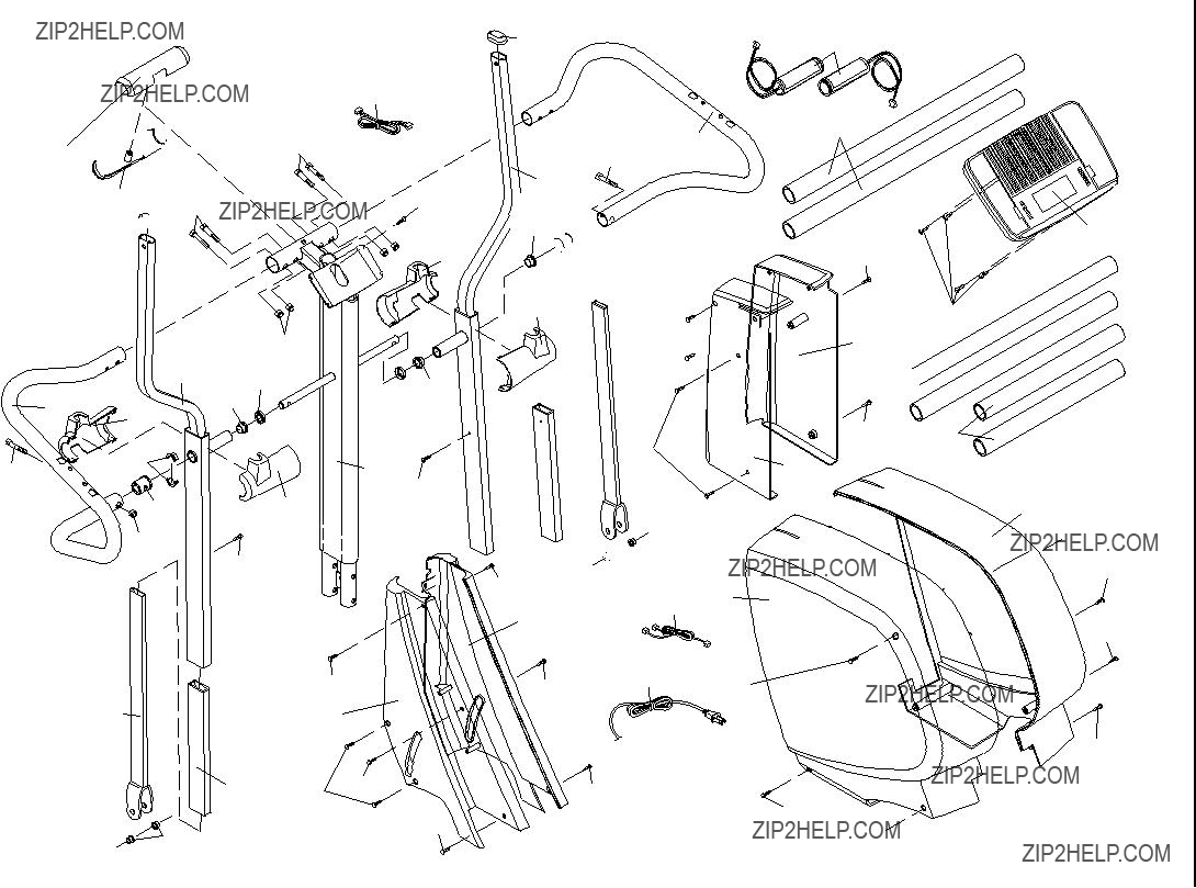
???The KEY NUMBER and DESCRIPTION of the part(s) (see pages 24 to 27)

LIMITED WARRANTY

WHAT IS COVERED???The entire NordicTrack?? elliptical exerciser (???Product???) is warranted to be free of all defects in material and workmanship.

WHO IS COVERED???The original purchaser or any person receiving the Product as a gift from the original purchaser.

HOW LONG IS IT COVERED???ICON Health & Fitness, Inc. (???ICON???), warrants the product for one year after the date of purchase. Labor is covered for one year.

WHAT WE DO TO CORRECT COVERED DEFECTS???We will ship to you, without charge, any replacement part or component, pro- viding the repairs are authorized by ICON first and are performed by an ICON trained and authorized service provider, or, at our option, we will replace the Product.

WHAT IS NOT COVERED???Any failures or damage caused by unauthorized service, misuse, accident, negligence, improper assem- bly or installation, alterations, modifications without our written authorization or by failure on your part to use, operate, and maintain as set out in your User???s Manual (???Manual???).

WHAT YOU MUST DO???Always retain proof of purchase, such as your bill of sale; store, operate, and maintain the Product as spec- ified in the Manual; notify our Customer Service Department of any defect within 10 days after discovery of the defect; as instruct- ed, return any defected part for replacement or, if necessary, the entire product, for repair.

USER???S MANUAL???It is VERY IMPORTANT THAT YOU READ THE MANUAL before operating the Product. Remember to do the periodic maintenance requirements specified in the Manual to assure proper operation and your continued satisfaction.

HOW TO GET PARTS AND SERVICE???Simply call our Customer Service Department at 1-888-825-2588 and tell them your name and address and the serial number of your Product. They will tell you how to get a part replaced, or if necessary, arrange for service where your Product is located or advise you how to ship the Product for service. Before shipping, always obtain a Return Authorization Number (RA No.) from our Customer Service Department; securely pack your Product (save the original shipping car- ton if possible); put the RA No. on the outside of the carton and insure the product. Include a letter explaining the product or prob- lem and a copy of your proof of purchase if you believe the service is covered by warranty.

ICON is not responsible or liable for indirect, special or consequential damages arising out of or in connection with the use or per- formance of the product or damages with respect to any economic loss, loss of property, loss of revenues or profits, loss of enjoy- ment or use, costs of removal, installation or other consequential damages of whatsoever nature. Some states do not allow the exclu- sion or limitation of incidental or consequential damages. Accordingly, the above limitation may not apply to you.

The warranty extended hereunder is in lieu of any and all other warranties and any implied warranties of merchantability or fitness for a particular purpose is limited in its scope and duration to the terms set forth herein. Some states do not allow limitations on how long an implied warranty lasts. Accordingly, the above limitation may not apply to you.

No one is authorized to change, modify or extend the terms of this limited warranty. This warranty gives you specific legal rights and you may have other rights which vary from state to state.

ICON HEALTH & FITNESS, INC., 1500 S. 1000 W., LOGAN, UT 84321-9813