EDGER
Model EV3850x4B
3.8 Horsepower
9 Inch Blade
Edge / Bevel Cut
Caution:
Read and follow all Safety Rules and Operating Instructions before first use of this product.
EDGER
Model EV3850x4B
3.8 Horsepower
9 Inch Blade
Edge / Bevel Cut
Caution:
Read and follow all Safety Rules and Operating Instructions before first use of this product.
TABLE OF CONTENTS
WARRANTY STATEMENT
LIMITED
For two years from the date of purchase, when this Edger is maintained, lubricated, and tuned up according to the operating and maintenance instructions in the owner???s manual, Murray will repair, free of charge, any defect in material or workmanship.
If this Edger is used for commercial or rental purposes, this warranty applies for only 90 days from the date of purchase.
This warranty does not cover the following:
SExpendable items which become worn during normal use, such as spark plugs, etc.
SRepairs necessary because of operator abuse or negligence, including bent crank shafts and the failure to maintain the equipment according to the instructions contained in the owner???s manual.
WARRANTY SERVICE IS AVAILABLE BY RETURNING THE Edger TO THE NEAREST
AUTHORIZED SERVICE CENTER IN THE UNITED STATES. THIS WARRANTY AP-
PLIES ONLY WHILE THIS PRODUCT IS IN USE IN THE UNITED STATES.
This Murray, Inc. Limited Warranty gives you specific legal rights, and you may also have other rights which vary from state to state. This Limited Warranty is given in lieu of all other expressed and implied warranties including the implied warranty of merchant- ability and warranty of fitness for a particular purpose. If you need additional informa- tion on this written warranty or assistance in obtaining service, write or call: MURRAY, INC. Customer Service Department, P.O. Box 268, Brentwood, Tennessee 37027,
Engine Exhaust, some of its constituents, and certain vehicle components contain or emit chemicals known to the State of California to cause cancer and birth defects or other repro- ductive harm.
Battery posts, terminals and related accesso- ries contain lead and lead compounds, chemi- cals known to the State of California to cause cancer and birth defects or other reproductive harm. WASH HANDS AFTER HANDLING.

SAFETY RULES
Safe Operation Practices for Edger.
WARNING: Look for this symbol to point out important safety precautions.
It means: ???Attention! Become Alert! Your Safety Is Involved.???
WARNING: To prevent acciden- tal starting when
ing repairs, always disconnect spark plug wire and put wire where it cannot contact the spark plug .
Before Use
SRead the owner???s manual carefully. Be thoroughly familiar with the controls and the proper use of the Edger. Know how to stop the Edger and disengage the controls quickly.
SDo not operate the Edger without wearing adequate outer garments. Wear footwear that will improve footing on slippery sur- faces.
SKeep the area of operation clear of all per- sons, particularly small children and pets.
SThoroughly inspect the area where the Edger is to be used and remove all foreign objects.
Fuel Safety
SHandle fuel with care; it is highly flam- mable.
SUse an approved container.
SCheck fuel supply before each use, allow- ing space for expansion as the heat of the engine and/or sun can cause fuel to ex- pand.
SFill fuel tank outdoors with extreme care. Never fill fuel tank indoors. Replace fuel tank cap securely and wipe up spilled fuel.
SNever remove the fuel tank cap or add fuel to a running or hot engine.
SNever store fuel or Edger with fuel in the tank inside a building where fumes may reach an open flame.
Operating Safety
SNever allow children or young teenagers to operate the Edger. Keep them away while it is operating. Never allow adults to oper- ate the Edger without proper instruction.
SDo not operate this machine if you are tak- ing drugs or other medication which can cause drowsiness or affect your ability to operate this machine.
SDo not use this machine if you are mentally or physically unable to operate this ma- chine safely.
SAlways wear safety glasses or eye shields during operation or while performing an adjustment or repair to protect your eyes from foreign objects that may be thrown from the Edger.
SDo not put hands or feet near or under ro- tating parts.
SExercise extreme caution when operating on or crossing gravel drives, walks, or roads. Stay alert for hidden hazards or traffic.
SExercise caution to avoid slipping or falling.
SNever operate the Edger without proper guards, plates, or other safety protective devices in place.
SNever operate the Edger at high transport speeds on slippery surfaces. Look behind and use care when backing.
SNever allow bystanders near the Edger.
SKeep children and pets away while operating.
SNever operate the Edger without good visi- bility or light.
SDo not run the engine indoors. The ex- haust fumes are dangerous, containing CARBON MONOXIDE, an ODORLESS and DEADLY GAS.
STake all possible precautions when leaving the Edger unattended. Stop the engine.
SDo not overload the Edger capacity by at- tempting to till too deep at too fast a rate.
SAFETY RULES
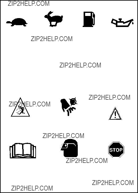
INTERNATIONAL SYMBOLS
IMPORTANT: Many of the following symbols are located on your unit or on literature sup- plied with the product. Before you operate the unit, learn and understand the purpose for each symbol.
Control And Operating Symbols
Safety Warning Symbols

1 ??? Container of Oil
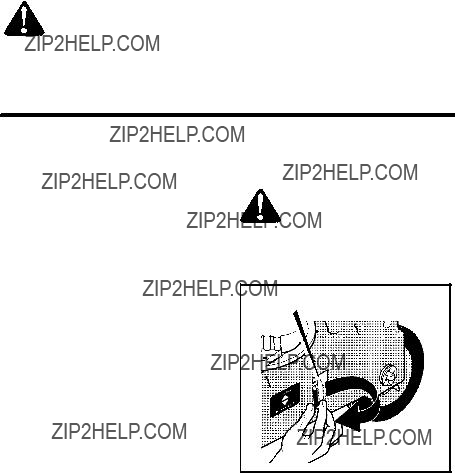
WARNING: Always wear safety glasses or eye shields while as- sembling the Edger.
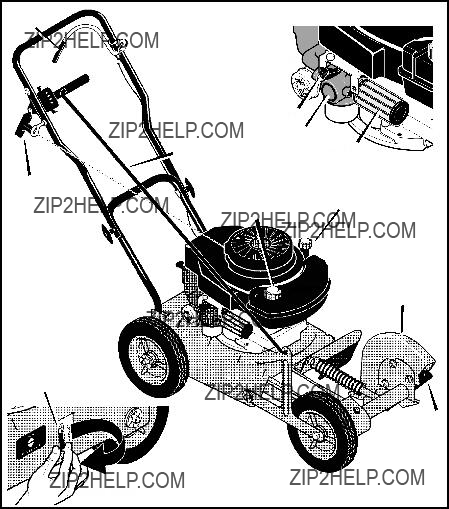
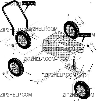
Figure 1 shows the Edger completely as- sembled.
References to the right or left side of the Edger are from the viewpoint of the opera- tor???s position behind the unit.
REMOVE THE EDGER FROM THE
CARTON
1. Remove the bottle of oil and parts bag
from the carton.
2.Cut down all four corners of the carton.
3.Remove the packing material positioned around the front and rear of the unit. Leave the packing material on the bot- tom of the unit until the control rod is as- sembled. This will keep the front wheel in a stable position.
4.Lift the Edger out of the carton and place on a hard level surface.
Figure 1
ASSEMBLY
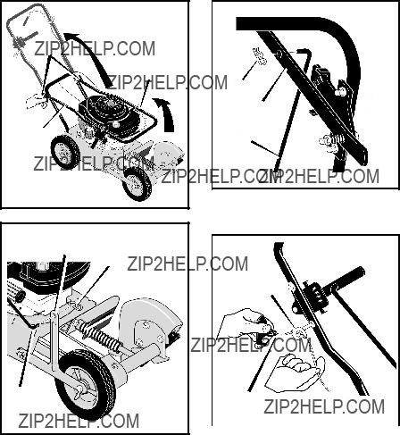
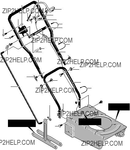
HOW TO RAISE THE HANDLE
1.Loosen the knobs and raise the upper handle to the upright position. See Figure 2.
2.Tighten the knobs. Make sure the knobs are to the outside of the handles as shown in Figure 2.
3.Insert the end of the control rod, from RIGHT to LEFT, through the hole in the front wheel arm. Attach with hair pin found in parts bag. See Figure 3.
4.Push down on the handle to tilt the unit back.
Knobs
Upper
Handle
Control
Rod
Figure 2
Front
Wheel Arm
Hair Pin
5.Insert the other end of the control rod, from RIGHT to LEFT, through the hole in the depth control lever and fasten with hair pin. See Figure 4.
6.Move the depth control lever forward to the STARTING and TRANSPORT posi- tion.
7.Remove any packing material from the bottom of the unit.
8.To attach the recoil starter rope to the rope guide, twist the recoil starter rope through the rope guide. See Figure 5.
Hairpin
Depth Control
Lever
Control Rod
Figure 4
Rope Guide

ASSEMBLY
HOW TO PREPARE THE ENGINE
ENGINE DOES NOT CONTAIN
OIL OR GASOLINE
See the engine manufacturer???s instructions for the type of gasoline and oil to use. Before you use the unit, read the information on safety, operation, maintenance, and storage. This Edger was shipped with a 20 ounce container of SAE30 motor oil. Add this oil to the engine before operating. To fill the crank- case, remove the oil fill cap/dipstick and add the SAE30 motor oil. DO NOT OVERFILL.
NOTE: The engine may contain a small amount of oil. When adding oil, frequently insert the oil fill cap/dipstick and check the amount of oil in the engine. DO NOT
OVERFILL.
WARNING: Follow the engine manufacturer???s instructions for the type of gasoline and oil to
use. Always use a safety gasoline con- tainer. Do not smoke when adding gaso- line to the engine. When inside an en- closure, do not fill with gasoline. Before you add gasoline, stop the engine. Let the engine cool for several minutes.
IMPORTANT: This unit is equipped with an internal combustion engine and must not be used on or near any unimproved forest??? covered,
In the State of California the above is re- quired by law (Section 4442 of the Califor- nia Public Resources Code). Other states may have similar laws. Federal laws apply on federal lands. See an Authorized Ser- vice Center for a spark arrester for the muf- fler.
n CHECKLIST
For the best performance and satisfaction from this quality product, please review the following checklist before you operate the Edger:
nAll assembly instructions have been completed.
nCheck carton. Make sure no loose parts remain in the carton.
nAll fasteners have been properly tight- ened.
As you learn how to use the Edger, pay extra attention to the following important items:
nn Engine oil is at proper level.
nnFuel tank is filled with a fresh, clean, regular Unleaded gasoline.
nnBecome familiar and understand the function of all controls. Before your start the engine, operate all controls.
OPERATION
KNOW YOUR EDGER
READ THE OWNER???S MANUAL AND ALL SAFETY RULES BEFORE YOU OPERATE the Edger. To familiarize yourself with the location of the controls, compare the illustrations with your Edger. Save this manual for future reference.
Engine Stop
Lever
 Depth Control Lever
Throttle Control
Recoil
Starter
HandleFuel Tank Oil Fill Cap
Cap
Blade Guard
Index Lever
(Located On Left
Side Of Edger)
 Blade
Blade
Blade Guide
Figure 6
OPERATION
EYE PROTECTION
Always wear safety glasses. If you wear eye glasses, put a Wide Vision Safety Mask over your eye glasses.
WARNING: Debris thrown from the Edger can result in foreign objects being thrown into the
eyes, which can cause severe eye dam- age. Always wear safety glasses or eye shields when operating the Edger.
HOW TO USE THE INDEX LEVER
Bevel edging cuts a trench and reduces the need to edge as often.
1.Stop the engine and disconnect the spark plug wire from the spark plug.
2.Disengage the index lever from the EDGING position and move to the BEVEL position.
3.Reconnect the spark plug wire to the spark plug.
4.Start the engine.
5.Move the depth control lever to the de- sired height.
NOTE: For deep edging, first cut at shal- low depths. Then, cut at greater depths until the desired depth is obtained.
WARNING: While the engine is running, never leave the Edger. Before you adjust the wheels or
change the blade position, always dis- engage the cutting blade and stop the engine.
Index Lever
Figure 7
OPERATION
WARNING: When the engine runs, the blade will rotate. To prevent injury, keep hands and
feet away from blade.
HOW TO STOP THE EDGER
1.Move the depth control lever forward to raise the blade. Then, release the engine stop lever. See Figure 8.
WARNING: Never leave the Edger unattended while the en- gine is running. Always raise
the cutting blade and stop the engine.
HOW TO USE
THE DEPTH CONTROL LEVER
1.Start the engine.
2.To lower the cutting blade, pull the depth control lever back.
3.Select the edging depth that you need. There are three selections with an approximately depth of two inches.
NOTE: For deep edging, first cut at shal- low depths. Then, cut at greater depths until the desired depth is obtained.
HOW TO USE
THE ENGINE STOP LEVER
1.Release the engine stop lever and the engine and the blade will automatically stop. To run the engine, hold the engine stop lever in the operating position. See Figure 8.
2.If the engine continues to run, move the throttle control to the STOP position (see Figure 9).
IMPORTANT: Before you start the engine, operate the engine stop lever several times. Make sure the engine stop cable moves freely. If the engine stop cable is bent or damaged, replace the cable. If the problem continues, take the Edger to an Authorized Service Center to correct the problem.
Engine Stop Lever
(Operating Position)
 Depth
Depth
Control
Lever
Figure 8
HOW TO USE
THE PRIMER BUTTON
When starting a cold engine, push the prim- er button five times (see Figure 9). Wait approximately two seconds between each push.
IMPORTANT: When starting a warm en- gine, do not use the primer button.
HOW TO USE
THE THROTTLE CONTROL
1.The engine is designed to operate at full speed. The throttle control has only two
positions, RUN and STOP. When operat-
ing, the throttle control must be in the RUN position. (see Figure 9).
Throttle
Control

OPERATION

OPERATION
EDGING TIPS
SEdging is best performed when conditions are dry. If the soil is to wet, dirt becomes packed around the blade causing prema- ture belt wear and decreased perfor- mance.
SIf dirt does become packed around the blade, stop the engine and remove the wire from the spark plug. Remove the packed dirt and debris from the blade.
SFor deep edging, first cut at shallow depths. Then, cut at greater depths until the desired depth is obtained.
SFor uniform edging, make sure the blade guide rides on the surface.
SEdging can be customized by varying the number of passes and by the distance the blade is from the surface.
WARNING: Read the Owner???s manual. Know location and functions of all controls. Keep
all safety devices and shields in place. Never allow children or uninstructed adults to operate Edger. Shut off engine before unclogging blade or making re- pairs. Keep bystanders away from ma- chine. Keep away from the blade all ro- tating parts, which cause injury.

MAINTENANCE
CUSTOMER RESPONSIBILITIES
GENERAL RECOMMENDATIONS
The warranty on this Edger does not cover items that have been subjected to operator abuse or negligence. To receive full value from the warranty, the operator must main- tain the Edger as instructed in this manual.
ENGINE MAINTENANCE
Use the following maintenance section to keep your unit in good operating condition. All the maintenance information for the en- gine is in the ???Engine Instruction Book???. Be- fore you start the engine, read this book.
Some adjustments must be made periodical- ly to properly maintain your Edger.
All adjustments in the Service and Adjust- ments section of this manual must be checked at least once each season.
LUBRICATION
1.After each 25 hours, apply a small amount of engine oil to all moving parts, particular- ly the wheels.
2.To lubricate the engine, refer to the ???En- gine Instruction Book???.

SERVICE AND ADJUSTMENT
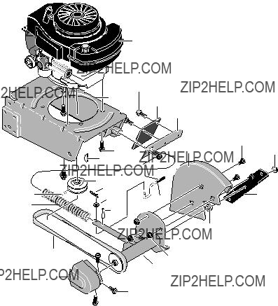
HOW TO REMOVE THE BELT
The belt made of a special compound. If the belt becomes worn or breaks, replace the belt with an original equipment belt.
1.Disconnect the spark plug wire from the spark plug.
2.Drain the gasoline and oil from the en- gine.
3.Tip the Edger backwards on the handle. Block the top of the handle against a wall or under a bench.
4.Remove the screws from the belt guard (see Figure 11).
Belt
Screw
Screw
Belt Guard
Figure 11
5.To compress the spring and release ten- sion on the belt, push the blade bearing housing back toward the engine (see Figure 12).
6.Carefully note the twist of the belt around the engine pulley. Remove the old belt. Replace with an original equipment belt.
7.To install a new belt, reverse the above steps. Make sure to twist the new belt as shown in Figure 12.
NOTE: If the belt is not installed properly, the blade will not turn in the proper direc- tion and can damage the blade or belt.
Engine Pulley Blade Housing Bearing
Spring
Note Direction
Of Twist
Figure 12
SERVICE AND ADJUSTMENT
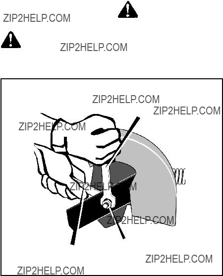
HOW TO REPLACE THE BLADE
The blade is subject to wear and damage, such as nicks and dents. This will not gener- ally affect its function.
1.Disconnect the spark plug wire from the spark plug.
The blade is designed to not require sharp- ening. Do not attempt to sharpen the blade. The blade is also reversible. If nicks or dents are excessive, remove the blade and turn it around. This will provide a fresh cut- ting edge. Replace the blade if both sides are worn or damaged.
WARNING: Do not sharpen the blade. Sharpening can damage the blade and cause it to break,
which can cause injury to yourself or to others.
To replace the blade, follow the steps below.
2.Remove the blade locknut that holds the blade to the drive shaft.
WARNING: To remove or tigh- ten the blade locknut, always use the method shown in
Figure 13. Always position the holding wrench on the nut behind the blade.
3.Remove the blade.
4.Install a new blade and blade locknut. Tighten the blade locknut to a torque of
Turn Wrench
To Tighten Locknut
Blade Locknut
Hold Nut,
Do Not Turn
Figure 13

SERVICE AND ADJUSTMENT
STORAGE
WARNING: Never store the Edger indoors with fuel in the fuel tank. Never store in an en-
closed, poorly ventilated area where fumes could reach an open flame, a spark or a pilot light as on a furnace, wa- ter heater or clothes dryer.
WARNING: Do not remove gas- oline while inside a building, near a fire, or while you smoke.
Gasoline fumes can cause an explosion or a fire.
When the Edger is put in storage for thirty days or more, follow the steps below to make sure the Edger is in good condition the following season.
1.Drain the fuel tank.
2.Let the engine run until it is out of gaso- line.
3.Drain the oil from the warm engine. Fill the engine crankcase with new oil.
4.Remove the spark plug from the cylin- der. Pour one ounce of oil into the cylin-
der. Slowly pull the
5.Clean the dirt and debris from the cylin- der cooling fins and the engine housing.
6.Completely clean the Edger.
7.Check the Edger for worn or damaged parts. Tighten all loose hardware.
8.Apply a small amount of engine oil to all moving parts, particularly the wheels.
9.Put the unit in a building that has good ventilation.
10.Cover the Edger with a suitable protec- tive cover that does not retain moisture. Do not use plastic.
IMPORTANT: Never cover the Edger while the engine and exhaust areas are still warm.
NOTE: A yearly checkup or
TROUBLE SHOOTING CHART
MODEL EV3850x4B
10
MODEL EV3850x4B
418
343712C
MODEL EV3850x4B
MODEL EV3850x4B
103
NOTES
HOW TO ORDER REPAIR PARTS
Only use a factory repair part. Repair parts, except for the engine or the transmission, are available from the store where the unit was purchased, a service shop recommended by the store, or an authorized service shop found in the yellow pages of the telephone directory. If you cannot get a repair part or service as described above, call or write to the Central Parts Distributor shown below. When you order, include the following information: (1) Complete Model Number (see nameplate), (2) Date of Manufacture, (3) Complete Part Number, (4) Description, (5) Quantity.
Repair parts for the engine or the transmission are available from the manufacturer's authorized service center found in the yellow pages of the telephone directory. See the individual engine or transmission warranties.
MURRAY, INC. LAWN MOWER CENTRAL PARTS DISTRIBUTORS
BILLIOU'S, INC.
1343 South Main St.
Porterville, CA. 93257
Arizona, California, Hawaii,
Nevada
BROWN & WISER, INC.
9991 S.W. Avery Street Tualatin, OR. 97062
Alaska, Idaho (counties Ada, Adams, Benewah, Boise, Bonner, Boundry, Canyon, Clearwater, Elmore, Gem, Idaho, Kooten, Latah, Lewis, NEZ Perce, Owyee, Payette, Ravalli, Shoshone, Valley, Washington), Montana (counties Flathead, Lake, Lincoln, Mineral, Missoulo, Ravalli, Sanders),
Oregon, Washington
CPT CANADA POWER
TECHNOLOGY LIMITED
Mississauga
161 Watline Avenue
Mississauga, Ontario
Edmonton
Ville St4Laurent
234 Migneron Street Ville
Canada
FRANK EDWARDS CO.
3626 Parkway Blvd.
West Valley City, UT 84120
FAX
Colorado, Idaho (counties Bannock Bearlake, Bingham, Blaine, Booneville, Butte, Camas, Caribou, Cassia, Custer, Franklin, Fremont, Gooding, Jefferson, Jerome, Lemhi, Lincoln, Madison, Minidoka, Oneida, Power, Teton, Twin Falls) Montana (all counties except Flathead, Lake, Lincoln, Mineral, Missoulo, Ravalli, Sanders), Utah, Wyoming
GARDNER, INC.
1150 Chesapeake Ave.
Columbus, OH. 43212
Alabama, Arkansas, (except these counties: Hempstead, Howard, Lafayette, Little River, Miller, Nevada, Pike, Sevier),
Connecticut, Delaware, District of Columbia, Florida, Georgia, Illinois (South of Hwy. 80),
Indiana, Iowa, Kansas, Kentucky, Main, Maryland, Massachusetts, Michigan (except upper Peninsula), Mississippi, Missouri, Nebraska, New Hampshire, New Jersey, New York, North Carolina, Ohio, Pennsylvania, Rhode Island, South Carolina, Tennessee, Vermont, Virgina, West Virginia
Puerto Rico
GULF COAST ENGINE, INC.
4202 Russell Dr.
Corpus Christi, TX. 78408
FAX
Arkansas (counties Hempstead, Howard, Lafayette, Little River, Miller, Nevada, Pike, Sevier) New Mexico, Oklahoma, Texas, Mexico
WISCONSIN MAGNETO
4727 N. Teutonia Ave. Milwaukee, WI. 53209
Illinois (N. of Hwy. 80), Michigan
(upper Peninsula), Minnesota,
North Dakota, South Dakota,
Wisconsin