Symbol MiniScan MSXX07 Series
Integration Guide
Symbol MiniScan MSXX07 Series
Integration Guide
Symbol MiniScan MSXX07 Series
Integration Guide
Revision A
May 2008

ii Symbol MiniScan MSXX07 Series Integration Guide
?? 2008 by Motorola, Inc. All rights reserved.
No part of this publication may be reproduced or used in any form, or by any electrical or mechanical means, without permission in writing from Motorola. This includes electronic or mechanical means, such as photocopying, recording, or information storage and retrieval systems. The material in this manual is subject to change without notice.
The software is provided strictly on an ???as is??? basis. All software, including firmware, furnished to the user is on a licensed basis. Motorola grants to the user a
Motorola reserves the right to make changes to any software or product to improve reliability, function, or design.
Motorola does not assume any product liability arising out of, or in connection with, the application or use of any product, circuit, or application described herein.
No license is granted, either expressly or by implication, estoppel, or otherwise under any Motorola, Inc., intellectual property rights. An implied license only exists for equipment, circuits, and subsystems contained in Motorola products.
MOTOROLA and the Stylized M Logo and Symbol and the Symbol logo are registered in the US Patent & Trademark Office. Bluetooth is a registered trademark of Bluetooth SIG. Microsoft, Windows and ActiveSync are either registered trademarks or trademarks of Microsoft Corporation. All other product or service names are the property of their respective owners.
Motorola, Inc.
One Motorola Plaza
Holtsville, New York
Patents
This product is covered by one or more of the patents listed on the website: http://www.symbol.com/patents.
Warranty
For the complete Motorola hardware product warranty statement, go to: http://www.symbol.com/warranty.

iii
Revision History
Changes to the original manual are listed below:

iv Symbol MiniScan MSXX07 Series Integration Guide

Table of Contents

vi Symbol MiniScan MSXX07 Series Integration Guide

viii Symbol MiniScan MSXX07 Series Integration Guide

x Symbol MiniScan MSXX07 Series Integration Guide

xii Symbol MiniScan MSXX07 Series Integration Guide

About This Guide
The Symbol MiniScan MSXX07 Series Integration Guide provides general instructions for mounting, setting up, and programming the following MiniScan models:
???MS1207FZY
???MS1207WA
???MS2207
???MS2207VHD
???MS3207.
NOTE It is recommended that an
Chapter Descriptions
Topics covered in this guide are as follows:
???Chapter 1, Getting Started provides an overview of the MiniScan scanners and features, and provides a block diagram of the scanner.
???Chapter 2, Installation describes how to mount and install the MiniScan scanner.
???Chapter 3, Scanning provides information on scan patterns, scanning, triggering options, and beeper and LED definitions.
???Chapter 4, Symbol MS1207FZY Specifications provides the technical and scanning specifications for the Symbol MS1207FZY scanner.
???Chapter 5, Symbol MS1207WA Specifications provides the technical and scanning specifications for the Symbol MS1207WA scanner.
???Chapter 6, Symbol MS2207 Specifications provides the technical and scanning specifications for the Symbol MS2207 scanner.
xivSymbol MiniScan MSXX07 Series Integration Guide
???Chapter 7, Symbol MS2207VHD Specifications provides the technical and scanning specifications for the Symbol MS2207VHD scanner.
???Chapter 8, Symbol MS3207 Specifications provides the technical and scanning specifications for the Symbol MS3207 scanner.
???Chapter 9, Maintenance and Troubleshooting provides information on maintaining and troubleshooting the MiniScan scanners.
???Chapter 10, Parameter Menus describes the programmable parameters and provides bar codes for programming.
???Chapter 11,
???Chapter 12, USB Interface describes how to set up the scanner for USB operation.
???Chapter 13, Advanced Data Formatting (ADF) describes how to customize scanned data before transmitting to the host.
???Chapter 14, Mounting Template provides mounting templates for the MiniScan scanners.
???Appendix A, ASCII Character Sets provides prefix and suffix values to assign for ASCII character data transmission.
Notational Conventions
The following conventions are used in this document:
???Italics are used to highlight chapters and sections in this and related documents.
???bullets (???) indicate:
???Action items
???Lists of alternatives
???Lists of required steps that are not necessarily sequential
???Sequential lists (e.g., those that describe
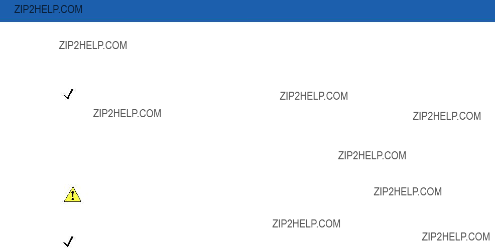
NOTE This symbol indicates something of special interest or importance to the reader. Failure to read the note will not result in physical harm to the reader, equipment or data.
CAUTION This symbol indicates that if this information is ignored, the possiblity of data or material damage may occur.
WARNING! This symbol indicates that if this information is ignored the possibility that serious personal injury may occur.

Related Documents
The following document provides more information for MiniScan Series scanners.
???MiniScan Family of Scanners Quick Reference Guide, p/n
For the latest version of this guide and all guides, go to: http://www.symbol.com/manuals.
Service Information
If you have a problem with your equipment, contact Motorola Enterprise Mobility Support for your region. Contact information is available at: http://www.symbol.com/contactsupport.
When contacting Enterprise Mobility Support, please have the following information available:
???Serial number of the unit
???Model number or product name
???Software type and version number.
Motorola responds to calls by
If your problem cannot be solved by Motorola Enterprise Mobility Support, you may need to return your equipment for servicing and will be given specific directions. Motorola is not responsible for any damages incurred during shipment if the approved shipping container is not used. Shipping the units improperly can possibly void the warranty.
If you purchased your Enterprise Mobility business product from a Motorola business partner, contact that business partner for support.

xvi Symbol MiniScan MSXX07 Series Integration Guide
Chapter 1 Getting Started
CAUTION Use of controls, adjustments or procedures other than those specified here can result in hazardous laser light exposure.
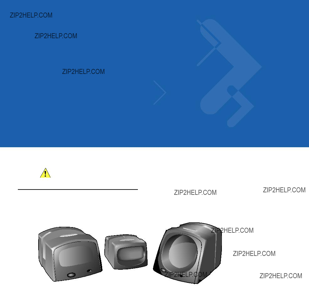
Introduction
The MiniScan family of industrial
Figure
Symbol MSXX07 Series scanners provide easy and flexible integration of bar code scanning into a host device, and include the following models:
???The Symbol MS1207FZY offers fuzzy logic for premium scanning performance on all types of 1D bar codes including poorly printed and low contrast symbols. The MS1207FZY features a compact design for superior performance and durability in a form factor that easily integrates into OEM devices for embedded applications such as medical instruments, diagnostic equipment, vending machines, and gaming. As a
???The Symbol MS1207WA Wide Angle Scanner features a broad 60o scan angle to accommodate large 1D bar codes within extremely close range. This scanner is ideal for

1 - 2 Symbol MiniScan MSXX07 Series Integration Guide
???The Symbol MS2207 and MS2207VHD offer a "smart" raster pattern optimized for 2D applications and poorly printed 1D bar codes. The high scan rate ensures fast and reliable data on all 1D symbols, and 2D codes such as PDF417, MicroPDF, GS1 DataBar and composite codes. These scanners are perfect for automated data entry applications that require
???The Symbol MS3207 features a
Symbol MSXX07 Series Features
???
???Quick and easy integration for OEM devices
???Excellent scanning performance on all types of bar codes (MS1207FZY and MS1207WA support 1D bar codes only)
???Rugged IP54 sealed housing with integrated beeper
???
???Easy programming and configuration
???Flexible mounting options
???LEDs and an integrated beeper indicating scanner power status and successful decodes.
Typical Applications
MiniScan is the perfect solution for the following applications:
Fixed Mount Standalone Applications
???Manufacturing / warehouse
???Conveyer belts
???Security / ID verification
???POS
???Library tracking
???Document control.
OEM Applications
???Kiosks / ATMs
???Music listening stations
???Security / ID verification
???Lottery terminals / gaming.
Block Diagram
The MiniScan block diagram illustrates the functional relationship of the MiniScan components. Following is a detailed description of each component in the block diagram.
Figure
Miniscan Block Diagram Descriptions
Decoded Scan Engine - The scan engine emits a beam of laser light that reflects off the bar code. Black bars absorb light, white spaces reflect light. The scan engine collects the reflected light and processes the signal through several analog filters. The filtered signal is digitized into a Digitized Barcode Pattern (DBP). The decoder
Interface Board - The interface board adapts the scan engine's interface into usable signals and data for the intended host. It also contains a beeper and red/green LED for audio/visual feedback, and provides for an external trigger and external beeper.
The interface board converts the scan engine's data to Synapse, USB, or TTL level
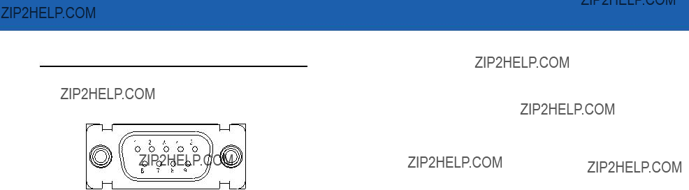
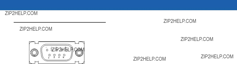
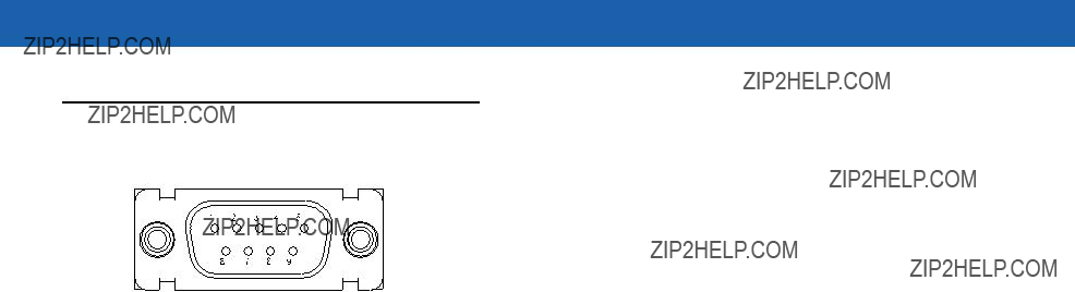
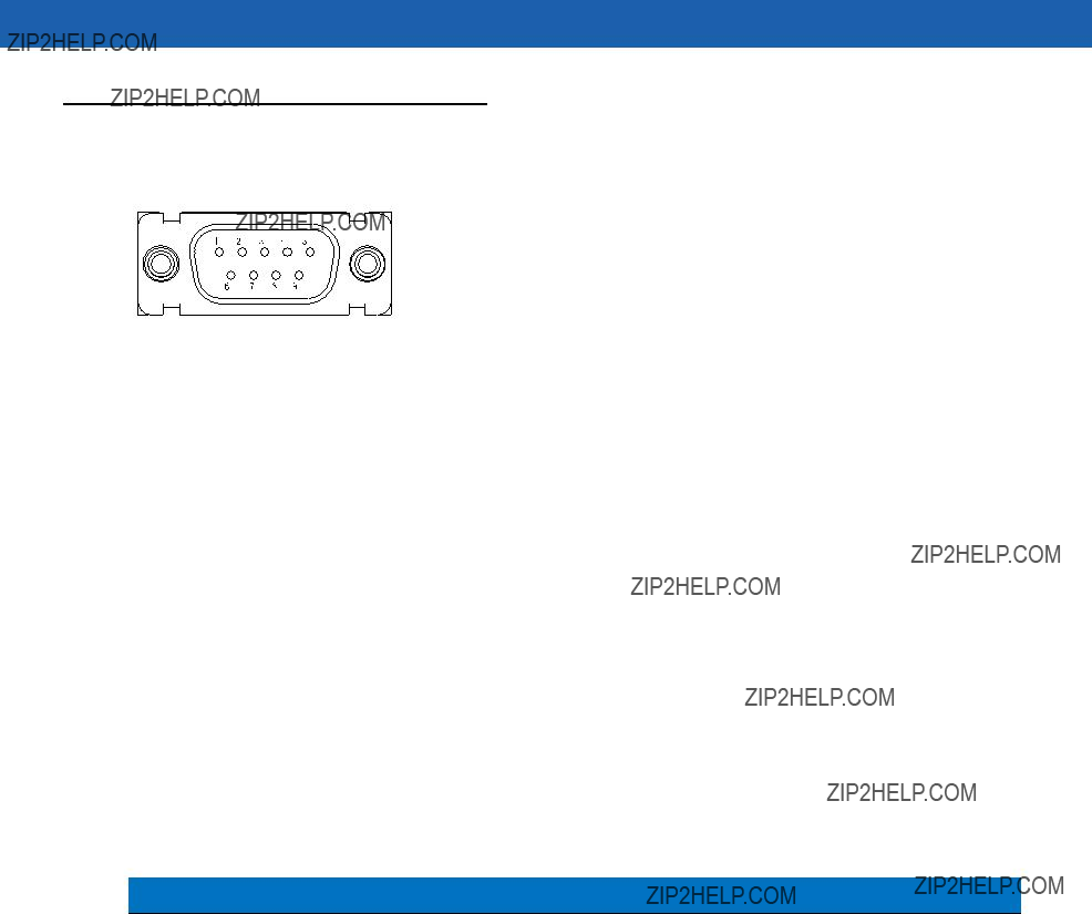
DB9 - The DB9 connector provides a sealed outlet for the various interface signals used between a MiniScan scanner and the host. It also maintains pin compatibility with the previous generation LS1220 MiniScan host cables.

1 - 4 Symbol MiniScan MSXX07 Series Integration Guide

Chapter 2 Installation
Introduction
This chapter provides information on unpacking, mounting, and installing the MiniScan.
Unpacking
Remove the MiniScan from its packing and inspect for damage. If the scanner is damaged, contact Motorola Enterprise Mobility Support. See page xv for contact information.
KEEP THE PACKING. It is the approved shipping container and should be used if the equipment needs to be returned for servicing.
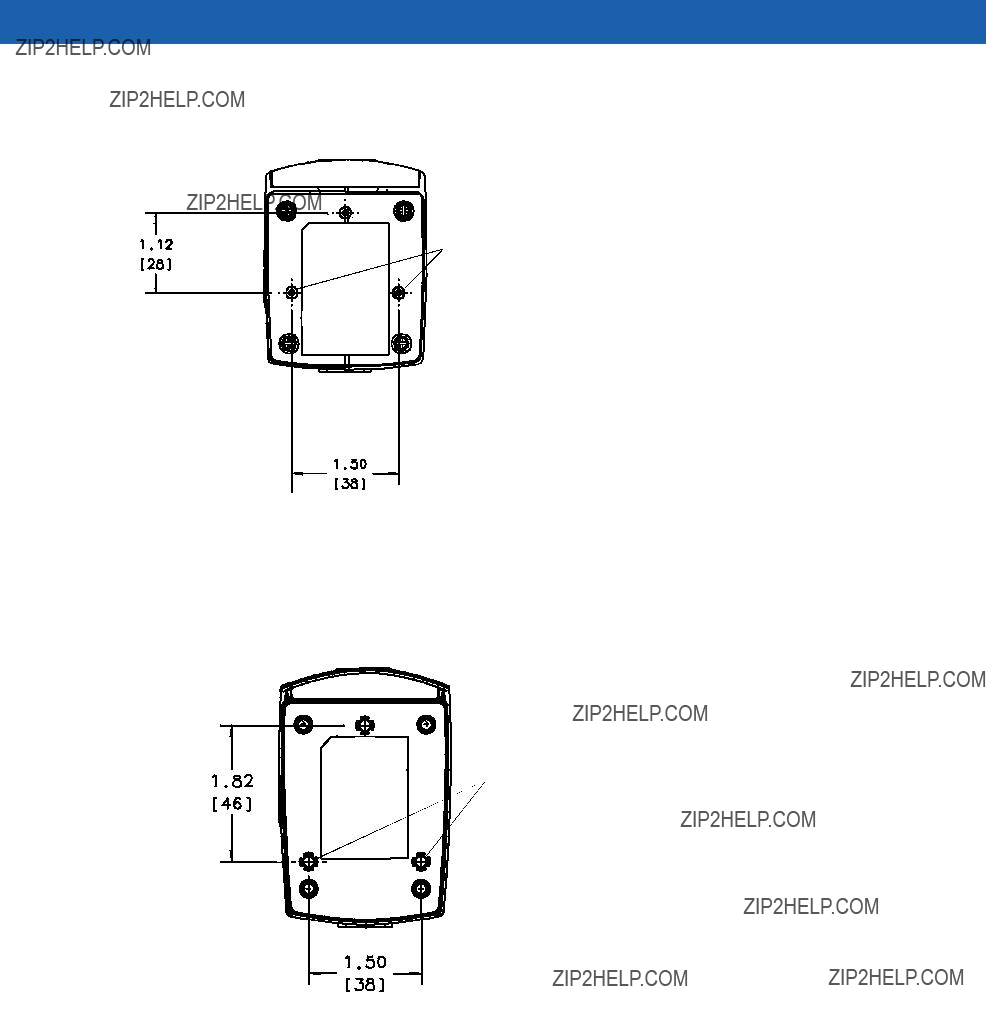
Mounting
There are three mounting holes (threaded inserts) on the bottom of the chassis.
The following figures provide mounting dimensions for the MiniScan scanner housings. For a mounting template, see Mounting Template on page
NOTE Use only
2 - 2 Symbol MiniScan MSXX07 Series Integration Guide
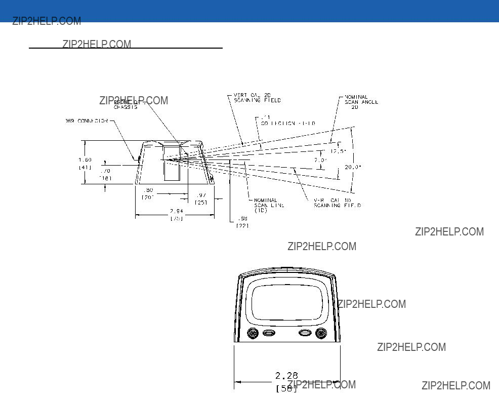
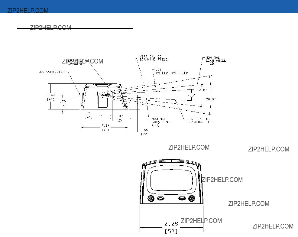
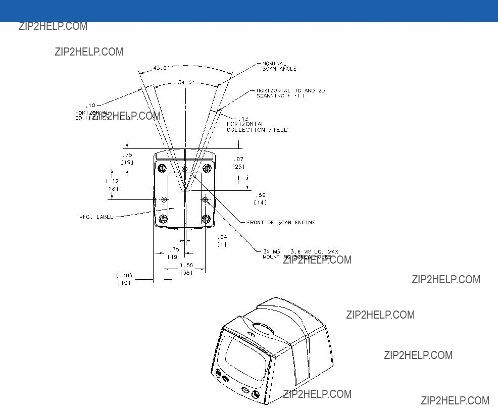
Symbol MS1207FZY/MS1207WA/MS2207/MS2207VHD Mounting Dimensions
 Threaded Inserts
Note:
Dimensions are in inches [mm].
Figure
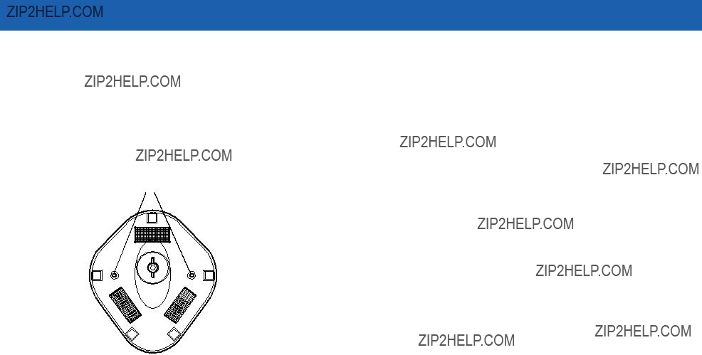
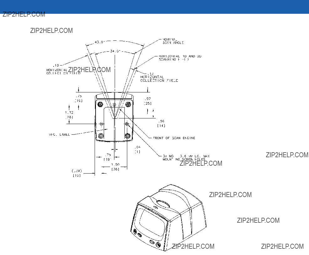
Symbol MS3207 Mounting Dimensions
 Threaded Inserts
Note:
Dimensions are in inches [mm].
Figure

Installation 2 - 3
Mounting the Scanner on the Optional Stand
To mount the scanner on the optional stand:
1.Place the bottom of the scanner on the stand???s scanner mount, aligning the scanner???s center threaded insert (beneath the scan window) with the center mounting hole on the front of the stand. The two rear threaded inserts on the bottom of the scanner align with the proper mounting holes on the stand.
2.Secure the scanner to the stand using the three screws provided with the stand.
Assembling the Stand
Scanner mount 

Mounting holes
Flat areas 
Stand base
Wingnut 

Figure
1.Unscrew the wingnut from the bottom of the
2.Fit the bottom of the neck piece into the opening on the top of the stand base.
3.Tighten the wingnut underneath the base to secure the cup and neck piece (see the note below).
4.Bend the neck to the desired position for scanning.
NOTE Before tightening the wingnut under the base, ensure that the flat areas on the flexible neck fit securely in the grooves in the base.
Mounting the Stand (optional)
You can attach the base of the scanner???s stand to a flat surface using two screws or
Screw Mount
1.Position the assembled base on a flat surface.
2.Screw one #10 wood screw into each
2 - 4 Symbol MiniScan MSXX07 Series Integration Guide
Tape Mount
1.Peel the paper liner off one side of each piece of tape and place the sticky surface over each of the three rectangular tape areas.
2.Peel the paper liner off the exposed sides of each piece of tape and press the stand on a flat surface until it is secure.
Two

 Double-sided
areas (3 places) (dimensions = 1??? x 2???)
Figure
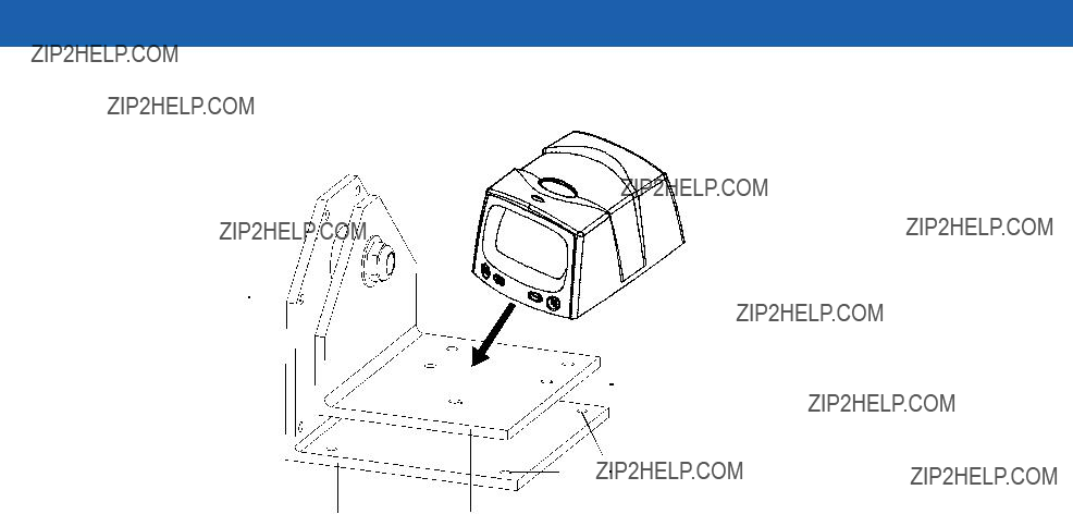
Mounting the Scanner on the Optional Mounting Bracket
The optional mounting bracket kit consists of a scanner bracket, a mounting bracket, and the hardware required to mount the scanner. The bracket kit accommodates adjustable angles for optimal positioning of the scanner.
To mount the MiniScan scanner on the bracket, first secure the scanner to the scanner bracket, then attach the mounting bracket to the wall (see Figure
1.Tilt the scanner bracket forward to access the center scanner mounting hole on the bracket.
2.Place the bottom of the scanner on the scanner bracket, aligning the scanner???s center threaded insert (beneath the scan window) with the center mounting hole on the scanner bracket.
3.Insert one of the screws provided through the mounting hole and into the scanner???s center threaded insert.
For the Symbol MS1207FZY, MS1207WA, MS2207, and MS2207VHD, use a #0 Phillips screwdriver; for the Symbol MS3207, use a #1 Phillips screwdriver.
4.Tilt the scanner bracket in the opposite direction to access the rear scanner mounting holes (which are aligned with the rear inserts on the bottom of the scanner), then insert the remaining two screws provided through the two rear mounting holes and into the scanner???s threaded inserts.
5.Secure the mounting bracket to a flat surface by inserting 1/8??? or smaller fasteners through the surface and into the bracket???s mounting holes. There are four mounting holes on the bottom of the mounting bracket for horizontal mounting, and six holes on the side for vertical mounting.
Installation 2 - 5
Vertical
Mounting Holes
 Scanner
Mounting Holes
Horizontal
Mounting Holes
Figure
2 - 6 Symbol MiniScan MSXX07 Series Integration Guide
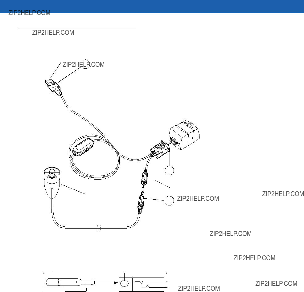
Connecting the MiniScan
To connect the MiniScan to the host, connect the scanner cables in the order shown in Figure
To Host
3
Beeper (Optional)
Figure
2
3
3
soldering leads.
Figure
Installation 2 - 7
Connecting the Symbol MSXX07 via USB
Using a PC running Microsoft Windows:
1.Connect the USB cable to the USB port on the host.
2.Connect the other end of the USB cable to the scanner as indicated on the cable. The scanner powers up and beeps.
3.On the host, open a word processing program such as Microsoft Word.
4.Present a bar code to the scanner. A beep indicates a decode, and the data appears on the host screen.
Location and Positioning
CAUTION The location and positioning guidelines provided do not consider unique application characteristics. Motorola recommends that an
NOTE Integrate the scanner in an environment no more extreme than the product???s specification, where the scanner will not exceed its temperature range. For instance, do not mount the scanner onto or next to a large heat source. When placing the scanner with another device, ensure there is proper convection or venting for heat. Follow these suggestions to ensure product longevity, warranty, and overall satisfaction with the scanner.
Using the MiniScan as an Embedded Scanner
You can mount the MiniScan read symbols that are automatically presented, or that are presented in a
Two methods of positioning the scanner are provided:
???Use the Calculating the Usable Scan Length Method on page
???The Testing the Usable Scan Length Method on page
2 - 8 Symbol MiniScan MSXX07 Series Integration Guide
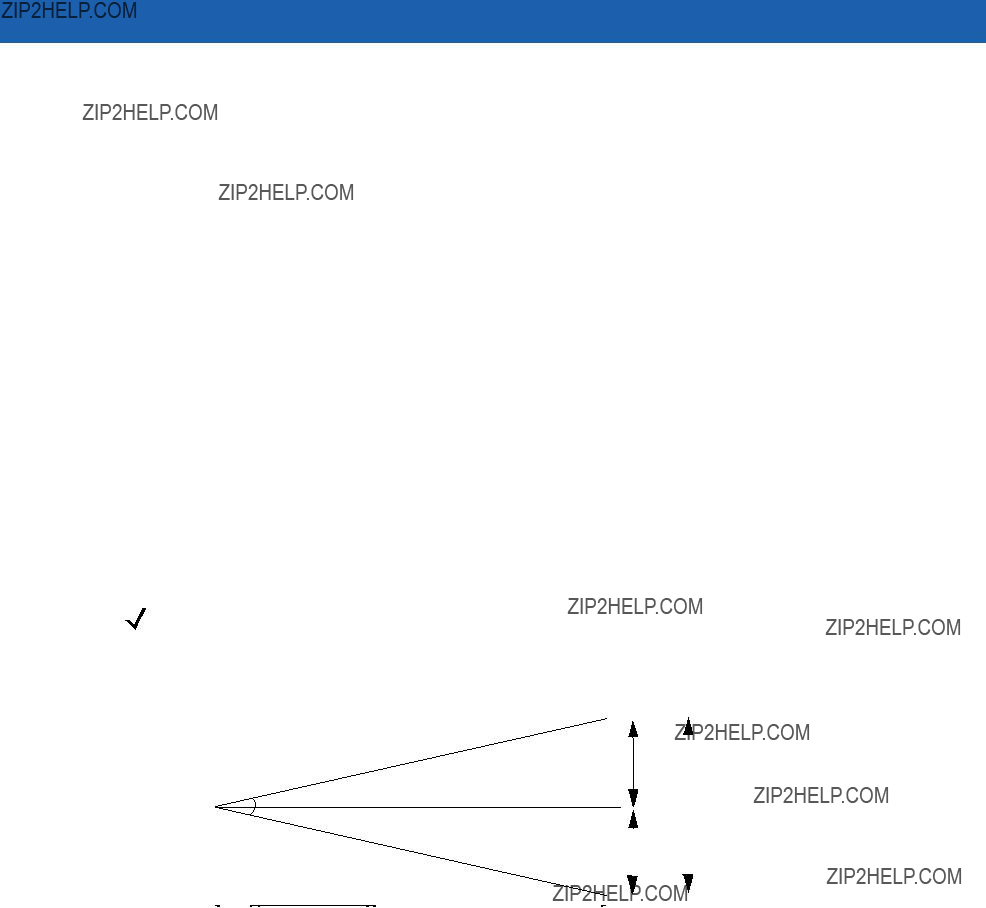
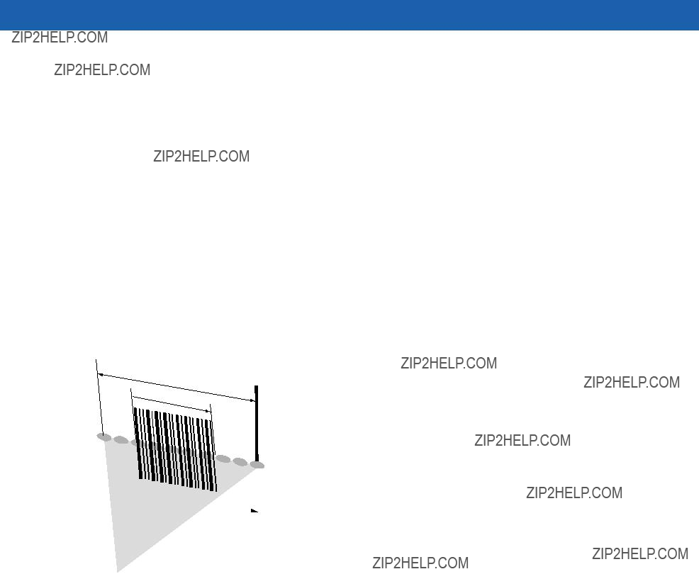
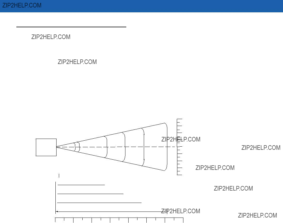
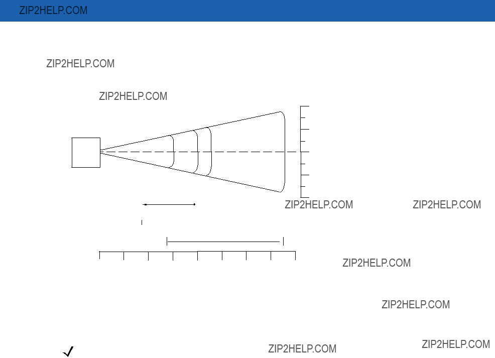
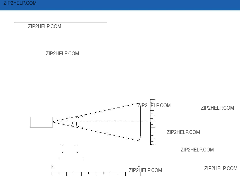
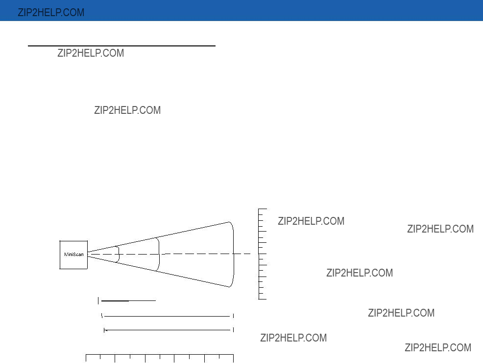
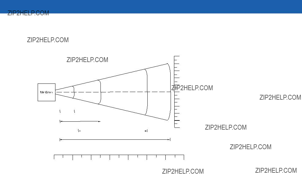
Calculating the Usable Scan Length Method
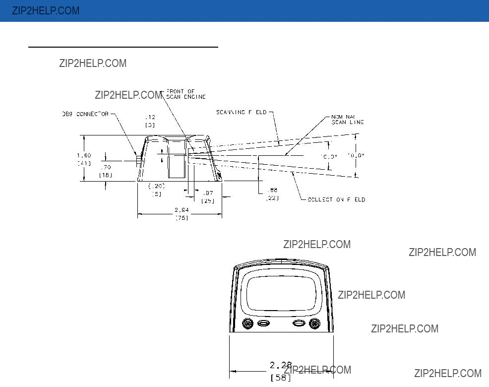
Calculate usable scan length as follows (see Figure
L = 1.8 x (D+d+B) x Tan (A/2)
Table
D = Distance (in inches) from the front edge of the host housing to the bar code.
d = The host housing???s internal optical path from the edge of the housing to the front of the MiniScan scanner. B = Internal optical path from the scan mirror to the front edge of the MiniScan scanner.
A = Scan angle in degrees.
NOTE Usable scan length determined by this formula, or 90% of scan line at any working distance. This formula is based on good quality symbols in the center of the working range and length of bar code.
Figure
Installation 2 - 9
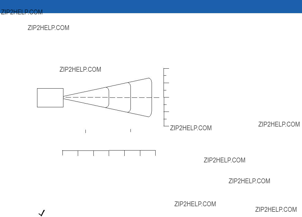
Testing the Usable Scan Length Method
Due to the variety of symbol sizes, densities, print quality, etc., there is no simple way to calculate the ideal symbol distance. To optimize performance, use the Testing The Usable Scan Length positioning method:
1.Measure the maximum and minimum distances at which the symbols can be read.
2.Check the near and far range on several symbols. If they are not reasonably consistent there may be a printing quality problem that can degrade the performance of the system. Motorola can provide advice on how to improve the installation.
NOTE Poor quality symbols (from bad printing, wear, or damage) may not decode well when placed in the center of the depth of field (especially higher density codes). The scan beam has a minimum width in the central area, and when the scanner tries to read all symbol imperfections in this area it may not decode. After a preliminary spot is determined using good quality symbols, test several reduced quality symbols and adjust the spot for the best overall symbol position.
3.Locate the scanner so the symbol is near the middle of the near/far range.
4.Center the symbol (left to right) in the scan line whenever possible.
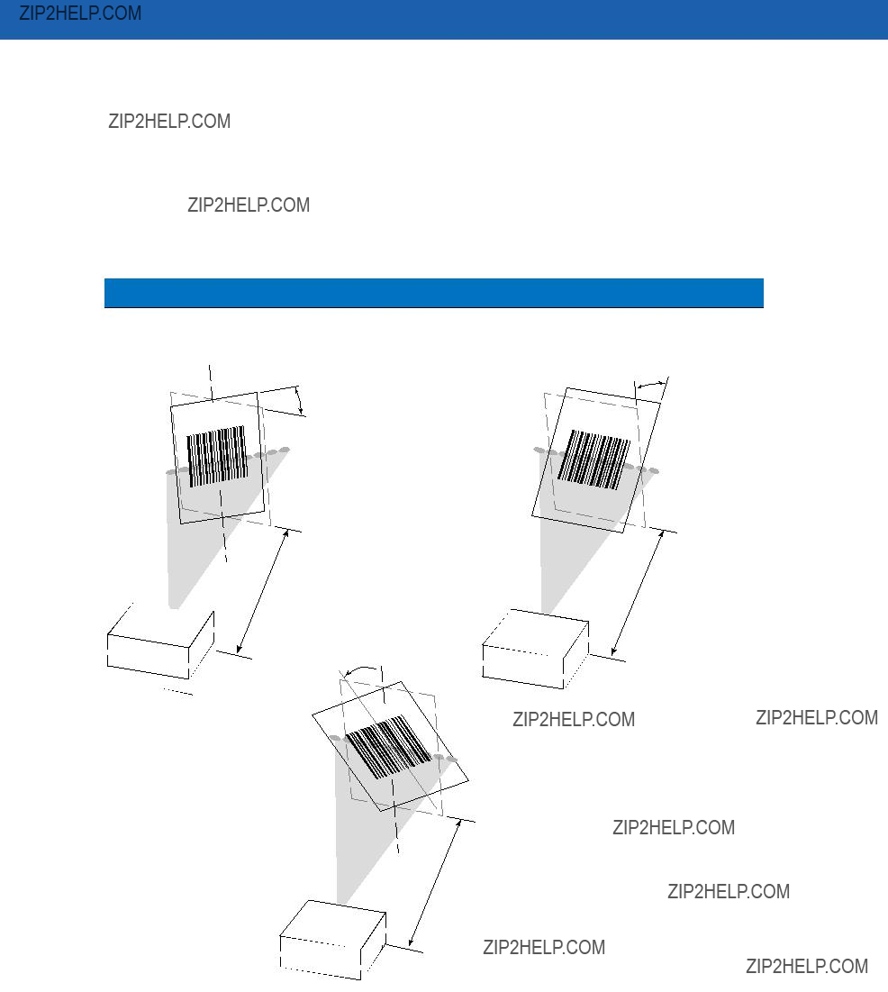
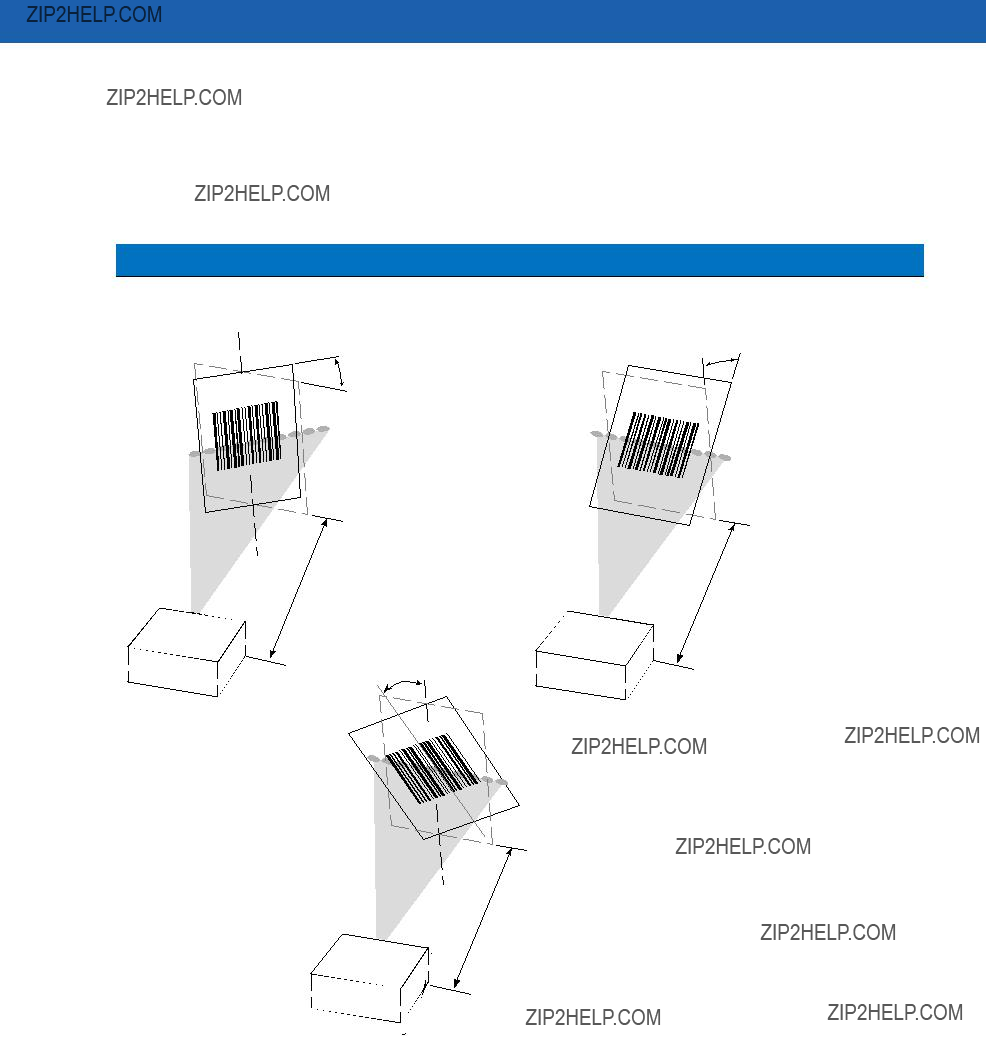
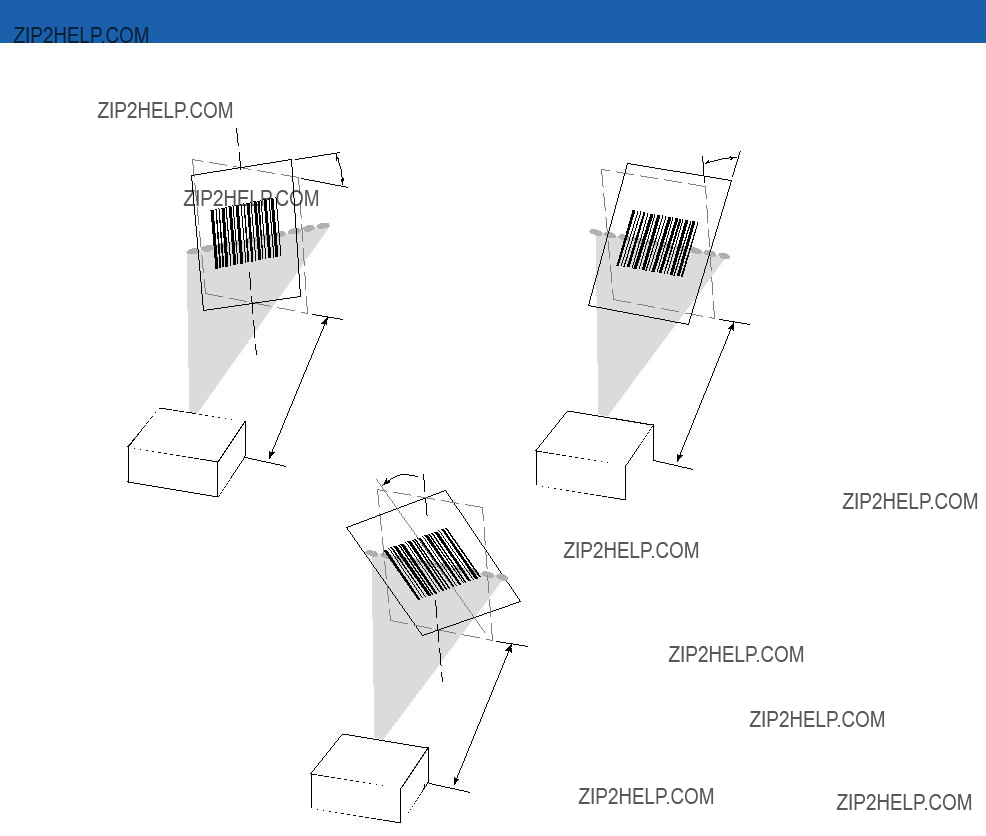
5.Position the symbol so that the scan line is as near as possible to perpendicular to the bars and spaces in the symbol.
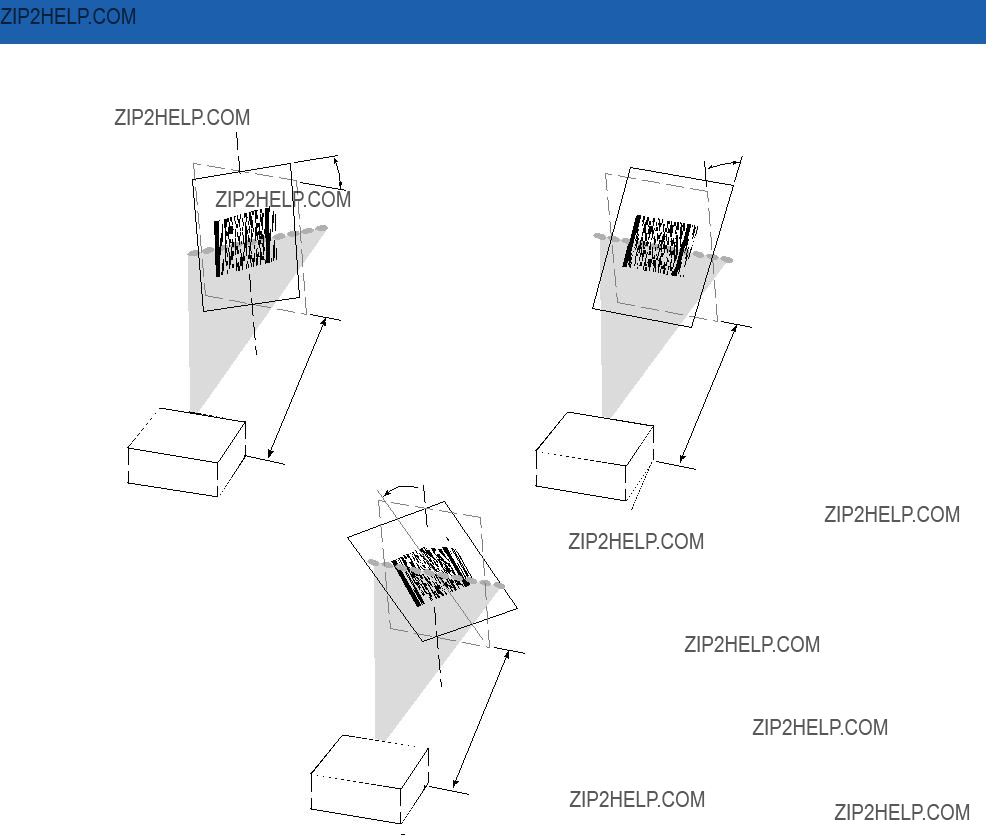
6.Avoid specular reflection (glare) off the symbol by tilting the top or bottom of the symbol away from the scanner. The exact angle is not critical, but it must be large enough so that if a mirror were inserted in the symbol location, the reflected scan line would miss the front surface of the scanner. For the maximum allowable angles refer to the Skew, Pitch and Roll angles listed in each MiniScan Technical Specifications table.
7.If placing an additional window between the scanner and the symbol, determine the optimum symbol location using a representative window in the desired window position.
8.Give the scanner time to dwell on the symbol for several scans. When first enabled, the MiniScan may take two or three scans before it reaches maximum performance. Enable the MiniScan before presenting the symbol, if possible.
2 - 10 Symbol MiniScan MSXX07 Series Integration Guide
Conveyor Applications
Conveyor applications require setting the conveyor velocity to optimize the scanner???s ability to read symbols. Also consider the orientation of the symbol with respect to the conveyor direction. Figure
Symbol is Perpendicular to Conveyor Movement
With the symbol bars perpendicular to the conveyor belt direction (Picket Fence presentation) the relationship is:
V = (R x
where:
V = Velocity of the conveyor (inches/second)
R = Scan Rate (see technical specifications)
F = 80% of width of scan beam
W = Symbol Width (inches)
N = Number of scans over symbol (minimum of 10 scans)
F=Field Width
W=Symbol Width
Direction of Conveyor
Scan Beam
Perpendicular to Symbol
Figure
Example
R = 640 scans per second F = 80% of 6 in.
W = 4 in. N = 10
V = (640 x ((0.8 x 6) - 4))) / 10 = 51.2 in./sec

Installation 2 - 11
Symbol is Parallel to Conveyor Movement
With the symbol bars parallel to the conveyor belt direction (ladder presentation) the relationship is:
V = (R x H) / N
where:
V = Velocity of the conveyor (inches/second)
R = Scan Rate of scanner (see technical specifications)
H = Symbol height
N = Number of scans over symbol (minimum of 10 scans)
Scan Beam
Figure
Example
Use the previous formula to calculate the number of scans for a specific bar code, scanner, and conveyor speed; a minimum of 10 scans per symbol is recommended.
R = 640 scans/sec
H = 60 mil
N = 10 scans
V = (640 x .060) / 10 = 3.84 in./sec
2 - 12 Symbol MiniScan MSXX07 Series Integration Guide
Embedded Applications Requiring a Window
Use the following guidelines for applications that require a window in front of the MiniScan.
NOTE Motorola does not recommend placing an exit window in front of the MiniScan; however, the following information is provided for applications that require such a window.
Window Material
Many window materials that look perfectly clear can contain stresses and distortions that can reduce scanner performance. For this reason, Motorola highly recommends only optical glass or
CAUTION Consult an
NOTE Do not use polycarbonate material.
Acrylic
When fabricated by
Chemically Tempered Float Glass
Glass is a hard material which provides excellent scratch and abrasion resistance. However, unannealed glass is brittle. Increasing flexibility strength with minimal optical distortion requires chemical tempering. Glass cannot be ultrasonically welded and is difficult to cut into odd shapes.

Installation 2 - 13
Table
Window Coatings
Table
Apply an
Polysiloxane Coating
Polysiloxane type coatings are applied to plastic surfaces to improve the surface resistance to both scratch and abrasion. They are usually applied by dipping, then

2 - 14 Symbol MiniScan MSXX07 Series Integration Guide
Table
Embedded Window Angle and Position
If a window is placed between the MiniScan and the item to scan, observe the following guidelines:
???Window Clear Opening - Make the clear opening of the window large enough so that the entire scan beam passes through the window. Cutting off any part of the beam can result in internal reflections and degrade decode range performance. Ensure that window placement relative to the MiniScan accounts for tolerances on all parts involved in that assembly.
???Window Angle - Angle the window at least 2o more than the tilt of the window on the scanner (see Table
???Optical Working Range - Adding a window can reduce the working range of the scanner since there is a signal loss when passing through window material. To minimize this reduction, use a special coating described in Window Coatings on page

Installation 2 - 15
Table
Accessories
The following accessories are available for the MiniScan scanner, and can be found in Symbol???s Solution Builder (ordering guide).
???For power connection
???110V power supply kit, US, p/n
???220V power supply, Europe, p/n
???100V power supply, Asia, p/n
???264V Universal power supply (also order cables below), p/n
???DC line cord (power supply to scanner), p/n
???AC line cord (wall outlet to power supply), p/n
???
???TTL
???Female DB9 with straight connector to
???Female DB9 with straight connector to
???Female DB9 with straight connector to
???Female DB9 with right angle connector to
???Female DB9 with straight connector to
???USB
???Female DB9 with straight connector with trigger jack and beeper to USB (Type A connector), p/n
???Female DB9 with right angle connector to USB host (Type A connector), p/n
???Female DB9 straight to USB, p/n
???Synapse Adapter
???Female DB9 with straight connector to Synapse Adapter Cable (6 ft. straight), p/n

2 - 16 Symbol MiniScan MSXX07 Series Integration Guide
???Cable Adapters
???Female 25 pin D, TxD on pin 2, p/n
???Female 25 pin D, TxD on pin 3, p/n
???Male 25 pin D, TxD on pin 2, p/n
???Male 25 pin D, TxD on pin 3, p/n
???Optional Accessories
???Push button trigger cable, p/n
???Photo sensor trigger cable, p/n
???
???Mounting bracket, p/n
Application Notes
TTL
Standard
USB Warning - Potential Host Side Issues
The Universal Serial Bus provides a smart
Typical symptoms of these environments are:
???Frequent scanner resets
???Scanner occasionally loses power (due to host initiated shutdown)
???Occasional host lockups.
Because

Chapter 3 Scanning
Introduction
This chapter provides information on scan patterns, scanning, triggering options, and beeper and LED definitions.
MiniScan Scan Patterns
Symbol MS1207FZY and MS1207WA Scan Pattern
Symbol MS1207FZY and MS1207WA scanners emit a single scan line to quickly decode 1D bar codes.
Figure

3 - 2 Symbol MiniScan MSXX07 Series Integration Guide
Symbol MS2207 and MS2207VHD Scan Patterns
The Symbol MS2207 and MS2207VHD generate different scan patterns (Smart Raster and High Density Single Scan Line) based on the software command received at the interface. Use the raster pattern to read 1D bar codes and PDF417 symbols.
NOTE The Symbol MS2207 and MS2207VHD also support omnidirectional and
Smart Raster Scan Pattern
The Symbol MS2207 and MS2207VHD can create a single line which opens vertically to read PDF417 symbols using the Smart Raster feature. This feature autodetects the type of bar code being scanned and adjusts its pattern accordingly, providing optimal performance on 1D, PDF417, GS1 DataBar, and Composite codes.
Stage 1: ???Slab??? Raster Pattern
Stage 2: Open Raster Pattern
Figure
High Density Single Scan Line Scan Pattern
The High Density single scan line appears as a "mini" raster and scans multiple areas of 1D codes to swiftly and accurately capture data on poorly printed and damaged bar codes.
Figure
Scanning 3 - 3
Symbol MS3207 Scan Patterns
The Symbol MS3207 generates four scan patterns based on the software command received at the interface. These patterns are Smart Raster,
Smart Raster Scan Pattern
The Symbol MS3207 can create a single line which opens vertically to read PDF417 symbols using the Smart Raster feature. This feature autodetects the type of bar code being scanned and adjusts its pattern accordingly, providing optimal performance on 1D, PDF417, GS1 DataBar, and Composite codes.
Stage 1: ???Slab??? Raster Pattern
Stage 2: Open Raster Pattern
Figure
The
Figure
3 - 4 Symbol MiniScan MSXX07 Series Integration Guide
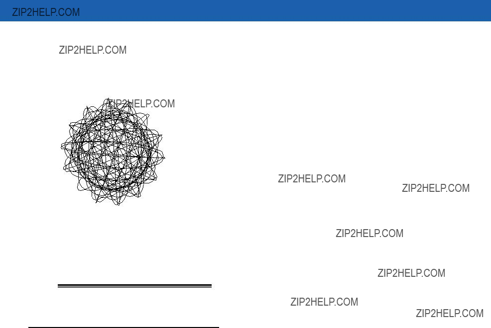
Omnidirectional Scan Pattern
The
Figure
High Density Single Scan Line Scan Pattern
The High Density single scan line appears as a "mini" raster and scans multiple areas of 1D codes to swiftly and accurately capture data on poorly printed and damaged bar codes.
Figure
Scan Angle Selection
The Symbol MS1207FZY scanner supports two scan angles (see Table
Operation in Blink Mode
The scan angle during Blink Mode is determined by the scan angle system parameter.
Scanning 3 - 5
Scanning Tips
When scanning, make sure the symbol is within the scanning range. See Calculating the Usable Scan Length Method on page
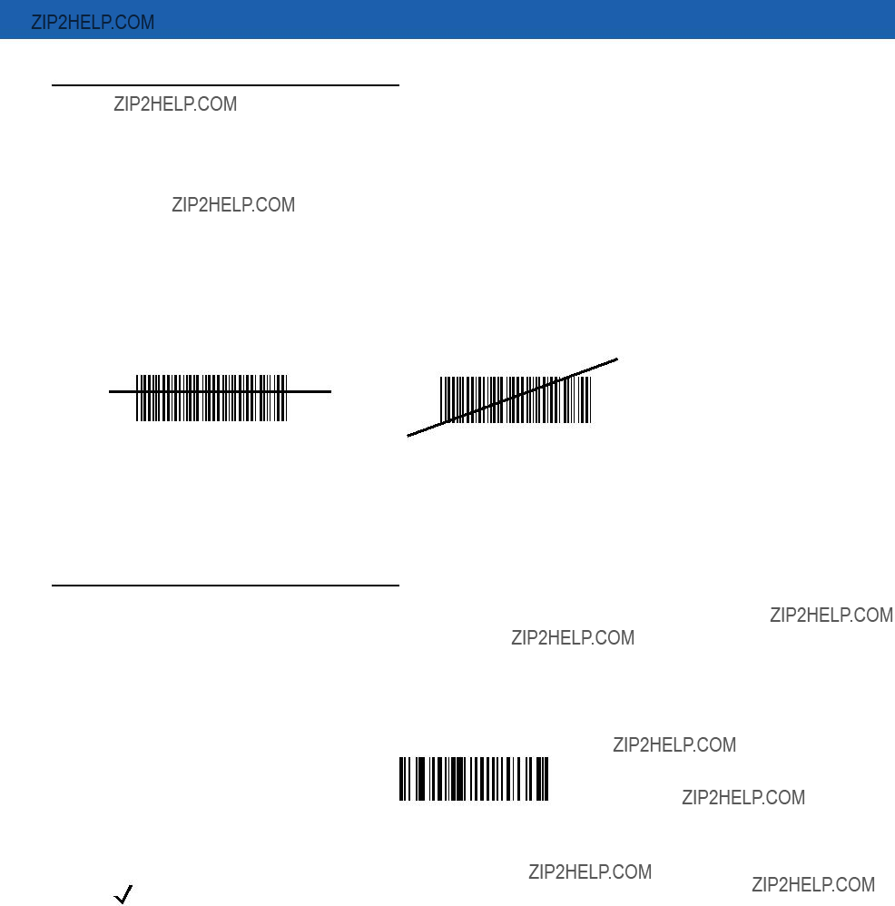
Scan the Entire Symbol
???The scan beam must cross every bar and space on the symbol.
???The larger the symbol, the farther away the scanner should be positioned.
???Position the scanner closer for symbols with bars that are close together.
Position at an Angle
Do not position the scanner exactly perpendicular to the bar code. In this position, light can bounce back into the scanner's exit window and prevent a successful decode.
Trigger Options
Continuous (Default)
The laser is enabled continuously and decode processing is continuously active. You can configure the scanner to scan and transmit a bar code, and then not decode the same bar code or any bar code for a set period of time. See Timeout Between Decodes on page
Continuous
NOTE This option is not recommended during scanner programming via bar code menus.
3 - 6 Symbol MiniScan MSXX07 Series Integration Guide
Level Trigger
Activating the trigger line enables the laser and begins decode processing. Decode processing continues until a good decode occurs, the trigger is released, or the Laser On Time expires. The laser is disabled once decode processing completes. The next decode attempt does not occur until the trigger line is released and then reactivated.
Level
Pulse Trigger
Activating the trigger line enables the laser and begins decode processing. Decode processing continues regardless of the trigger line until a good decode occurs, or until the Laser On Time expires. The laser is disabled once decode processing completes. The next decode attempt does not occur until the trigger line is released and then reactivated.
Pulse
Blink
NOTE Only the Symbol MS1207FZY and MS1207WA support this option.
The laser blinks at a 25% duty cycle (reduced to 10% after 30 seconds of inactivity), until a bar code is presented. When a bar code is presented, the laser remains on until either the bar code is decoded or removed, or the session timeout expires. Once the bar code is decoded, the scanner does not decode it again until the bar code is removed.
Blink

Scanning 3 - 7

3 - 8 Symbol MiniScan MSXX07 Series Integration Guide

Chapter 4 Symbol MS1207FZY Specifications
Introduction
This chapter provides the technical specifications for the Symbol MS1207FZY scanner.
4 - 2 Symbol MiniScan MSXX07 Series Integration Guide
Symbol MS1207FZY Specifications 4 - 3
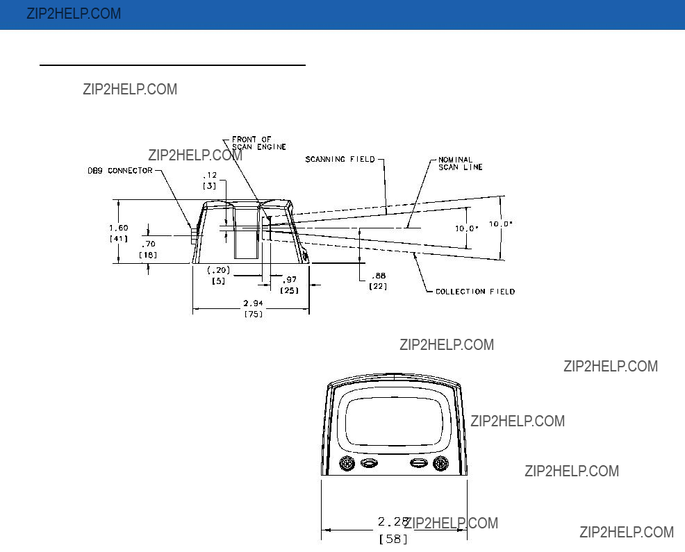
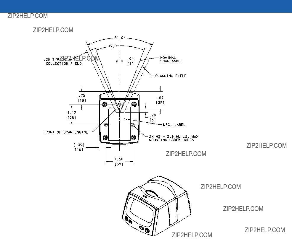
Symbol MS1207FZY Mechanical Drawings
Notes:
Unless otherwise specified:
???Dimensions are in inches, dimensions in [ ] are mm.
???User mounting tolerances are not included.
Figure
4 - 4 Symbol MiniScan MSXX07 Series Integration Guide
Notes:
Unless otherwise specified:
???Dimensions are in inches, dimensions in [ ] are mm.
???User mounting tolerances are not included.
Figure
Symbol MS1207FZY Specifications 4 - 5
4 - 6 Symbol MiniScan MSXX07 Series Integration Guide
Table
Note: Environmental and/or tolerance parameters are not cumulative.
SkewPitch
+ 50?? from normal
Skew
Angle
20mil Symbol
20 mil Symbol
Roll
Roll + 20?? from normal
Angle
20mil Symbol
Note: Tolerances are reduced at extreme ends of the working range.
Scan Beam
Figure

Symbol MS1207FZY Specifications 4 - 7
Symbol MS1207FZY Decode Zone
The scanner has a selectable scan angle of either 30?? or 42??. Figure
Note: Typical performance at 68??F (20??C) on high quality symbols.
5mil
3.25
 7.00
7.00
 66.75
66.75
 75.00
75.00
Depth of Field
*Minimum distance determined by symbol length and scan angle
Figure
4 - 8 Symbol MiniScan MSXX07 Series Integration Guide
Table
Notes:
1. Contrast measured as Mean Reflective Difference (MRD) at 650 nm.
2. Near ranges on lower densities largely depend on the width of the bar code and the scan angle. 3. Working range specifications: Photographic quality symbols, pitch = 10??, skew = 0??, roll = 0??, ambient light < 150 ft. candles, and temperature = 23 ??C.
Usable Scan Length
The decode zone is a function of various symbol characteristics including density, print contrast,
Calculating the Usable Scan Length Method on page

Chapter 5 Symbol MS1207WA Specifications
Introduction
This chapter provides the technical specifications for the Symbol MS1207WA scanner.

5 - 2 Symbol MiniScan MSXX07 Series Integration Guide
Symbol MS1207WA Specifications 5 - 3
Symbol MS1207WA Mechanical Drawings
Notes:
Unless otherwise specified:
???Dimensions are in inches, dimensions in [ ] are mm.
???User mounting tolerances are not included.
Figure

5 - 4 Symbol MiniScan MSXX07 Series Integration Guide
Notes:
Unless otherwise specified:
???Dimensions are in inches, dimensions in [ ] are mm.
???User mounting tolerances are not included.
Figure

Symbol MS1207WA Specifications 5 - 5
5 - 6 Symbol MiniScan MSXX07 Series Integration Guide
Table
Note: Environmental and/or tolerance parameters are not cumulative.
SkewPitch
+ 65?? from normal
Skew
Angle
20mil Symbol
Scan Beam
Roll
20 mil Symbol
Scan Beam
Roll
+ 20?? from normal
Angle
20mil Symbol
Note: Tolerances are reduced at extreme ends of the working range.
Scan Beam
Figure
Symbol MS1207WA Specifications 5 - 7
Symbol MS1207WA Decode Zone
Figure
Note: Typical performance at 73.4??F (23??C) on high quality symbols.
In. cm
12.431.6
W i d
6 15.2 t
h
f
F
6 15.2 i
e l d
12.431.6
Depth of Field
*Minimum distance determined by symbol length and scan angle
Figure

5 - 8 Symbol MiniScan MSXX07 Series Integration Guide
Table
1. Contrast measured as Mean Reflective Difference (MRD) at 670 nm.
2. Near ranges on lower densities (not specified) largely depend on the width of the bar code and the scan angle.
3. Working range specifications at ambient temperature 23 ??C.
Usable Scan Length
The decode zone is a function of various symbol characteristics including density, print contrast,
Calculating the Usable Scan Length Method on page

Chapter 6 Symbol MS2207 Specifications
Introduction
This chapter provides the technical specifications for the Symbol MS2207 scanner.
6 - 2 Symbol MiniScan MSXX07 Series Integration Guide
Symbol MS2207 Specifications 6 - 3
Symbol MS2207 Mechanical Drawings
Notes:
Unless otherwise specified:
???Dimensions are in inches, dimensions in [ ] are mm.
???User mounting tolerances are not included.
Figure
6 - 4 Symbol MiniScan MSXX07 Series Integration Guide
Notes:
Unless otherwise specified:
???Dimensions are in inches, dimensions in [ ] are mm.
???User mounting tolerances are not included.
Figure

Symbol MS2207 Specifications 6 - 5

6 - 6 Symbol MiniScan MSXX07 Series Integration Guide
Table
Symbol MS2207 Specifications 6 - 7
Skew
+ 49?? from normal
Skew
Angle
15mil Symbol
Scan Beam
Pitch
+ 55?? from normal Pitch??? Angle
15 mil Symbol
Scan Beam
Roll
+ 20?? from normal
Roll
Angle
15mil Symbol 


Note: Tolerances are reduced at extreme ends of the working range.
Scan Beam
Figure
6 - 8 Symbol MiniScan MSXX07 Series Integration Guide
Symbol MS2207 Decode Zones
The decode zone is a function of various symbol characteristics including density, print contrast, wide to narrow ratio and edge acurity. Typical values appear. Table
Symbol MS2207 1D Decode Zone
Note: Typical performance at 68??F (20??C)
on high quality symbols in normal room light. Vcc = 5V
MS 220X
6 mil
2.0
 5.25
5.25
7.5mil
1.5
 7.0
7.0
13 mil Minimum Element Width

 14.0
14.0
20 mil Minimum Element Width

 19.0
19.0
40 mil Minimum Element Width
* 
 24.0
24.0
55 mil Minimum Element Width
 31.0
31.0
2.55.1
2.55.1
Depth of Field
* Minimum distance determined by symbol length and scan angle.
Figure
Symbol MS2207 Specifications 6 - 9
Symbol MS2207 1D Decode Distances
Table
Notes:
1. Contrast measured as Mean Reflective Difference (MRD) at 650 nm.
2. Near ranges on lower densities largely depend on the width of the bar code and the scan angle.
3. Working range specifications: Photographic quality symbols, pitch = 10??, skew = 0??, roll = 0??, ambient light < 150 ft. candles, and temperature = 23 ??C.
6 - 10 Symbol MiniScan MSXX07 Series Integration Guide
Symbol MS2207 2D Decode Zone
Note: Typical performance at 68??F (20??C) on high quality symbols in normal room light.
W
Vcc = 5V
In. cm
i
5 12.7
2.5 6.35
2.5 6.35
6.6mil
1.5
 6.0
6.0
10 mil Minimum Element Width, 80%
3.5 
 9.0
9.0
15 mil Minimum Element Width
5.6 
 15.0
15.0
Depth of Field
Figure
d t h
o f
F i e l d
NOTE Not optimized for omnidirectional mode.
Symbol MS2207 Specifications 6 - 11
Symbol MS2207 2D Decode Distances
Table
1.Contrast measured as Mean Reflective Difference (MRD) at 650 nm.
2.Near ranges on lower densities largely depend on the width of the bar code and the scan angle.
3.Working range specifications: Photographic quality symbols, pitch = 10??, skew = 0??, roll = 0??, ambient light < 150 ft. candles, and temperature = 23 ??C.
NOTE Not optimized for omnidirectional mode.
Usable Scan Length
The decode zone is a function of various symbol characteristics including density, print contrast,
Calculating the Usable Scan Length Method on page

6 - 12 Symbol MiniScan MSXX07 Series Integration Guide

Chapter 7 Symbol MS2207VHD
Specifications
Introduction
This chapter provides the technical specifications for the Symbol MS2207VHD scanner.
7 - 2 Symbol MiniScan MSXX07 Series Integration Guide
Symbol MS2207VHD Specifications 7 - 3
Symbol MS2207VHD Mechanical Drawings
Notes:
Unless otherwise specified:
???Dimensions are in inches, dimensions in [ ] are mm.
???User mounting tolerances are not included.
Figure
7 - 4 Symbol MiniScan MSXX07 Series Integration Guide
Notes:
Unless otherwise specified:
???Dimensions are in inches, dimensions in [ ] are mm.
???User mounting tolerances are not included.
Figure

Symbol MS2207VHD Specifications 7 - 5

7 - 6 Symbol MiniScan MSXX07 Series Integration Guide
Table
Symbol MS2207VHD Specifications 7 - 7
Skew
+ 15?? from normal
Skew
Angle
10mil Symbol
Scan Beam
Pitch
10 mil Symbol
Scan Beam
Roll
10mil Symbol 


Note: Tolerances are reduced at extreme ends of the working range.
Scan Beam
Figure
7 - 8 Symbol MiniScan MSXX07 Series Integration Guide
Symbol MS2207VHD Decode Zones
The decode zone is a function of various symbol characteristics including density, print contrast, wide to narrow ratio and edge acurity. Typical values appear. Table
Symbol MS2207VHD 1D Decode Zone
Note: Typical performance at 68??F (20??C)
on high quality symbols in normal room light. Vcc = 5V
MS 220XVHD
4mil
2.0
 3.4
3.4
7.5mil
1.5
 5.25
5.25
Depth of Field
* Minimum distance determined by symbol length and scan angle.
Figure
2.55.1
2.55.1

Symbol MS2207VHD Specifications 7 - 9
Symbol MS2207VHD 1D Decode Distances
Table
Notes:
1. Contrast measured as Mean Reflective Difference (MRD) at 650 nm.
2. Near ranges on lower densities largely depend on the width of the bar code and the scan angle. 3. Working range specifications: Photographic quality symbols, pitch = 10??, skew = 0??,, roll = 0??,
ambient light < 150 ft. candles, and temperature = 23 ??C.
7 - 10 Symbol MiniScan MSXX07 Series Integration Guide
Symbol MS2207VHD 2D Decode Zone
Note: Typical performance at 68??F (20??C) on high quality symbols
in normal room light.
MS 220XVHD
4.0 mil
1.90
 3.00
3.00
6.6 mil
1.50 
 4.75
4.75
10 mil, 35% MRD
3.00
 5.75
5.75
Depth of Field
Figure
NOTE Not optimized for omnidirectional mode.
Symbol MS2207VHD Specifications 7 - 11
Symbol MS2207VHD 2D Decode Distances
Table
Notes:
1. Contrast measured as Mean Reflective Difference (MRD) at 650 nm.
2. Near ranges on lower densities largely depend on the width of the bar code and the scan angle. 3. Working range specifications: Photographic quality symbols, pitch = 10??, skew = 0??,
roll = 0??, ambient light < 150 ft. candles, and temperature = 23 ??C.
NOTE Not optimized for omnidirectional mode.
Usable Scan Length
The decode zone is a function of various symbol characteristics including density, print contrast,
Calculating the Usable Scan Length Method on page

7 - 12 Symbol MiniScan MSXX07 Series Integration Guide

Chapter 8 Symbol MS3207 Specifications
Introduction
This chapter provides the technical specifications for the Symbol MS3207 scanner.
8 - 2 Symbol MiniScan MSXX07 Series Integration Guide
Symbol MS3207 Electrical Interface
This section describes the pin functions of the Symbol MS3207 interface.
*I = Input O = Output

Symbol MS3207 Specifications 8 - 3
Table

8 - 4 Symbol MiniScan MSXX07 Series Integration Guide
Symbol MS3207 Mechanical Drawings
Notes:
Unless otherwise specified:
???Dimensions are in inches, dimensions in [ ] are mm.
???User mounting tolerances are not included.
Figure
Symbol MS3207 Specifications 8 - 5
Notes:
Unless otherwise specified:
???Dimensions are in inches, dimensions in [ ] are mm.
???User mounting tolerances are not included.
Figure

8 - 6 Symbol MiniScan MSXX07 Series Integration Guide
Symbol MS3207 Technical Specifications
Table

Symbol MS3207 Specifications 8 - 7
Table
8 - 8 Symbol MiniScan MSXX07 Series Integration Guide
Skew
+ 15?? from normal
Skew
Angle
20mil Symbol
Scan Beam
Pitch
20 mil Symbol
Scan Beam
Roll
Roll +4?? from normal
Angle
20mil Symbol
Note: Tolerances are reduced at extreme ends of the working range.
Scan Beam
Figure
Symbol MS3207 Specifications 8 - 9
Symbol MS3207 Decode Zones
The decode zone is a function of various symbol characteristics including density, print contrast, wide to narrow ratio and edge acuity. Typical values appear. Table
Symbol MS3207 Omnidirectional Decode Distances
Note: Typical performance at 68??F (20??C)
on high quality symbols in normal room light. Vcc = 5V
6 mil
.25 
 3.25
3.25
80% UPC
1.00 
1.5 
1.75
 6.5
6.5
100% UPC
 12.5
12.5
20 mil
 12.5
12.5
Depth of Field
Depth of Field
* Minimum distance determined by symbol length and scan angle.
Figure
8 - 10 Symbol MiniScan MSXX07 Series Integration Guide
Table
Notes:
1. Contrast measured as Mean Reflective Difference (MRD) at 650 nm.
2. Near ranges on largely depend on the width of the bar code and the scan angle.
3. Working range specifications: Photographic quality symbols, pitch = 15??, skew = 0??, roll = 0??, ambient light < 150 ft. candles, and temperature = 23 ??C, Vcc = 5V.
4. Measured from the front of the scanner.
Symbol MS3207 Specifications 8 - 11
Symbol MS3207 2D Slab/Raster Decode Distances
Note: Typical performance at 68??F (20??C)
on high quality symbols in normal room light. Vcc = 5V
6.6mil PDF 417
1.0
 5.25
5.25
55 mil 1D
1.0
In. cm
11 27.9
10 25.4
7.515.2
5 10.1
2.55.1
0 0
2.55.1
5 10.1
7.515.2
10 25.4
11 27.9
32.0
W i d t h
o f
F i e l d
Depth of Field
* Minimum distance determined by symbol length and scan angle.
Figure
8 - 12 Symbol MiniScan MSXX07 Series Integration Guide
Table
Notes:
1. Contrast measured as Mean Reflective Difference (MRD) at 650 nm.
2. Near ranges on largely depend on the width of the bar code and the scan angle.
3. Working range specifications: Photographic quality symbols, pitch = 15??, skew = 0??, roll = 0??, ambient light < 150 ft. candles, and temperature = 23 ??C, Vcc = 5V.
4. Measured from the front of the scanner.
Usable Scan Length
The decode zone is a function of various symbol characteristics including density, print contrast,
Calculating the Usable Scan Length Method on page

Chapter 9 Maintenance and Troubleshooting
Introduction
The chapter provides information on maintenance and troubleshooting.
Maintenance
Cleaning the exit window is the only maintenance required. Do not allow any abrasive material to touch the window. Clean the scan window with a damp cloth and, if necessary, a

9 - 2 Symbol MiniScan MSXX07 Series Integration Guide
Troubleshooting
Table
NOTE If after performing these checks the symbol still does not scan, contact the distributor or Motorola Enterprise Mobility Support. See page xv for contact information.
Chapter 10 Parameter Menus
Introduction
This chapter describes the programmable parameters, and provides bar codes for programming. Throughout the programming bar code menus, asterisks (*) indicate default values.
Operational Parameters
MiniScan scanners ship with the default settings in Table
To change the default values, scan the appropriate bar codes in this chapter. These new values replace the standard default values in memory. To reset the default parameter values, scan the Set All Defaults bar code on page

10 - 2 Symbol MiniScan MSXX07 Series Integration Guide

Parameter Menus 10 - 3
Table

10 - 4 Symbol MiniScan MSXX07 Series Integration Guide
Table

Parameter Menus 10 - 5
Table

10 - 6 Symbol MiniScan MSXX07 Series Integration Guide
Table

Parameter Menus 10 - 7
10 - 8 Symbol MiniScan MSXX07 Series Integration Guide
Scanning Options
Beeper Volume
To select a decode beep volume, scan the Low Volume, Medium Volume, or High Volume bar code.
Low Volume
Medium Volume
*High Volume
Parameter Menus 10 - 9
Beeper Tone
To select a decode beep frequency (tone), scan the appropriate bar code.
Low Frequency
Medium Frequency
*High Frequency
Beeper Frequency Adjustment
This parameter adjusts the frequency of the high beeper tone from the nominal 2500 Hz to another frequency matching the resonances of the installation. Program this in 10 Hz increments from 1220 Hz to 3770 Hz.
To increase the frequency, scan the bar code below, then scan three numeric bar codes beginning on page
To decrease the frequency, scan the bar code below, then scan three numeric bar codes beginning on page
Beeper Frequency Adjustment
(Default: 2500 Hz)
10 - 10 Symbol MiniScan MSXX07 Series Integration Guide
Laser On Time
This parameter sets the maximum time decode processing continues during a scan attempt. It is programmable in 0.1 second increments from 0.5 to 9.9 seconds.
To set a Laser On Time, scan the bar code below. Next scan two numeric bar codes beginning on page
Laser On Time
Scan Angle
NOTE This option is supported by the Symbol MS1207FZY only.
This parameter sets the scan angle to the default or alternate angle.
*Default Angle
Alternate Angle
Parameter Menus 10 - 11
Power Mode
This parameter determines whether or not power remains on after a decode attempt. In Low Power mode, the scanner enters into a low power consumption mode when possible, provided all WAKEUP signals are released. In Continuous On mode, power remains on after each decode attempt.
Continuous On
*Low Power
Trigger Mode
???Level - A trigger pull activates the laser and decode processing. The laser remains on and decode processing continues until a trigger release, a valid decode, or the Laser On
???Pulse - A trigger pull activates the laser and decode processing. The laser remains on and decode processing continues until a valid decode or the Laser On
???Continuous - The laser is always on and decoding.
???Blink - This trigger mode is used for triggerless ScanStand operation. Scanning range is reduced in this mode. This mode is only supported by Symbol MS1207FZY models.
10 - 12 Symbol MiniScan MSXX07 Series Integration Guide
Scanning Mode
NOTE These options are supported by the Symbol MS2207, MS2207VHD, and MS3207 only.
Select one of the following scanning modes:
NOTE If you select Omnidirectional, Motorola recommends disabling the following parameters: PDF417, MicroPDF417, DataBar Limited,
Parameter Menus 10 - 13
Aiming Mode
For handheld mode only, select an aiming dot to appear for a normal or extended period of time.
*No Aiming Dot
Aiming Dot
Normal (200 ms) Timeout
Aiming Dot
Extended (400 ms) Timeout
10 - 14 Symbol MiniScan MSXX07 Series Integration Guide
Programmable Raster Height and Raster Expansion Speed
NOTE Only the Symbol MS2207, MS2207VHD, and MS3207 support these options.
If you enabled Programmable Raster or Always Raster, this parameter selects the laser pattern???s height and rate of expansion. This parameter is intended for very specific applications, and is usually not necessary.
To select the laser pattern???s height and/or rate of expansion:
1.Scan the bar code for either Raster Height or Raster Expansion Speed below.
2.Scan two numeric bar codes beginning on page
To change the selection or to cancel an incorrect entry, scan the Cancel bar code on page
Raster Height (Default 15)
Raster Expansion Speed (Default 11)
Parameter Menus 10 - 15
Timeout Between Decodes
Timeout Between Decodes, Same Symbol
When in Continuous triggering mode, this parameter sets the minimum duration of not decoding data before the scanner decodes a second bar code identical to one just decoded. This reduces the risk of accidentally scanning the same symbol twice. It is programmable in 0.1 second increments from 0.0 to 9.9 seconds. The recommended interval is 0.6 seconds
Timeout Between Decodes, Different Symbol
This option sets the minimum duration of not decoding data before the scanner decodes a second (different) bar code. Use this in Continuous mode to prevent the scanner from decoding when a different symbol appears in the scanner's field of view before the timeout period between decodes expires. This is programmable in 0.1 second increments from 0.0 to 9.9 seconds. The recommended value is 0.0 seconds.
Select the timeout between decodes for the same or different symbols.
1.Scan the option bar code to set.
2.Scan two numeric bar codes beginning on page
To change the selection or to cancel an incorrect entry, scan the Cancel bar code on page
Timeout Between Decodes -
Same Symbol
Timeout Between Decodes -
Different Symbols

10 - 16 Symbol MiniScan MSXX07 Series Integration Guide
Beep After Good Decode
Scan this symbol to set the scanner to beep after a good decode.
*Beep After Good Decode
Scan this symbol to set the scanner not to beep after a good decode. The beeper still operates during parameter menu scanning and indicates error conditions.
Do Not Beep After Good Decode
Transmit ???No Read??? Message
Enable this option to transmit ???NR??? if a
Enable No Read
If you disable this parameter, and a symbol can not be decoded, no message is sent to the host.
*Disable No Read

Parameter Menus 10 - 17
Parameter Scanning
To disable the decoding of parameter bar codes, scan the bar code below. The scanner can still decode the Set Defaults parameter bar code. To enable decoding of parameter bar codes, either scan *Enable Parameter Scanning or Set All Defaults.
*Enable Parameter Scanning
Disable Parameter Scanning
10 - 18 Symbol MiniScan MSXX07 Series Integration Guide
Linear Code Type Security Level
NOTE Does not apply to Code 128.
MiniScan scanners offer four levels of decode security for linear code types (e.g., Code 39, Interleaved 2 of 5). Select higher security levels for decreasing levels of bar code quality. As security levels increase, the scanner???s aggressiveness decreases.
Select the security level appropriate for bar code quality.
Linear Security Level 1
The following code types must be successfully read twice before being decoded:
Linear Security Level 1
Linear Security Level 2
All code types must be successfully read twice before being decoded.
*Linear Security Level 2
Parameter Menus 10 - 19
Linear Security Level 3
Code types other than the following must be successfully read twice before being decoded. The following codes must be read three times:
Linear Security Level 3
Linear Security Level 4
All code types must be successfully read three times before being decoded.
Linear Security Level 4
This parameter is only valid if you enabled a Linear Code Type Security Level on page
Enable
*Disable
10 - 20 Symbol MiniScan MSXX07 Series Integration Guide
UPC/EAN
Enable/Disable
To enable or disable
*Enable
Disable
Enable/Disable
To enable or disable
*Enable
Disable
Parameter Menus 10 - 21
Enable/Disable
To enable or disable
Enable
*Disable
Enable/Disable
To enable or disable
*Enable
Disable

10 - 22 Symbol MiniScan MSXX07 Series Integration Guide
Enable/Disable
To enable or disable
*Enable
Disable
Enable/Disable Bookland EAN
To enable or disable EAN Bookland, scan the appropriate bar code below.
Enable Bookland EAN
*Disable Bookland EAN
NOTE If you enable Bookland EAN, select a Bookland ISBN Format on page
Parameter Menus 10 - 23
UPC/EAN Coupon Code
Enable this to decode
Enable UPC/EAN
Coupon Code
*Disable UPC/EAN
Coupon Code
NOTE Use the Decode UPC/EAN Supplemental Redundancy on page
10 - 24 Symbol MiniScan MSXX07 Series Integration Guide
Decode UPC/EAN Supplementals
Supplementals are bar codes appended according to specific format conventions (e.g., UPC A+2, UPC E+2, EAN 13+2). The following options are available:
???If you select Ignore UPC/EAN with Supplementals, and the scanner is presented with a UPC/EAN plus supplemental symbol, the scanner decodes UPC/EAN and ignores the supplemental characters.
???If you select Decode UPC/EAN with Supplementals, the scanner only decodes UPC/EAN symbols with supplemental characters, and ignores symbols without supplementals.
???If you select Autodiscriminate UPC/EAN Supplementals, the scanner decodes UPC/EAN symbols with supplemental characters immediately. If the symbol does not have a supplemental, the scanner must decode the bar code the number of times set via Decode UPC/EAN Supplemental Redundancy on page
???If you select one of the following Supplemental Mode options, the scanner immediately transmits
???Enable 378/379 Supplemental Mode
???Enable 978/979 Supplemental Mode
NOTE If you select 978/979 Supplemental Mode and are scanning Bookland EAN bar codes, see Enable/Disable Bookland EAN on page
Bookland ISBN Format on page
???Enable 977 Supplemental Mode
???Enable 414/419/434/439 Supplemental Mode
???Enable 491 Supplemental Mode
???Enable Smart Supplemental Mode - applies to
???Supplemental
???Supplemental
???Smart Supplemental Plus
???Smart Supplemental Plus
NOTE To minimize the risk of invalid data transmission, select either to decode or ignore supplemental characters.
Parameter Menus 10 - 25
Decode UPC/EAN Supplementals (continued)
Select the desired option by scanning one of the following bar codes.
Decode UPC/EAN With Supplementals
*Ignore UPC/EAN Supplementals
Autodiscriminate UPC/EAN Supplementals
Enable 378/379 Supplemental Mode
Enable 978/979 Supplemental Mode
10 - 26 Symbol MiniScan MSXX07 Series Integration Guide
Decode UPC/EAN Supplementals (continued)
Enable 977 Supplemental Mode
Enable 414/419/434/439 Supplemental Mode
Enable 491 Supplemental Mode
Enable Smart Supplemental Mode
Parameter Menus 10 - 27
Decode UPC/EAN Supplementals (continued)
Supplemental
Supplemental
Smart Supplemental Plus
Smart Supplemental Plus
10 - 28 Symbol MiniScan MSXX07 Series Integration Guide
If you selected a Supplemental
Decode UPC/EAN Supplemental Redundancy
With Autodiscriminate UPC/EAN Supplementals selected, this option adjusts the number of times (from 2 to 30) to decode a symbol without supplementals before transmission. Motorola recommends five or above when decoding a mix of UPC/EAN symbols with and without supplementals.
Scan the bar code below to select a decode redundancy value. Next scan two numeric bar codes beginning on page
Decode UPC/EAN
Supplemental Redundancy
Parameter Menus 10 - 29
Transmit
Scan the appropriate bar code below to transmit the symbol with or without the
*Transmit
Do Not Transmit
Transmit
Scan the appropriate bar code below to transmit the symbol with or without the
*Transmit
Do Not Transmit

10 - 30 Symbol MiniScan MSXX07 Series Integration Guide
Transmit
Scan the appropriate bar code below to transmit the symbol with or without the
*Transmit
Do Not Transmit
Parameter Menus 10 - 31
Select one of the following options to transmit a
No Preamble
(<DATA>)
*System Character
(<SYSTEM CHARACTER> <DATA>)
System Character & Country Code
(< COUNTRY CODE> <SYSTEM CHARACTER> <DATA>)
10 - 32 Symbol MiniScan MSXX07 Series Integration Guide
Select one of the following options to transmit a
No Preamble
(<DATA>)
*System Character
(<SYSTEM CHARACTER> <DATA>)
System Character & Country Code
(< COUNTRY CODE> <SYSTEM CHARACTER> <DATA>)
Parameter Menus 10 - 33
Select one of the following options to transmit a
No Preamble
(<DATA>)
*System Character
(<SYSTEM CHARACTER> <DATA>)
System Character & Country Code
(< COUNTRY CODE> <SYSTEM CHARACTER> <DATA>)
10 - 34 Symbol MiniScan MSXX07 Series Integration Guide
Convert
This parameter converts
Scan Do Not Convert
Convert
(Enable)
*Do Not Convert
(Disable)
Convert
Enable this parameter to convert
Scan Do Not Convert
Convert
(Enable)
*Do Not Convert
(Disable)
Parameter Menus 10 - 35
EAN Zero Extend
Enable this to add five leading zeros to decoded
Disable this parameter to transmit
Enable EAN Zero Extend
*Disable EAN Zero Extend

10 - 36 Symbol MiniScan MSXX07 Series Integration Guide
Bookland ISBN Format
If you enabled Bookland EAN using Enable/Disable Bookland EAN on page
???Bookland
???Bookland
*Bookland
Bookland
NOTE For Bookland EAN to function properly, first enable Bookland EAN using Enable/Disable Bookland EAN on page
Parameter Menus 10 - 37
UPC/EAN Security Level
MiniScan scanners offer four levels of decode security for UPC/EAN bar codes. Select higher levels of security for decreasing levels of bar code quality. Increasing security decreases the scanner???s aggressiveness, so choose only that level of security necessary for the application.
UPC/EAN Security Level 0
This default setting allows the scanner to operate in its most aggressive state, while providing sufficient security in decoding
*UPC/EAN Security Level 0
UPC/EAN Security Level 1
Select this option if misdecodes occur. This security level eliminates most misdecodes.
UPC/EAN Security Level 1
UPC/EAN Security Level 2
Select this option if Security level 1 fails to eliminate misdecodes.
UPC/EAN Security Level 2
UPC/EAN Security Level 3
If misdecodes still occur after selecting Security Level 2, select this security level. Be advised, selecting this option is an extreme measure against misdecoding severely out of spec bar codes. Selecting this level of security significantly impairs the scanner???s decoding ability. If you need this level of security, try to improve the quality of the bar codes.
UPC/EAN Security Level 3

10 - 38 Symbol MiniScan MSXX07 Series Integration Guide
Linear UPC/EAN Decode
This option applies to code types containing two adjacent blocks (e.g.,
Enable Linear UPC/EAN Decode
*Disable Linear UPC/EAN Decode
UPC Half Block Stitching
NOTE Only the Symbol MS2207, MS2207VHD and MS3207 support this option.
This parameter enables UPC Half Block Stitching.
Enable UPC Half Block Stitching
*Disable UPC Half Block Stitching
Parameter Menus 10 - 39
Code 128
Enable/Disable Code 128
To enable or disable Code 128, scan the appropriate bar code below.
*Enable Code 128
Disable Code 128
Enable/Disable
To enable or disable
*Enable
Disable

10 - 40 Symbol MiniScan MSXX07 Series Integration Guide
Enable/Disable ISBT 128
To enable or disable ISBT 128, scan the appropriate bar code below.
Enable ISBT 128
*Disable ISBT 128
Lengths for Code 128
No length setting is required for Code 128.
Parameter Menus 10 - 41
Code 128 Decode Performance
NOTE Only the Symbol MS2207, MS2207VHD and MS3207 support this option.
This option offers three levels of decode performance or ???aggressiveness??? for Code 128 symbols. Increasing the performance level reduces the amount of required bar code orientation, useful when scanning very long and/or truncated bar codes. Increased levels reduce decode security.
If you enable this option, you can select a Decode Performance level from the next page to suit performance needs.
*Enable Code 128 Decode Performance
Disable Code 128 Decode Performance
10 - 42 Symbol MiniScan MSXX07 Series Integration Guide
Code 128 Decode Performance Level
NOTE Only the Symbol MS2207, MS2207VHD and MS3207 support this option.
Select a level of decode performance.
Code 128 Decode Performance Level 1
Code 128 Decode Performance Level 2
*Code 128 Decode Performance Level 3
Parameter Menus 10 - 43
Code 39
Enable/Disable Code 39
To enable or disable Code 39, scan the appropriate bar code below.
*Enable Code 39
Disable Code 39
Enable/Disable Trioptic Code 39
Trioptic Code 39 is a variant of Code 39 used in marking computer tape cartridges. Trioptic Code 39 symbols always contain six characters. Do not enable Trioptic Code 39 and Code 39 Full ASCII simultaneously.
To enable or disable Trioptic Code 39, scan the appropriate bar code below.
Enable Trioptic Code 39
*Disable Trioptic Code 39
10 - 44 Symbol MiniScan MSXX07 Series Integration Guide
Convert Code 39 to Code 32
Code 32 is a variant of Code 39 used by the Italian pharmaceutical industry. Scan the appropriate bar code to enable or disable converting Code 39 to Code 32.
NOTE Code 39 must be enabled for this parameter to function.
Convert Code 39 To Code 32
*Do Not Convert Code 39 To Code 32
Code 32 Prefix
Enable this parameter to add the prefix character ???A??? to all Code 32 bar codes. Convert Code 39 to Code 32 must be enabled for this parameter to function.
*Enable Code 32 Prefix
Disable Code 32 Prefix
Parameter Menus 10 - 45
Set Lengths for Code 39
The length of a code refers to the number of characters (i.e., human readable characters), including check digit(s) the code contains. Set lengths for Code 39 to any length, one or two discrete lengths, or lengths within a specific range. If Code 39 Full ASCII is enabled, Length Within a Range or Any Length are the preferred options.
One Discrete Length - This option limits decodes to only Code 39 symbols containing a selected length. Select lengths using the Numeric Bar Codes on page
Code 39 - One Discrete Length
Two Discrete Lengths - This option limits decodes to only those Code 39 symbols containing either of two selected lengths. Select lengths using the Numeric Bar Codes on page
Code 39 - Two Discrete Lengths
Length Within Range - This option limits decodes to only those Code 39 symbols within a specified range. Select lengths using the Numeric Bar Codes on page
*Code 39 - Length Within Range
Any Length - Scan this option to decode Code 39 symbols containing any number of characters.
Code 39 - Any Length
10 - 46 Symbol MiniScan MSXX07 Series Integration Guide
Code 39 Check Digit Verification
Enable this feature to check the integrity of all Code 39 symbols to verify that the data complies with specified check digit algorithm. The scanner only decodes Code 39 symbols which include a modulo 43 check digit.
Enable Code 39 Check Digit
*Disable Code 39 Check Digit
Transmit Code 39 Check Digit
Scan this symbol to transmit the check digit with the data.
Transmit Code 39 Check Digit
(Enable)
Scan this symbol to transmit data without the check digit.
*Do Not Transmit Code 39 Check Digit
(Disable)
Parameter Menus 10 - 47
Enable/Disable Code 39 Full ASCII
To enable or disable Code 39 Full ASCII, scan the appropriate bar code below.
When enabled, the ASCII character set assigns a code to letters, punctuation marks, numerals, and most control keystrokes on the keyboard.
The first 32 codes are
Code 39 Full ASCII interprets the bar code special character ($ + % /) preceding a Code 39 character and assigns an ASCII character value to the pair. For example, when Code 39 Full ASCII is enabled and a +B is scanned, it is interpreted as b, %J as ?, and $H emulates the keystroke BACKSPACE. Scanning ABC$M outputs the keystroke equivalent of ABC ENTER.
Do not enable Code 39 Full ASCII and Trioptic Code 39 simultaneously.
The scanner does not autodiscriminate between Code 39 and Code 39 Full ASCII.
Enable Code 39 Full ASCII
*Disable Code 39 Full ASCII
10 - 48 Symbol MiniScan MSXX07 Series Integration Guide
Code 39 Decode Performance
NOTE Only the Symbol MS2207, MS2207VHD, and MS3207 support this option.
This option offers three levels of decode performance or ???aggressiveness??? for Code 39 symbols. Increasing the performance level reduces the amount of required bar code orientation, useful when scanning very long and/or truncated bar codes. Increased levels reduce decode security.
If you enable this option, you can select a Decode Performance level from the next page to suit performance needs.
NOTE This option only works with Code 39 One Discrete Length.
*Enable Code 39 Decode Performance
Disable Code 39 Decode Performance
Parameter Menus 10 - 49
Code 39 Decode Performance Level
NOTE Only the Symbol MS2207, MS2207VHD, and MS3207 support this option.
Select a level of decode performance.
Code 39 Decode Performance Level 1
Code 39 Decode Performance Level 2
*Code 39 Decode Performance Level 3

10 - 50 Symbol MiniScan MSXX07 Series Integration Guide
Code 93
Enable/Disable Code 93
To enable or disable Code 93, scan the appropriate bar code below.
Enable Code 93
*Disable Code 93
Parameter Menus 10 - 51
Set Lengths for Code 93
The length of a code refers to the number of characters (i.e., human readable characters), including check digit(s) the code contains. Select lengths for Code 93 for any length, one or two discrete lengths, or lengths within a specific range.
One Discrete Length - Select this option to decode only codes containing a selected length. Select lengths using the Numeric Bar Codes on page
Code 93 - One Discrete Length
Two Discrete Lengths - Select this option to decode only codes containing two selected lengths. Select lengths using the Numeric Bar Codes on page
Code 93 - Two Discrete Lengths
Length Within Range - Select this option to decode only those codes within a specified range. Select lengths using the Numeric Bar Codes on page
*Code 93 - Length Within Range
Any Length - Scan this option to decode Code 93 symbols containing any number of characters.
Code 93 - Any Length
10 - 52 Symbol MiniScan MSXX07 Series Integration Guide
Code 11
Enable/Disable Code 11
To enable or disable Code 11, scan the appropriate bar code below.
Enable Code 11
*Disable Code 11
Parameter Menus 10 - 53
Set Lengths for Code 11
The length of a code refers to the number of characters (i.e., human readable characters), including check digit(s) the code contains. Set lengths for Code 11 to any length, one or two discrete lengths, or lengths within a specific range.
One Discrete Length - Select this option to decode only codes containing a selected length. Select lengths using the Numeric Bar Codes on page
Code 11 - One Discrete Length
Two Discrete Lengths - Select this option to decode only codes containing two selected lengths. Select lengths using the Numeric Bar Codes on page
Code 11 - Two Discrete Lengths
Length Within Range - Select this option to decode only codes within a specified range. Select lengths using the Numeric Bar Codes on page
*Code 11 - Length Within Range
Any Length - Scan this option to decode Code 11 symbols containing any number of characters.
Code 11 - Any Length
10 - 54 Symbol MiniScan MSXX07 Series Integration Guide
Code 11 Check Digit Verification
Enable this to check the integrity of a Code 11 symbol to ensure it complies with a specified check digit algorithm. Select either to check for one check digit, check for two check digits, or to disable the feature.
*Disable
One Check Digit
Two Check Digits
Parameter Menus 10 - 55
Transmit Code 11 Check Digit
Scan this symbol to transmit the check digit with the data.
Transmit Code 11 Check Digit
(Enable)
Scan this symbol to transmit data without the check digit.
*Do Not Transmit Code 11 Check Digit
(Disable)
10 - 56 Symbol MiniScan MSXX07 Series Integration Guide
Interleaved 2 of 5
Enable/Disable Interleaved 2 of 5
To enable or disable Interleaved 2 of 5, scan the appropriate bar code below.
Enable Interleaved 2 of 5
*Disable Interleaved 2 of 5
Parameter Menus 10 - 57
Set Lengths for Interleaved 2 of 5
The length of a code refers to the number of characters (i.e., human readable characters) the code contains, and includes check digits. Set lengths for I 2 of 5 to any length, one or two discrete lengths, or lengths within a specific range.
One Discrete Length - Select this option to decode only codes containing a selected length. Select lengths using the Numeric Bar Codes on page
*I 2 of 5 - One Discrete Length
Two Discrete Lengths - Select this option to decode only codes containing two selected lengths. Select lengths using the Numeric Bar Codes on page
I 2 of 5 - Two Discrete Lengths
Length Within Range - Select this option to decode only codes within a specified range. Select lengths using the Numeric Bar Codes on page
I 2 of 5 - Length Within Range
Any Length - Scan this option to decode I 2 of 5 symbols containing any number of characters.
NOTE Selecting this option can lead to misdecodes for I 2 of 5 codes.
I 2 of 5 - Any Length
10 - 58 Symbol MiniScan MSXX07 Series Integration Guide
I 2 of 5 Check Digit Verification
Enable this to check the integrity of an I 2 of 5 symbol to ensure it complies with a specified algorithm, either USS (Uniform Symbology Specification), or OPCC (Optical Product Code Council).
*Disable
USS Check Digit
OPCC Check Digit
Parameter Menus 10 - 59
Transmit I 2 of 5 Check Digit
Scan this symbol to transmit the check digit with the data.
Transmit I 2 of 5 Check Digit
(Enable)
Scan this symbol to transmit data without the check digit.
*Do Not Transmit I 2 of 5 Check Digit
(Disable)
Convert I 2 of 5 to
This parameter converts a 14 character I 2 of 5 code into
Convert I 2 of 5 to
*Do Not Convert I 2 of 5 to
10 - 60 Symbol MiniScan MSXX07 Series Integration Guide
Discrete 2 of 5
Enable/Disable Discrete 2 of 5
To enable or disable Discrete 2 of 5, scan the appropriate bar code below.
Enable Discrete 2 of 5
*Disable Discrete 2 of 5
Parameter Menus 10 - 61
Set Lengths for Discrete 2 of 5
The length of a code refers to the number of characters (i.e., human readable characters) the code contains, and includes check digits. Set lengths for D 2 of 5 to any length, one or two discrete lengths, or lengths within a specific range.
One Discrete Length - Select this option to decode only codes containing a selected length. Select lengths using the Numeric Bar Codes on page
*D 2 of 5 - One Discrete Length
Two Discrete Lengths - Select this option to decode only codes containing two selected lengths. Select lengths using the Numeric Bar Codes on page
D 2 of 5 - Two Discrete Lengths
Length Within Range - Select this option to decode codes within a specified range. Select lengths using the Numeric Bar Codes on page
D 2 of 5 - Length Within Range
Any Length - Scan this option to decode D 2 of 5 symbols containing any number of characters.
NOTE Selecting this option can lead to misdecodes for D 2 of 5 codes.
D 2 of 5 - Any Length

10 - 62 Symbol MiniScan MSXX07 Series Integration Guide
Codabar
Enable/Disable Codabar
To enable or disable Codabar, scan the appropriate bar code below.
Enable Codabar
*Disable Codabar
Parameter Menus 10 - 63
Set Lengths for Codabar
The length of a code refers to the number of characters (i.e., human readable characters) the code contains, including start or stop characters. Set lengths for Codabar to any length, one or two discrete lengths, or lengths within a specific range.
One Discrete Length - Select this option to decode only codes containing a selected length. Select lengths using the Numeric Bar Codes on page
Codabar - One Discrete Length
Two Discrete Lengths - Select this option to decode only codes containing two selected lengths. Select lengths using the Numeric Bar Codes on page
Codabar - Two Discrete Lengths
Length Within Range - Select this option to decode a code within a specified range. Select lengths using the Numeric Bar Codes on page
*Codabar - Length Within Range
Any Length - Scan this option to decode Codabar symbols containing any number of characters.
Codabar - Any Length
10 - 64 Symbol MiniScan MSXX07 Series Integration Guide
CLSI Editing
Enable this to strip the start and stop characters and insert a space after the first, fifth, and tenth characters of a
NOTE Symbol length does not include start and stop characters.
Enable CLSI Editing
*Disable CLSI Editing
NOTIS Editing
Enable this to strip the start and stop characters from decoded Codabar symbol.
Enable NOTIS Editing
*Disable NOTIS Editing
Parameter Menus 10 - 65
MSI Plessey
Enable/Disable MSI Plessey
To enable or disable MSI Plessey, scan the appropriate bar code below.
Enable MSI Plessey
*Disable MSI Plessey
10 - 66 Symbol MiniScan MSXX07 Series Integration Guide
Set Lengths for MSI Plessey
The length of a code refers to the number of characters (i.e., human readable characters) the code contains, and includes check digits. Set lengths for MSI Plessey to any length, one or two discrete lengths, or lengths within a specific range.
One Discrete Length - Select this option to decode only codes containing a selected length. Select lengths using the Numeric Bar Codes on page
MSI Plessey - One Discrete Length
Two Discrete Lengths - Select this option to decode only codes containing two selected lengths. Select lengths using the Numeric Bar Codes on page
MSI Plessey - Two Discrete Lengths
Length Within Range - Select this option to decode codes within a specified range. Select lengths using the Numeric Bar Codes on page
*MSI Plessey - Length Within Range
Any Length - Scan this option to decode MSI Plessey symbols containing any number of characters.
NOTE Selecting this option can cause misdecodes for MSI Plessey codes.
MSI Plessey - Any Length
Parameter Menus 10 - 67
MSI Plessey Check Digits
These check digits at the end of the bar code verify the integrity of the data. At least one check digit is required. Check digits are not automatically transmitted with the data.
*One MSI Plessey Check Digit
If you select two check digits, also select an MSI Plessey Check Digit Algorithm. See page
Two MSI Plessey Check Digits
Transmit MSI Plessey Check Digit
Scan this symbol to transmit the check digit with the data.
Transmit MSI Plessey Check Digit
(Enable)
Scan this symbol to transmit data without the check digit.
*Do Not Transmit MSI Plessey Check Digit
(Disable)

10 - 68 Symbol MiniScan MSXX07 Series Integration Guide
MSI Plessey Check Digit Algorithm
If you selected Two MSI Plessey Check Digits, an additional verification is required to ensure integrity. Select one of the following algorithms.
MOD 10/ MOD 11
*MOD 10/ MOD 10

Parameter Menus 10 - 69
PDF417/MicroPDF417
NOTE Only the Symbol MS2207, MS2207VHD, and MS3207 support these options.
Enable/Disable PDF417
To enable or disable PDF417, scan the appropriate bar code below.
Enable PDF417
Disable PDF417
Enable/Disable MicroPDF417
To enable or disable MicroPDF417, scan the appropriate bar code below.
Enable MicroPDF417
*Disable MicroPDF417
10 - 70 Symbol MiniScan MSXX07 Series Integration Guide
MicroPDF Performance
If you have problems decoding MicroPDF symbols, select Selective Performance.
This can decrease decoding aggressiveness on some symbols.
*Standard Performance for MicroPDF
Selective Performance for
MicroPDF
Parameter Menus 10 - 71
Code 128 Emulation
Enable this parameter to transmit data from certain MicroPDF417 symbols as Code 128. You must enable Transmit AIM Symbology Identifiers for this parameter to work.
Enabling Code 128 Emulation transmits these MicroPDF417 symbols with one of the following prefixes:
]C1 if the first codeword is
]C0 if the first codeword is 910 or 911
Disabling this transmits them with one of the following prefixes:
]L3 if the first codeword is
]L5 if the first codeword is 910 or 911
Scan a bar code below to enable or disable Code 128 Emulation.
Enable Code 128 Emulation
*Disable Code 128 Emulation
10 - 72 Symbol MiniScan MSXX07 Series Integration Guide
GS1 DataBar
GS1
To enable or disable GS1
Enable GS1
*Disable GS1
GS1 DataBar Limited
To enable or disable GS1 DataBar Limited, scan the appropriate bar code below.
Enable GS1 DataBar Limited
*Disable GS1 DataBar Limited
Parameter Menus 10 - 73
GS1 DataBar Expanded
To enable or disable GS1 DataBar Expanded, scan the appropriate bar code below.
Enable GS1 DataBar Expanded
*Disable GS1 DataBar Expanded
Convert GS1 DataBar to UPC/EAN
NOTE The Symbol MS1207FZY and MS1207WA only support this option.
This parameter only applies to GS1
Bar codes beginning with two or more zeros but not six zeros have the leading '0100' stripped and the bar code reported as
Enable Convert GS1 DataBar to UPC/EAN
*Disable Convert GS1 DataBar to UPC/EAN
10 - 74 Symbol MiniScan MSXX07 Series Integration Guide
Composite
NOTE Only the Symbol MS2207, MS2207VHD, and MS3207 support these options.
Composite
Scan a bar code below to enable or disable Composite bar codes of type
Enable
*Disable
Composite
Scan a bar code below to enable or disable Composite bar codes of type
Enable
*Disable

Parameter Menus 10 - 75
Composite
Scan a bar code below to enable or disable Composite bar codes of type
Enable TLC39
*Disable TLC39
10 - 76 Symbol MiniScan MSXX07 Series Integration Guide
UPC Composite Mode
UPC symbols can be ???linked??? with a 2D symbol during transmission as if they were one symbol. Three options are offered for these symbols:
???Select UPC Never Linked to transmit UPC bar codes regardless of whether a 2D symbol is detected.
???Select UPC Always Linked to transmit UPC bar codes and the 2D portion. If 2D is not present, the UPC bar code does not transmit.
???If Autodiscriminate UPC Composites is selected, the scanner determines if there is a 2D portion, then transmits the UPC, as well as the 2D portion if present.
UPC Never Linked
*UPC Always Linked
Autodiscriminate UPC Composites
Parameter Menus 10 - 77
Data Options
Transmit Code ID Character
A code ID character identifies the code type of a scanned bar code. This is useful when decoding more than one code type. The code ID character is inserted between the prefix character (if selected) and the decoded symbol.
Select no code ID character, a Symbol Code ID character, or an AIM Code ID character. The Symbol Code ID characters are listed below.
Table
*Note: UPC/EAN Composite transmits in two portions, each with a "T" prefix.
10 - 78 Symbol MiniScan MSXX07 Series Integration Guide
Transmit Code ID Character (continued)
Symbol Code ID Character
AIM Code ID Character
*None

Parameter Menus 10 - 79
Prefix/Suffix Values
You can append a prefix and/or one or two suffixes to scan data to use in data editing. To set a value for a prefix or suffix, scan a
To change the selection or cancel an incorrect entry, scan the Cancel bar code on page
NOTE In order to use Prefix/Suffix values, first set the Scan Data Transmission Format on page
Scan Prefix
Scan Suffix 1
Scan Suffix 2
Data Format Cancel
10 - 80 Symbol MiniScan MSXX07 Series Integration Guide
Scan Data Transmission Format
To change the Scan Data Transmission Format, scan the Scan Options bar code below, then select one of four options:
???Data As Is
???<DATA> <SUFFIX>
???<PREFIX> <DATA>
???<PREFIX> <DATA> <SUFFIX>
NOTE To set values for the prefix and/or suffix, see Prefix/Suffix Values on page
After making a selection, scan the Enter bar code on page
To add a carriage return/enter after each bar code scanned, scan the following bar codes in order:
1.<SCAN OPTIONS>
2.<DATA> <SUFFIX>
Scan Options
*Data As Is
Parameter Menus 10 - 81
Scan Data Transmission Format (continued)
<DATA> <SUFFIX>
<PREFIX> <DATA>
<PREFIX> <DATA> <SUFFIX>
Enter
Data Format Cancel

10 - 82 Symbol MiniScan MSXX07 Series Integration Guide
Event Reporting
The host can request the decoder to provide certain information (events) relative to the decoder???s behavior. Enable or disable the events listed in Table
Table

Parameter Menus 10 - 83
Decode Event
When enabled, the scanner sends a message to the host when it successfully decodes a bar code. When disabled, no message is sent.
Enable
*Disable
Boot Up Event
When enabled, the scanner sends a message to the host when power is applied. When disabled, no message is sent.
Enable
*Disable

10 - 84 Symbol MiniScan MSXX07 Series Integration Guide
Parameter Menus 10 - 85
Macro PDF Features
NOTE Only the Symbol MS2207, MS2207VHD, and MS3207 support these options.
Transmit Symbols in Codeword Format
Enable this to transmit each PDF symbol as directly decoded data codewords, whether or not that symbol is part of a macro PDF sequence. Note that data is output as codeword values, not as interpreted data.
???Codeword values??? is an ASCII representation of a number from 000 to 928 for each codeword, preceded by an escape character. This escape character is a backslash by default, but you can change this value. For example, the codeword value 005 is sent to the host in the form of \005 for GLIs, and \C005C for ECIs. This output format is based on the AIM USA Uniform Symbology Specification for PDF417 (1994).
All output codewords are exactly 4 characters for GLIs and 6 characters for ECIs. However, there can be
Because GLIs are indistinguishable from other codewords in the output data stream, the host must recognize them as GLIs and process their interpretations.
Note that when a macro PDF sequence is transmitted, the last character in the last block of data transmitted is always \922 (if selected). This indicates the end of that macro PDF transmission.
Scan the appropriate bar code to enable or disable this.
Enable Transmit In Codeword Format
*Disable Transmit In Codeword Format
10 - 86 Symbol MiniScan MSXX07 Series Integration Guide
Transmit Unknown Codewords
Select Transmit Unknown Codewords to use the output codeword format for transmitting any
Transmit Unknown Codewords
*Do Not Transmit Unknown Codewords
Escape Characters
This enables the backslash (\) character as an Escape character for systems that can process transmissions containing special data sequences. Scan a bar code below to either format special data (e.g., GLI escapes, MacroPDF417 Control Block optional fields) according to the GLI (Global Label Identifier) protocol or the ECI (Extended Channel Interpretation) protocol, or to disable this parameter.
ECI Protocol
GLI Protocol
*None
Parameter Menus 10 - 87
Delete Character Set ECIs
Select Delete Character Set ECIs to delete any escape sequences representing Character Set ECIs (also known as GLIs) from its buffer before transmission. In many receiving systems, Character Set ECIs can be removed without affecting the way data is displayed or processed.
Select Transmit Character Set ECIs to transmit data from PDF417 and MicroPDF417 bar codes containing Character Set ECIs, even when the ECI Protocol is disabled.
Scan a bar code to delete or transmit character set ECIs.
Delete Character Set ECIs
*Transmit Character Set ECIs
ECI Decoder
This parameter enables the scanner to interpret any Extended Channel Interpretations (ECIs) that are supported by the scanner firmware. This does not affect symbols not encoded using ECIs. This version of the product supports ECIs 000900 through 000913, used for efficient encoding of Common Data Syntax Format
Scan a bar code to enable or disable this option.
*Enable ECI Decoder
Disable ECI Decoder
10 - 88 Symbol MiniScan MSXX07 Series Integration Guide
Transmit Macro PDF
NOTE Only the Symbol MS2207, MS2207VHD, and MS3207 support these options.
Enable or disable each of the following parameters to indicate whether or not to transmit the specified field in subsequently scanned Macro PDF417 symbols. The options cannot be changed in the middle of a Macro PDF set entry. All
Transmit File Name
Parameter # B0h
Transmit File Name activates transmission of the file name field. The field character tag is \923\000. For example, the filename MANHOURS.WK1 is sent as: \923\000MANHOURS.WK1.
Enable File Name Transmit
*Disable File Name Transmit

Parameter Menus 10 - 89
Transmit Block Count
Transmit Block Count activates transmission of the block count field. The field character tag is \923\001. For example, the field may be: \923\0011856.
Enable Transmit Block Count
*Disable Transmit Block Count
Transmit Time Stamp
Transmit Time Stamp activates transmission of the time stamp field. The field character tag is \923\002. For example, the field may be: \923\0022123443243234.
Enable Transmit Time Stamp
*Disable Transmit Time Stamp
10 - 90 Symbol MiniScan MSXX07 Series Integration Guide
Transmit Sender
Transmit Sender activates transmission of the sender field. The field character tag is \923\003. For example, the field may be: \923\003Motorola Holtsville, NY.
Enable Sender Transmit
*Disable Sender Transmit
Transmit Addressee
Transmit Addressee activates transmission of the addressee field. The field character tag is \923\004. For example, the field may be: \923\004AIM USA.
Enable Addressee Transmit
*Disable Addressee Transmit
Parameter Menus 10 - 91
Transmit Checksum
Transmit Checksum activates transmission of the checksum field. The field character tag is \923\006. For example, the field may be: \923\00663823.
Enable Checksum Transmit
*Disable Checksum Transmit
Transmit File Size
Transmit File Size activates transmission of the file size field. The field character tag is \923\005. For example, the field may be: \923\005179234.
Enable File Size Transmit
*Disable File Size Transmit
10 - 92 Symbol MiniScan MSXX07 Series Integration Guide
Transmit Macro PDF Control Header
Transmit Macro PDF Control Header activates transmission of the control header, which contains the segment index and the file ID. For example, the field can be: \92800000\725\120\343. The five digits after the \928 are the segment index (or block index), and \725\120\343 is the file ID.
Enable Macro PDF Control Header Transmit
*Disable Macro PDF Control Header Transmit
Last Blocker Marker
Enable Last Block Marker marks the last block in the set by the codeword \922.
Enable Last Block Marker
*Disable Last Block Marker
Parameter Menus 10 - 93
Numeric Bar Codes
For parameters requiring specific numeric values, scan the appropriately numbered bar code(s).
0
1
2
3
4
10 - 94 Symbol MiniScan MSXX07 Series Integration Guide
Numeric Bar Codes (continued)
5
6
7
8
9

Parameter Menus 10 - 95
Cancel
To change a selection or cancel an incorrect entry, scan the bar code below.
Cancel

10 - 96 Symbol MiniScan MSXX07 Series Integration Guide
Chapter 11
Introduction
This chapter provides
If Table
This scanner uses TTL
NOTE Particularly noisy electrical environments may require a cable with an
Throughout the programming bar code menus, asterisks (*) indicate default values.
* Indicates Default 
 *Baud Rate 9600
 Feature/Option
11 - 2 Symbol MiniScan MSXX07 Series Integration Guide
Table
NOTE See Chapter 9, Maintenance and Troubleshooting for all user preferences, hosts, symbologies, and miscellaneous parameters.
Table
1User selection is required to configure this interface; this is the most common selection.

Various
Table
*In the Nixdorf Mode B, if CTS is low, scanning is disabled. When CTS is high, scanning is enabled. **If Nixdorf Mode B is scanned without the scanner connected to the proper host, the scanner may not be able to scan. If this happens, scan a different

11 - 4 Symbol MiniScan MSXX07 Series Integration Guide
Selecting the ICL, Fujitsu,
Table
To select an
NOTE You must select an interface as there is no default; Standard
Standard
ICL
11 - 6 Symbol MiniScan MSXX07 Series Integration Guide
Olivetti ORS4500
Omron
OPOS/JPOS
Fujitsu
Baud Rate
Baud rate is the number of bits of data transmitted per second. Set the scanner's baud rate to match the host???s baud rate setting, or data may not reach the host device or may reach it in distorted form.
Baud Rate 600
Baud Rate 1200
Baud Rate 2400
Baud Rate 4800
*Baud Rate 9600
Baud Rate 19,200
Baud Rate 38,400
11 - 8 Symbol MiniScan MSXX07 Series Integration Guide
Parity
A parity check bit is the most significant bit of each ASCII coded character. Select the parity type according to host device requirements.
Select Odd parity to set the parity bit value to 0 or 1, based on data, to ensure that an odd number of 1 bits are contained in the coded character.
Odd
Select Even parity to set the parity bit value to 0 or 1, based on data, to ensure that an even number of 1 bits are contained in the coded character.
Even
Select Mark parity and the parity bit is always 1.
Mark
Select Space parity and the parity bit is always 0.
Space
Select None when no parity bit is required.
*None
Stop Bit Select
The stop bit(s) at the end of each transmitted character marks the end of transmission of one character and prepares the receiving device for the next character in the serial data stream. Select the number of stop bits (one or two) the host device is programmed to accommodate.
*1 Stop Bit
2 Stop Bits
Data Bits
This parameter allows the scanner to interface with devices requiring a
11 - 10 Symbol MiniScan MSXX07 Series Integration Guide
Check Receive Errors
Select whether or not to check the parity, framing, and overrun of received characters. The parity value of received characters is verified against the parity parameter selected earlier.
*Check For Received Errors
Do Not Check For Received Errors
Hardware Handshaking
The data interface consists of an
Disable Standard RTS/CTS handshaking to transmit scan data as it becomes available. Select Standard RTS/CTS handshaking to transmit scan data according to the following sequence:
???The scanner reads the CTS line for activity. If CTS is asserted, the scanner waits up to the Host Serial Response
???When the CTS line is negated, the scanner asserts the RTS line and waits up to the Host Serial Response
???When data transmission is complete, the scanner negates RTS 10 msec after sending the last character.
???The host responds by negating CTS. The scanner checks for a negated CTS upon the next transmission of data.
During data transmission, the CTS line should be asserted. If CTS is deasserted for more than 50 ms between characters, the transmission is aborted, the scanner sounds a transmission error, and the data is discarded.
If this communications sequence fails, the scanner issues an error indication. In this case, the data is lost and must be rescanned.
If Hardware Handshaking and Software Handshaking are both enabled, Hardware Handshaking takes precedence.
NOTE The DTR signal is jumpered to the active state.

None
Scan the bar code below if to disable Hardware Handshaking.
*None
Standard RTS/CTS
Scan the bar code below to select Standard RTS/CTS Hardware Handshaking.
Standard RTS/CTS
RTS/CTS Option 1
When RTS/CTS Option 1 is selected, the scanner asserts RTS before transmitting and ignores the state of CTS. The scanner
RTS/CTS Option 1
RTS/CTS Option 2
When Option 2 is selected, RTS is always high or low
RTS/CTS Option 2
RTS/CTS Option 3
When Option 3 is selected, the scanner asserts RTS prior to any data transmission, regardless of the state of CTS. The scanner waits up to the Host Serial Response
RTS/CTS Option 3
11 - 12 Symbol MiniScan MSXX07 Series Integration Guide
Software Handshaking
This parameter offers control of the data transmission process in addition to, or instead of, that offered by hardware handshaking. There are five options.
If Software Handshaking and Hardware Handshaking are both enabled, Hardware Handshaking takes precedence.
None
When this option is selected, data is transmitted immediately.
*None
ACK/NAK
When this option is selected, after transmitting data, the scanner expects either an ACK or NAK response from the host. When the scanner receives a NAK, it
The scanner waits up to the programmable Host Serial Response
ACK/NAK
ENQ
When this option is selected, the scanner waits for an ENQ character from the host before transmitting data. If the scanner does not receive an ENQ within the Host Serial Response
ENQ
ACK/NAK with ENQ
This combines the two previous options.
ACK/NAK with ENQ
XON/XOFF
An XOFF character turns the scanner transmission off until the scanner receives an XON character. There are two situations for XON/XOFF:
???The scanner receives XOFF before has it data to send. When the scanner has data to send, it waits up to Host Serial Response
???The scanner receives XOFF during a transmission. Data transmission then stops after sending the current byte. When the scanner receives an XON character, it sends the rest of the data message. The scanner waits indefinitely for the XON.
XON/XOFF
11 - 14 Symbol MiniScan MSXX07 Series Integration Guide
Host Serial Response
This parameter specifies how long the scanner waits for an ACK, NAK, or CTS before determining that a transmission error occurred. This only applies if you enabled an ACK/NAK Software Handshaking mode or RTS/CTS Hardware Handshaking mode.
*Minimum: 2 Sec
Low: 2.5 Sec
Medium: 5 Sec
High: 7.5 Sec
Maximum: 9.9 Sec
RTS Line State
This parameter sets the idle state of the Serial Host RTS line. Scan a bar code below to select Low RTS or High RTS line state.
*Host: Low RTS
Host: High RTS
Beep on <BEL>
When this parameter is enabled, the scanner issues a beep when a <BEL> character is detected on the
Beep On <BEL> Character
(Enable)
*Do Not Beep On <BEL> Character
(Disable)
11 - 16 Symbol MiniScan MSXX07 Series Integration Guide
Intercharacter Delay
This parameter specifies the intercharacter delay inserted between character transmissions.
*Minimum: 0 msec
Low: 25 msec
Medium: 50 msec
High: 75 msec
Maximum: 99 msec
Nixdorf Beep/LED Options
When Nixdorf Mode B is selected, this indicates when the scanner beeps and turns on its LED after a decode.
*Normal Operation (Beep/LED immediately after decode)
Beep/LED After Transmission
Beep/LED After CTS Pulse
Ignore Unknown Characters
Unknown characters are characters the host does not recognize. Select Send Bar Codes with Unknown Characters to transmit all bar code data except for unknown characters. The scanner sounds no error beeps. Select Do Not Send Bar Codes With Unknown Characters to send bar code data up to the first unknown character. The scanner sounds four error beeps.
*Send Bar Code
With Unknown Characters
Do Not Send Bar Codes
With Unknown Characters

11 - 18 Symbol MiniScan MSXX07 Series Integration Guide

Chapter 12 USB Interface
Introduction
This chapter describes how to connect and configure the Symbol MSXX07 Series scanner with a USB host. The MiniScan attaches directly to a USB host, or a powered USB hub, which powers it. No additional power supply is required. See Connecting the Symbol MSXX07 via USB on page
Throughout the programming bar code menus, asterisks (*) indicate default values.
 *North American, Standard USB Keyboard
Connecting a USB Interface
The scanner connects with USB hosts including:
???Desktop PCs and Notebooks
???Apple??? iMac, G4, iBooks (North America only)
???IBM SurePOS terminals
???Sun, IBM, and other network computers that support more than one keyboard.
The following operating systems support the scanner through USB:
???Windows 98, 2000, ME, XP
???MacOS 8.5 and above
???IBM 4690 OS.
The scanner also interfaces with other USB hosts that support USB Human Interface Devices (HID). For more information on USB technology, hosts, and peripheral devices, visit www.symbol.com/usb.

12 - 2 Symbol MiniScan MSXX07 Series Integration Guide
USB Default Parameters
Table
NOTE See Chapter 9, Maintenance and Troubleshooting for all user preferences, hosts, symbologies, and miscellaneous default parameters.
Table
USB Interface 12 - 3
USB Host Parameters
USB Device Type
Select the desired USB device type.
NOTE When changing USB Device Types, the scanner automatically restarts and issues the standard startup beep sequences.
*HID Keyboard Emulation
IBM Table Top USB
IBM
12 - 4 Symbol MiniScan MSXX07 Series Integration Guide
USB Country Keyboard Types (Country Codes)
Scan the bar code corresponding to the keyboard type. This setting applies only to the USB HID Keyboard Emulation device.
*North American Standard USB Keyboard
German Windows
French Windows

USB Interface 12 - 5
USB Country Keyboard Types (continued)
French Canadian Windows 95/98
French Canadian Windows 2000/XP
Spanish Windows
Italian Windows
12 - 6 Symbol MiniScan MSXX07 Series Integration Guide
USB Country Keyboard Types (continued)
Swedish Windows
UK English Windows
Japanese Windows (ASCII)
USB Interface 12 - 7
USB Keystroke Delay
This parameter sets the delay, in milliseconds, between emulated keystrokes. Scan a bar code below to increase the delay when hosts require a slower transmission of data.
*No Delay
Medium Delay (20 msec)
Long Delay (40 msec)
12 - 8 Symbol MiniScan MSXX07 Series Integration Guide
USB CAPS Lock Override
This option applies only to the HID Keyboard Emulation device. When enabled, the case of the data is preserved regardless of the state of the caps lock key. This setting is always enabled for the Japanese, Windows (ASCII) keyboard type.
Override Caps Lock Key
(Enable)
*Do Not Override Caps Lock Key
(Disable)
USB Interface 12 - 9
USB Ignore Unknown Characters
This option applies only to the HID Keyboard Emulation device and IBM device. Unknown characters are characters the host does not recognize. Select Send Bar Codes With Unknown Characters to send all bar code data except for unknown characters. No error beeps sound. When Do Not Send Bar Codes With Unknown Characters is selected, bar codes containing at least one unknown character are not sent to the host, and an error beep sounds.
*Send Bar Codes With Unknown Characters
(Transmit)
Do Not Send Bar Codes with Unknown Characters (Disable)
Emulate Keypad
When enabled, all characters are sent as ASCII sequences over the numeric keypad. For example ASCII A is sent as ???ALT make??? 0 6 5 ???ALT Break???.
*Disable Keypad Emulation
Enable Keypad Emulation
12 - 10 Symbol MiniScan MSXX07 Series Integration Guide
USB Keyboard FN 1 Substitution
This option applies only to the USB HID Keyboard Emulation device. Enable this to replace any FN 1 characters in an EAN 128 bar code with a Key Category and value.
Enable
*Disable
Function Key Mapping
ASCII values under 32 are normally sent as a
*Disable Function Key Mapping
Enable Function Key Mapping
USB Interface 12 - 11
Simulated Caps Lock
Enable this to invert upper and lower case characters on the scanned bar code as if the Caps Lock state is enabled on the keyboard. This is done regardless of the current state of the keyboard???s Caps Lock state.
*Disable Simulated Caps Lock
Enable Simulated Caps Lock
Convert Case
Enable this to convert all bar code data to the selected case.
*No Case Conversion
Convert All to Upper Case
Convert All to Lower Case

12 - 12 Symbol MiniScan MSXX07 Series Integration Guide

Chapter 13 Advanced Data Formatting
Introduction
Advanced Data Formatting (ADF) is a means of customizing data before transmission to the host device. Scan data can be edited to suit particular requirements.
Implement ADF by scanning a related series of bar codes, which begin on page
Avoid using ADF formatting with bar codes containing more than 60 characters. To add a prefix or suffix value for such bar codes, use Add Prefix/Suffix setting. Using ADF with longer bar codes transmits the bar code in segments of length 252 or less (depending on the host selected), and applies the rule to each segment
Rules: Criteria Linked to Actions
ADF uses rules to customize data. These rules perform detailed actions when the data meets certain criteria. One rule may consist of single or multiple criteria applied to single or multiple actions.
For instance, a data formatting rule could be:
Criteria: When scan data is Code 39, length 12, and data at the start position is the string ???129???,
Actions: pad all sends with zeros to length 8, send all data up to X,
send a space.
If you scan a Code 39 bar code of 1299X1559828, the following transmits: 00001299<space>. If you scan a Code 39 bar code of 1299X15598, this rule is ignored because the bar code does not meet the length criteria.
The rule specifies the editing conditions and requirements before data transmission occurs.

13 - 2 Symbol MiniScan MSXX07 Series Integration Guide
Using ADF Bar Codes
When programming a rule, make sure the rule is logically correct. Plan ahead before scanning.
To program each data formatting rule:
???Start the Rule. Scan the Begin New Rule bar code on page
???Criteria. Scan the bar codes for all pertinent criteria. Criteria can include code type (e.g., Code 128), code length, or data that contains a specific character string (e.g., the digits ???129???). These options are described in
???Actions. Scan all actions related to, or affecting, these criteria. The actions of a rule specify how to format the data for transmission. These options are described in ADF Bar Code Menu Example on page
???Save the Rule. Scan the Save Rule bar code on page
???Erase criteria, actions, and entire rules by scanning the appropriate bar code on page
ADF Bar Code Menu Example
This section provides an example of how to enter ADF rules for scan data.
An auto parts distribution center wants to encode manufacturer ID, part number, and destination code into their own Code 128 bar codes. The distribution center also has products that carry UPC bar codes, placed there by the manufacturer. The Code 128 bar codes have the following format:
MMMMMPPPPPDD
The distribution center uses a PC with dedicated control characters for manufacturer ID <CTRL M>, part number <CTRL P>, and destination code <CTRL D>. At this center the UPC data is treated as manufacturer ID code.
The following rules must be entered:
When scanning data of code type Code 128, send the next 5 characters, send the manufacturer ID key <CTRL M>, send the next 5 characters, send the part number key <CTRL P>, send the next 2 characters, send the destination code key <CTRL D>.
When scanning data of code type UPC/EAN, send all data, send the manufacturer ID key <CTRL M>.
To enter these rules, see the following steps:

Advanced Data Formatting 13 - 3
Rule 1: The Code 128 Scanning Rule
Rule 2: The UPC Scanning Rule
To correct any errors made while entering this rule, scan the Quit Entering Rules bar code on page
Alternate Rule Sets
Group ADF rules into one of four alternate sets which you can turn on and off when needed. This is useful to format the same message in different ways. For example, a Code 128 bar code contains the following information:
Class (2 digits), Stock Number (8) digits, Price (5 digits)
The bar code might look like this:
245671243701500
where:
Class = 24
Stock Number = 56712437
Price = 01500
Ordinarily, data is sent as follows:
24 (class key)
56712437 (stock key)
01500 (enter key)
But, when there is a sale, send only the following:
24 (class key)
56712437 (stock key)

13 - 4 Symbol MiniScan MSXX07 Series Integration Guide
and the cashier keys the price manually.
To implement this, first enter an ADF rule that applies to the normal situation, such as:
Scan Rule Belongs to Set 1. When scanning a bar code of length 15, send the next 2 characters, send the class key, send the next 8 characters, send the stock key, send the data that remains, send the Enter key.
The ???sale??? rule may look like this:
Scan Rule Belongs to Set 2. When scanning a bar code of length 15, send the next 2 characters, send the class key, send the next 8 characters, send the stock key.
To switch between the two sets of rules, program a ???switching rule??? to specify the type of bar code that must be scanned to switch between the rule sets. For example, in the case of the ???sale??? rule above, the rule programmer wants the cashier to scan the bar code ???M??? before a sale. To do this, enter the following rule:
When scanning a bar code of length 1 that begins with ???M???, select rule set number 1.
Program another rule to switch back.
When scanning a bar code of length 1 that begins with ???N???, turn off rule set number 1.
Or include the switching back to normal rules in the ???sale??? rule:
When scanning a bar code of length 15, send the next 2 characters, send the class key, send the next 8 characters, send the stock key, turn off rule set 1.
For optimal results, scan the Disable All Rule Sets bar code on page
In addition to enabling and disabling rule sets within the rules, enable or disable them by scanning the appropriate bar codes on page
Rules Hierarchy (in Bar Codes)
The order of programming individual rules is important.Program the most general rule first.
All programmed rules are stored in a buffer. As they are programmed, they are stored at the ???top??? of a rules list. If you created three rules, the list is configured as follows:
Third Rule
Second Rule
First Rule
When scanning data, the rules list is checked from top to bottom to determine if the criteria matches (and therefore, if the actions occur). Input is modified into the data format specified by the first matching set of criteria it finds. Be sure to program the most general rule first.
For example, if the THIRD rule states:
When scanning a bar code of any length, send all data, then send the ENTER key.
And the SECOND rule states:
When scanning a Code 128 bar code of length 12, send the first four characters, then send the ENTER key, then send all remaining data.
If you scan a Code 128 bar code of length 12, the THIRD rule would apply, and the SECOND rule would appear to not function.
Advanced Data Formatting 13 - 5
Note that the standard data editing functions also create ADF rules. Scan options are entered as ADF rules, and the hierarchy mentioned above also applies to them. For the scanner, this applies to prefix/suffix programming in the parameter Scan Data Transmission Format on page
These rules reside in the same ???rule list??? as ADF rules, so the order of their creation is also important.
Default Rules
Every unit has a default rule to send all scan data. Units with custom software may have one or more default rules burned in. The rules hierarchy checks user programmable rules first, then the default rules. To disable default rules enter the following general rule in the user programmable buffer:
When receiving scan data, send all data.
Since this rule always applies, ADF will never use the default rules.

13 - 6 Symbol MiniScan MSXX07 Series Integration Guide

Advanced Data Formatting 13 - 7
Table
13 - 8 Symbol MiniScan MSXX07 Series Integration Guide
Table
Special Commands
Pause Duration
This parameter, along with the Send Pause parameter on page
Pause Duration
Begin New Rule
Scan the bar code below to start entering a new rule.
Begin New Rule
Save Rule
Scan the bar code below to save the rule.
Save Rule
Advanced Data Formatting 13 - 9
Erase
Use these bar codes to erase criteria, actions, or rules.
Erase Criteria And Start Again
Erase Actions And Start Again
Erase Previously Saved Rule
Erase All Rules
Quit Entering Rules
Scan the bar code below to quit entering rules.
Quit Entering Rules
13 - 10 Symbol MiniScan MSXX07 Series Integration Guide
Disable Rule Set
Use these bar codes to disable rule sets.
Disable Rule Set 1
Disable Rule Set 2
Disable Rule Set 3
Disable Rule Set 4
Disable All Rule Sets
Advanced Data Formatting 13 - 11
Criteria
Code Types
Select all code types to be affected by the rule. Scan all selected codes in succession, prior to selecting other criteria. To select all code types, do not scan any code type.
Code 39
Codabar
GS1
GS1 DataBar Limited
GS1 DataBar Expanded
Code 128
D 2 OF 5
13 - 12 Symbol MiniScan MSXX07 Series Integration Guide
Code Types (continued)
IATA 2 OF 5
I 2 OF 5
Code 93
Advanced Data Formatting 13 - 13
Code Types (continued)
MSI
UCC/EAN 128
Bookland EAN
Trioptic Code 39
Code 11
Code 32

13 - 14 Symbol MiniScan MSXX07 Series Integration Guide
Code Types (continued)
ISBT 128
Coupon Code
PDF417
MicroPDF
Macro PDF
Macro MicroPDF
Advanced Data Formatting 13 - 15
Code Types (continued)
TLC 39
UPC/EAN Composites
GS1 DataBar and EAN128 Composites
NOTE When selecting composite bar codes, enable AIM IDs if parsing UPC or EAN composite data, or data from an application that uses symbol separators.
13 - 16 Symbol MiniScan MSXX07 Series Integration Guide
Code Lengths
Scan these bar codes to define the number of characters the selected code types must contain. Select one length per rule only. Do not select any code length to select code types of any length.
1 Character
2 Characters
3 Characters
4 Characters
5 Characters
6 Characters

Advanced Data Formatting 13 - 17
Code Lengths (continued)
7 Characters
8 Characters
9 Characters
10 Characters
11 Characters
12 Characters
13 Characters
13 - 18 Symbol MiniScan MSXX07 Series Integration Guide
Code Lengths (continued)
14 Characters
15 Characters
16 Characters
17 Characters
18 Characters
19 Characters
20 Characters

Advanced Data Formatting 13 - 19
Code Lengths (continued)
21 Characters
22 Characters
23 Characters
24 Characters
25 Characters
26 Characters
27 Characters

13 - 20 Symbol MiniScan MSXX07 Series Integration Guide
Code Lengths (continued)
28 Characters
29 Characters
30 Characters
Message Containing A Specific Data String
Use this feature to select whether the formatting affects data that begins with a specific character or data string, or contains a specific character or data string.
There are 4 features:
???Specific String at Start
???Specific String, Any Location
???Any Message OK
???Rule Belongs to Set
Specific String at Start
1.Scan the following bar code.
2.Scan the bar codes representing the desired character or characters (up to a total of 8) using the Alphanumeric Keyboard on page
3.Scan End of Message bar code on page
Specific String At Start

Advanced Data Formatting 13 - 21
Specific String, Any Location
1.Scan the following bar code.
2.Enter a location by scanning a
3.Scan the bar codes representing the desired character or characters (up to a total of 8) using the Alphanumeric Keyboard on page
4.Scan End of Message bar code on page
Specific String Any Location
Any Message OK
Do not scan any bar code to format all selected code types, regardless of information contained.
13 - 22 Symbol MiniScan MSXX07 Series Integration Guide
Numeric Keypad
Bar codes on this page should not be confused with those on the alphanumeric keyboard.
0
1
2
3
4
5
6

Advanced Data Formatting 13 - 23
Numeric Keypad (continued)
7
8
9
Cancel
13 - 24 Symbol MiniScan MSXX07 Series Integration Guide
Rule Belongs To Set
Select the set to which a rule belongs. There are four possible rule sets. See Alternate Rule Sets on page
Rule Belongs To Set 1
Rule Belongs To Set 2
Rule Belongs To Set 3
Rule Belongs To Set 4
Advanced Data Formatting 13 - 25
Actions
Select how to format the data for transmission.
Send Data
Send all data that follows, send all data up to a specific character selected from the Alphanumeric Keyboard on page
Send Data Up To Character
Send All Data That Remains
Send Next Character
Send Next 2 Characters
Send Next 3 Characters
Send Next 4 Characters
13 - 26 Symbol MiniScan MSXX07 Series Integration Guide
Send Data (continued)
Send Next 5 Characters
Send Next 6 Characters
Send Next 7 Characters
Send Next 8 Characters
Send Next 9 Characters
Send Next 10 Characters
Send Next 11 Characters
Advanced Data Formatting 13 - 27
Send Data (continued)
Send Next 12 Characters
Send Next 13 Characters
Send Next 14 Characters
Send Next 15 Characters
Send Next 16 Characters
Send Next 17 Characters
Send Next 18 Characters

13 - 28 Symbol MiniScan MSXX07 Series Integration Guide
Send Data (continued)
Send Next 19 Characters
Send Next 20 Characters
Setup Field(s)
Table
Advanced Data Formatting 13 - 29
Move Cursor
Scan a bar code below to move the cursor in relation to a specified character. Then enter a character by scanning a bar code from the Alphanumeric Keyboard on page
NOTE If there is no match when the rule is interpreted and the rule fails, the next rule is checked.
Move Cursor To Character
Move Cursor To Start
Move Cursor Past Character
Send Pause
Scan the bar code below to insert a pause in the data transmission. The Pause Duration parameter controls the length of this pause.
Send Pause
13 - 30 Symbol MiniScan MSXX07 Series Integration Guide
Skip Ahead
Use the following bar codes to skip ahead characters.
Skip Ahead 1 Character
Skip Ahead 2 Characters
Skip Ahead 3 Characters
Skip Ahead 4 Characters
Skip Ahead 5 Characters
Skip Ahead 6 Characters
Skip Ahead 7 Characters
Advanced Data Formatting 13 - 31
Skip Ahead (continued)
Skip Ahead 8 Characters
Skip Ahead 9 Characters
Skip Ahead 10 Characters
Skip Back
Use the following bar codes to skip back characters.
Skip Back 1 Character
Skip Back 2 Characters
Skip Back 3 Characters
13 - 32 Symbol MiniScan MSXX07 Series Integration Guide
Skip Back (continued)
Skip Back 4 Characters
Skip Back 5 Characters
Skip Back 6 Characters
Skip Back 7 Characters
Skip Back 8 Characters
Skip Back 9 Characters
Skip Back 10 Characters
Advanced Data Formatting 13 - 33
Send Preset Value
Use these bar codes to send preset values. These values must be set using the Scan Prefix and Scan Suffix bar codes on page
Send Prefix
Send Suffix
Modify Data
Modify data as described below. The following actions work for all send commands that follow it within a rule. Programming pad zeros to length 6, send next 3 characters, stop padding, send next 5 characters, adds three zeros to the first send, and the next send is unaffected by the padding. These options do not apply to the Send Keystroke or Send Preset Value options.
Remove All Spaces
To remove all spaces in the send commands that follow, scan the bar code below.
Remove All Spaces
Crunch All Spaces
To leave one space between words, scan the bar code below. This also removes all leading and trailing spaces.
Crunch All Spaces
Stop Space Removal
Scan the bar code below to disable space removal.
Stop Space Removal

13 - 34 Symbol MiniScan MSXX07 Series Integration Guide
Remove Leading Zeros
Scan the bar code below to remove all leading zeros.
Remove Leading Zeros
Stop Zero Removal
Scan the bar code below to disable the removal of zeros.
Stop Zero Removal
Advanced Data Formatting 13 - 35
Pad Data with Spaces
To pad data to the left, scan the bar code containing the desired number of spaces. Send commands activate this parameter.
Pad Spaces To Length 1
Pad Spaces To Length 2
Pad Spaces To Length 3
Pad Spaces To Length 4
Pad Spaces To Length 5
Pad Spaces To Length 6
Pad Spaces To Length 7
13 - 36 Symbol MiniScan MSXX07 Series Integration Guide
Pad Data with Spaces (continued)
Pad Spaces To Length 8
Pad Spaces To Length 9
Pad Spaces To Length 10
Pad Spaces To Length 11
Pad Spaces To Length 12
Pad Spaces To Length 13
Pad Spaces To Length 14
Advanced Data Formatting 13 - 37
Pad Data with Spaces (continued)
Pad Spaces To Length 15
Pad Spaces To Length 16
Pad Spaces To Length 17
Pad Spaces To Length 18
Pad Spaces To Length 19
Pad Spaces To Length 20
Pad Spaces To Length 21
13 - 38 Symbol MiniScan MSXX07 Series Integration Guide
Pad Data with Spaces (continued)
Pad Spaces To Length 22
Pad Spaces To Length 23
Pad Spaces To Length 24
Pad Spaces To Length 25
Pad Spaces To Length 26
Pad Spaces To Length 27
Pad Spaces To Length 28
Advanced Data Formatting 13 - 39
Pad Data with Spaces (continued)
Pad Spaces To Length 29
Pad Spaces To Length 30
Stop Pad Spaces
Pad Data with Zeros
To pad data to the left, scan the bar code containing the desired number of zeros. Send commands activate this parameter.
Pad Zeros To Length 1
Pad Zeros To Length 2
Pad Zeros To Length 3
13 - 40 Symbol MiniScan MSXX07 Series Integration Guide
Pad Data with Zeros (continued)
Pad Zeros To Length 4
Pad Zeros To Length 5
Pad Zeros To Length 6
Pad Zeros To Length 7
Pad Zeros To Length 8
Pad Zeros To Length 9
Pad Zeros To Length 10
Advanced Data Formatting 13 - 41
Pad Data with Zeros (continued)
Pad Zeros To Length 11
Pad Zeros To Length 12
Pad Zeros To Length 13
Pad Zeros To Length 14
Pad Zeros To Length 15
Pad Zeros To Length 16
Pad Zeros To Length 17
13 - 42 Symbol MiniScan MSXX07 Series Integration Guide
Pad Data with Zeros (continued)
Pad Zeros To Length 18
Pad Zeros To Length 19
Pad Zeros To Length 20
Pad Zeros To Length 21
Pad Zeros To Length 22
Pad Zeros To Length 23
Pad Zeros To Length 24
Advanced Data Formatting 13 - 43
Pad Data with Zeros (continued)
Pad Zeros To Length 25
Pad Zeros To Length 26
Pad Zeros To Length 27
Pad Zeros To Length 28
Pad Zeros To Length 29
Pad Zeros To Length 30
Stop Pad Zeros
13 - 44 Symbol MiniScan MSXX07 Series Integration Guide
Beeps
Select a beep sequence for each ADF rule.
Beep Once
Beep Twice
Beep Three Times
Send Keystroke (Control Characters and Keyboard Characters)
Control Characters
Scan a Send bar code for the keystroke to send.
Send Control 2
Send Control A
Send Control B
Advanced Data Formatting 13 - 45
Control Characters (continued)
Send Control C
Send Control D
Send Control E
Send Control F
Send Control G
Send Control H
Send Control I
13 - 46 Symbol MiniScan MSXX07 Series Integration Guide
Control Characters (continued)
Send Control J
Send Control K
Send Control L
Send Control M
Send Control N
Send Control O
Send Control P

Advanced Data Formatting 13 - 47
Control Characters (continued)
Send Control Q
Send Control R
Send Control S
Send Control T
Send Control U
Send Control V
Send Control W
13 - 48 Symbol MiniScan MSXX07 Series Integration Guide
Control Characters (continued)
Send Control X
Send Control Y
Send Control Z
Send Control [
Send Control \
Send Control ]
Advanced Data Formatting 13 - 49
Control Characters (continued)
Send Control 6
Send Control -
Keyboard Characters
Scan a Send bar code for the keyboard characters to send.
Send Space
Send !
Send ???
Send #
13 - 50 Symbol MiniScan MSXX07 Series Integration Guide
Keyboard Characters (continued)
Send $
Send %
Send &
Send ???
Send (
Send )
Send *
Advanced Data Formatting 13 - 51
Keyboard Characters (continued)
Send +
Send ,
Send -
Send .
Send /
Send 0
Send 1
13 - 52 Symbol MiniScan MSXX07 Series Integration Guide
Keyboard Characters (continued)
Send 2
Send 3
Send 4
Send 5
Send 6
Send 7
Send 8

Advanced Data Formatting 13 - 53
Keyboard Characters (continued)
Send 9
Send :
Send ;
Send <
Send =
Send >
Send ?
13 - 54 Symbol MiniScan MSXX07 Series Integration Guide
Keyboard Characters (continued)
Send @
Send A
Send B
Send C
Send D
Send E
Send F
Advanced Data Formatting 13 - 55
Keyboard Characters (continued)
Send G
Send H
Send I
Send J
Send K
Send L
Send M
13 - 56 Symbol MiniScan MSXX07 Series Integration Guide
Keyboard Characters (continued)
Send N
Send O
Send P
Send Q
Send R
Send S
Send T
Advanced Data Formatting 13 - 57
Keyboard Characters (continued)
Send U
Send V
Send W
Send X
Send Y
Send Z
Send [
13 - 58 Symbol MiniScan MSXX07 Series Integration Guide
Keyboard Characters (continued)
Send \
Send ]
Send ^
Send _
Send `
Send a
Send b
Advanced Data Formatting 13 - 59
Keyboard Characters (continued)
Send c
Send d
Send e
Send f
Send g
Send h
Send i
13 - 60 Symbol MiniScan MSXX07 Series Integration Guide
Keyboard Characters (continued)
Send j
Send k
Send l
Send m
Send n
Send o
Send p
Advanced Data Formatting 13 - 61
Keyboard Characters (continued)
Send q
Send r
Send s
Send t
Send u
Send v
Send w
13 - 62 Symbol MiniScan MSXX07 Series Integration Guide
Keyboard Characters (continued)
Send x
Send y
Send z
Send {
Send |
Send }
Send ~
Advanced Data Formatting 13 - 63
Send ALT Characters
Send Alt 2
Send Alt A
Send Alt B
Send Alt C
Send Alt D
Send Alt E
Send Alt F
13 - 64 Symbol MiniScan MSXX07 Series Integration Guide
Send ALT Characters (continued)
Send Alt G
Send Alt H
Send Alt I
Send Alt J
Send Alt K
Send Alt L
Send Alt M
Advanced Data Formatting 13 - 65
Send ALT Characters (continued)
Send Alt N
Send Alt O
Send Alt P
Send Alt Q
Send Alt R
Send Alt S
Send Alt T
13 - 66 Symbol MiniScan MSXX07 Series Integration Guide
Send ALT Characters (continued)
Send Alt U
Send Alt V
Send Alt W
Send Alt X
Send Alt Y
Send Alt Z
Send Alt [

Advanced Data Formatting 13 - 67
Send ALT Characters (continued)
Send Alt \
Send Alt ]

13 - 68 Symbol MiniScan MSXX07 Series Integration Guide
Send Keypad Characters
Send Keypad *
Send Keypad +
Send Keypad -
Send Keypad .
Send Keypad /
Send Keypad 0
Send Keypad 1
Advanced Data Formatting 13 - 69
Send Keypad Characters (continued)
Send Keypad 2
Send Keypad 3
Send Keypad 4
Send Keypad 5
Send Keypad 6
Send Keypad 7
Send Keypad 8
13 - 70 Symbol MiniScan MSXX07 Series Integration Guide
Send Keypad Characters (continued)
Send Keypad 9
Send Keypad Enter
Send Keypad Numlock
Send Break Key
Send Delete Key
Send Page Up Key
Send End Key
Advanced Data Formatting 13 - 71
Send Keypad Characters (continued)
Send Page Down Key
Send Pause Key
Send Scroll Lock Key
Send Backspace Key
Send Tab Key
Send Print Screen Key
Send Insert Key


13 - 102Symbol MiniScan MSXX07 Series Integration Guide
Chapter 14 Mounting Template
Introduction
This chapter provides mounting templates for the MiniScan scanners. Copy the page with your MiniScan model???s template to aid in mounting.
Symbol MS1207FZY/MS1207WA/MS2207/MS2207VHD Mounting Template
Figure

Appendix A ASCII Character Sets
Assign the values in Table
Table


A - 16 Symbol MiniScan MSXX07 Series Integration Guide

Glossary
A
AIM. Automatic Identification Manufacturers, Inc. is the trade association for manufacturers of automatic identification systems.
Alphanumeric. A character set that contains letters, numbers and other characters such as special symbols.
Aperture. The opening in an optical system defined by a lens or baffle that establishes the field of view.
ASCII. American Standard Code for Information Interchange. A 7
Aspect Ratio. The ratio of symbol height to symbol length in a
Autodiscrimination. The ability of an interface controller to determine the code type of a scanned bar code. After this determination is made, the information content is decoded.
Automatic Identification System. The application of various technologies, such as bar code recognition, image recognition, voice recognition and RF/MW transponders, for the purpose of data entry into a data processing system and bypassing the
B
Background. The area surrounding a printed symbol including the spaces and quiet zones.
Bar. The dark element in a printed bar code symbol.
Bar Code. A pattern of


Glossary - 12 Symbol MiniScan MSXX07 Series Integration Guide


Index - 6 Symbol MiniScan MSXX07 Series Integration Guide