MOTION CONTROLLERS
COMMON
Q173HCPU
Q172HCPU
Programming Manual
MOTION CONTROLLERS
COMMON
Q173HCPU
Q172HCPU
Programming Manual

 SAFETY PRECAUTIONS
(Read these precautions before using.)
When using this equipment, thoroughly read this manual and the associated manuals introduced in this manual. Also pay careful attention to safety and handle the module properly.
These precautions apply only to this equipment. Refer to the Q173HCPU/Q172HCPU Users manual for a description of the Motion controller safety precautions.
These SAFETY PRECAUTIONS classify the safety precautions into two categories: "DANGER" and "CAUTION".
Depending on circumstances, procedures indicated by ! CAUTION may also be linked to serious results.
In any case, it is important to follow the directions for usage.
Store this manual in a safe place so that you can take it out and read it whenever necessary. Always forward it to the end user.
A - 1

For Safe Operations
1. Prevention of electric shocks
! DANGER
 Never open the front case or terminal covers while the power is ON or the unit is running, as this may lead to electric shocks.
 Never run the unit with the front case or terminal cover removed. The high voltage terminal and charged sections will be exposed and may lead to electric shocks.
 Never open the front case or terminal cover at times other than wiring work or periodic inspections even if the power is OFF. The insides of the Motion controller and servo amplifier are charged and may lead to electric shocks.
 When performing wiring work or inspections, turn the power OFF, wait at least ten minutes, and then check the voltage with a tester, etc.. Failing to do so may lead to electric shocks.
 Be sure to ground the Motion controller, servo amplifier and servomotor. (Ground resistance : 100
  or less) Do not ground commonly with other devices.
 The wiring work and inspections must be done by a qualified technician.
 Wire the units after installing the Motion controller, servo amplifier and servomotor. Failing to do so may lead to electric shocks or damage.
Never operate the switches with wet hands, as this may lead to electric shocks.
 Do not damage, apply excessive stress, place heavy things on or sandwich the cables, as this may lead to electric shocks.
 Do not touch the Motion controller, servo amplifier or servomotor terminal blocks while the power is ON, as this may lead to electric shocks.
 Do not touch the
2. For fire prevention
! CAUTION
 Install the Motion controller, servo amplifier, servomotor and regenerative resistor on inflammable material. Direct installation on flammable material or near flammable material may lead to fire.
 If a fault occurs in the Motion controller or servo amplifier, shut the power OFF at the servo amplifier???s power source. If a large current continues to flow, fire may occur.
 When using a regenerative resistor, shut the power OFF with an error signal. The regenerative resistor may abnormally overheat due to a fault in the regenerative transistor, etc., and may lead to fire.
 Always take heat measures such as flame proofing for the inside of the control panel where the servo amplifier or regenerative resistor is installed and for the wires used. Failing to do so may lead to fire.
A - 2

3. For injury prevention
 CAUTION
 Do not apply a voltage other than that specified in the instruction manual on any terminal. Doing so may lead to destruction or damage.
 Do not mistake the terminal connections, as this may lead to destruction or damage.
 Do not mistake the polarity ( + / - ), as this may lead to destruction or damage.
 Do not touch the servo amplifier's heat radiating fins, regenerative resistor and servomotor, etc., while the power is ON and for a short time after the power is turned OFF. In this timing, these parts become very hot and may lead to burns.
 Always turn the power OFF before touching the servomotor shaft or coupled machines, as these parts may lead to injuries.
 Do not go near the machine during test operations or during operations such as teaching. Doing so may lead to injuries.
4. Various precautions
Strictly observe the following precautions.
Mistaken handling of the unit may lead to faults, injuries or electric shocks.
(1) System structure
! CAUTION
 Always install a leakage breaker on the Motion controller and servo amplifier power source.
 If installation of an electromagnetic contactor for power shut off during an error, etc., is specified in the instruction manual for the servo amplifier, etc., always install the electromagnetic contactor.
 Install the emergency stop circuit externally so that the operation can be stopped immediately and the power shut off.
 Use the Motion controller, servo amplifier, servomotor and regenerative resistor with the combi- nations listed in the instruction manual. Other combinations may lead to fire or faults.
 If safety standards (ex., robot safety rules, etc.,) apply to the system using the Motion controller, servo amplifier and servomotor, make sure that the safety standards are satisfied.
 Construct a safety circuit externally of the Motion controller or servo amplifier if the abnormal operation of the Motion controller or servo amplifier differ from the safety directive operation in the system.
 In systems where coasting of the servomotor will be a problem during the forced stop, emergency stop, servo OFF or power supply OFF, use dynamic brakes.
 Make sure that the system considers the coasting amount even when using dynamic brakes.
 In systems where perpendicular shaft dropping may be a problem during the forced stop, emergency stop, servo OFF or power supply OFF, use both dynamic brakes and electromagnetic brakes.
 The dynamic brakes must be used only on errors that cause the forced stop, emergency stop, or servo OFF. These brakes must not be used for normal braking.
A - 3

 CAUTION
 The brakes (electromagnetic brakes) assembled into the servomotor are for holding applications, and must not be used for normal braking.
 The system must have a mechanical allowance so that the machine itself can stop even if the stroke limits switch is passed through at the max. speed.
 Use wires and cables that have a wire diameter, heat resistance and bending resistance compatible with the system.
 Use wires and cables within the length of the range described in the instruction manual.
 The ratings and characteristics of the parts (other than Motion controller, servo amplifier and servomotor) used in a system must be compatible with the Motion controller, servo amplifier and servomotor.
 Install a cover on the shaft so that the rotary parts of the servomotor are not touched during operation.
 There may be some cases where holding by the electromagnetic brakes is not possible due to the life or mechanical structure (when the ball screw and servomotor are connected with a timing belt, etc.). Install a stopping device to ensure safety on the machine side.
(2) Parameter settings and programming
! CAUTION
 Set the parameter values to those that are compatible with the Motion controller, servo amplifier, servomotor and regenerative resistor model and the system application. The protective functions may not function if the settings are incorrect.
 The regenerative resistor model and capacity parameters must be set to values that conform to the operation mode, servo amplifier and servo power supply module. The protective functions may not function if the settings are incorrect.
 Set the mechanical brake output and dynamic brake output validity parameters to values that are compatible with the system application. The protective functions may not function if the settings are incorrect.
 Set the stroke limit input validity parameter to a value that is compatible with the system application. The protective functions may not function if the setting is incorrect.
 Set the servomotor encoder type (increment, absolute position type, etc.) parameter to a value that is compatible with the system application. The protective functions may not function if the setting is incorrect.
 Set the servomotor capacity and type (standard,
 Set the servo amplifier capacity and type parameters to values that are compatible with the system application. The protective functions may not function if the settings are incorrect.
  Use the program commands for the program with the conditions specified in the instruction manual.
A - 4

! CAUTION
 Set the sequence function program capacity setting, device capacity, latch validity range, I/O assignment setting, and validity of continuous operation during error detection to values that are compatible with the system application. The protective functions may not function if the settings are incorrect.
 Some devices used in the program have fixed applications, so use these with the conditions specified in the instruction manual.
 The input devices and data registers assigned to the link will hold the data previous to when communication is terminated by an error, etc. Thus, an error correspondence interlock program specified in the instruction manual must be used.
 Use the interlock program specified in the special function module's instruction manual for the program corresponding to the special function module.
(3) Transportation and installation
 CAUTION
 Transport the product with the correct method according to the mass.
 Use the servomotor suspension bolts only for the transportation of the servomotor. Do not transport the servomotor with machine installed on it.
 Do not stack products past the limit.
 When transporting the Motion controller or servo amplifier, never hold the connected wires or cables.
 When transporting the servomotor, never hold the cables, shaft or detector.
 When transporting the Motion controller or servo amplifier, never hold the front case as it may fall off.
 When transporting, installing or removing the Motion controller or servo amplifier, never hold the edges.
 Install the unit according to the instruction manual in a place where the mass can be withstood.
 Do not get on or place heavy objects on the product.
 Always observe the installation direction.
 Keep the designated clearance between the Motion controller or servo amplifier and control panel inner surface or the Motion controller and servo amplifier, Motion controller or servo amplifier and other devices.
 Do not install or operate Motion controller, servo amplifiers or servomotors that are damaged or that have missing parts.
 Do not block the intake/outtake ports of the servomotor with cooling fan.
 Do not allow conductive matter such as screw or cutting chips or combustible matter such as oil enter the Motion controller, servo amplifier or servomotor.
 The Motion controller, servo amplifier and servomotor are precision machines, so do not drop or apply strong impacts on them.
A - 5

 CAUTION
 Securely fix the Motion controller and servo amplifier to the machine according to the instruction manual. If the fixing is insufficient, these may come off during operation.
 Always install the servomotor with reduction gears in the designated direction. Failing to do so may lead to oil leaks.
 Store and use the unit in the following environmental conditions.
 When coupling with the synchronization encoder or servomotor shaft end, do not apply impact such as by hitting with a hammer. Doing so may lead to detector damage.
 Do not apply a load larger than the tolerable load onto the servomotor shaft. Doing so may lead to shaft breakage.
 When not using the module for a long time, disconnect the power line from the Motion controller or servo amplifier.
 Place the Motion controller and servo amplifier in static electricity preventing vinyl bags and store.
  When storing for a long time, please contact with our sales representative.
A - 6

(4) Wiring
! CAUTION
 Correctly and securely wire the wires. Reconfirm the connections for mistakes and the terminal screws for tightness after wiring. Failing to do so may lead to run away of the
servomotor.
 After wiring, install the protective covers such as the terminal covers to the original positions.
  Do not install a phase advancing capacitor, surge absorber or radio noise filter (option
each unit, the encoder cable or PLC expansion cable while the power is ON.
 Securely tighten the cable connector fixing screws and fixing mechanisms. Insufficient fixing may lead to the cables combing off during operation.
 Do not bundle the power line or cables.
(5) Trial operation and adjustment
 CAUTION
 Confirm and adjust the program and each parameter before operation. Unpredictable movements may occur depending on the machine.
 Extreme adjustments and changes may lead to unstable operation, so never make them.
  When using the absolute position system function, on starting up, and when the Motion controller or absolute value motor has been replaced, always perform a home position return.
A - 7

(6) Usage methods
 CAUTION
 Immediately turn OFF the power if smoke, abnormal sounds or odors are emitted from the Motion controller, servo amplifier or servomotor.
 Always execute a test operation before starting actual operations after the program or parameters have been changed or after maintenance and inspection.
 The units must be disassembled and repaired by a qualified technician.
 Do not make any modifications to the unit.
 Keep the effect or electromagnetic obstacles to a minimum by installing a noise filter or by using wire shields, etc. Electromagnetic obstacles may affect the electronic devices used near the Motion controller or servo amplifier.
 When using the CE
 Use the units with the following conditions.
(7) Corrective actions for errors
! CAUTION
 If an error occurs in the self diagnosis of the Motion controller or servo amplifier, confirm the check details according to the instruction manual, and restore the operation.
 If a dangerous state is predicted in case of a power failure or product failure, use a servomotor with electromagnetic brakes or install a brake mechanism externally.
 Use a double circuit construction so that the electromagnetic brake operation circuit can be operated by emergency stop signals set externally.
Shut off with servo ON signal OFF, alarm, magnetic brake signal.
Shut off with the emergency stop signal(EMG).
Servomotor
Electro- magnetic brakes
RA1
EMG
24VDC
A - 8

 CAUTION
 If an error occurs, remove the cause, secure the safety and then resume operation after alarm release.
 The unit may suddenly resume operation after a power failure is restored, so do not go near the machine. (Design the machine so that personal safety can be ensured even if the machine restarts suddenly.)
(8) Maintenance, inspection and part replacement
 CAUTION
 Perform the daily and periodic inspections according to the instruction manual.
 Perform maintenance and inspection after backing up the program and parameters for the Motion controller and servo amplifier.
 Do not place fingers or hands in the clearance when opening or closing any opening.
 Periodically replace consumable parts such as batteries according to the instruction manual.
 Do not touch the lead sections such as ICs or the connector contacts.
 Do not place the Motion controller or servo amplifier on metal that may cause a power leakage or wood, plastic or vinyl that may cause static electricity buildup.
 Do not perform a megger test (insulation resistance measurement) during inspection.
 When replacing the Motion controller or servo amplifier, always set the new module settings correctly.
 When the Motion controller or absolute value motor has been replaced, carry out a home position return operation using one of the following methods, otherwise position displacement could occur.
1)After writing the servo data to the Motion controller using programming software, switch on the power again, then perform a home position return operation.
2)Using the backup function of the programming software, load the data backed up before
replacement.
 After maintenance and inspections are completed, confirm that the position detection of the absolute position detector function is correct.
 Do not short circuit, charge, overheat, incinerate or disassemble the batteries.
 The electrolytic capacitor will generate gas during a fault, so do not place your face near the Motion controller or servo amplifier.
 The electrolytic capacitor and fan will deteriorate. Periodically replace these to prevent secondary damage from faults. Replacements can be made by our sales representative.
A - 9
(9) About processing of waste
When you discard Motion controller, servo amplifier, a battery (primary battery) and other option articles, please follow the law of each country (area).
! CAUTION
 This product is not designed or manufactured to be used in equipment or systems in situations that can affect or endanger human life.
 When considering this product for operation in special applications such as machinery or systems used in passenger transportation, medical, aerospace, atomic power, electric power, or submarine repeating applications, please contact your nearest Mitsubishi sales representative.
  Although this product was manufactured under conditions of strict quality control, you are strongly advised to install safety devices to forestall serious accidents when it is used in facilities where a breakdown in the product is likely to cause a serious accident.
(10) General cautions
! CAUTION
 All drawings provided in the instruction manual show the state with the covers and safety partitions removed to explain detailed sections. When operating the product, always return the covers and partitions to the designated positions, and operate according to the instruction manual.
A - 10

REVISIONS
Japanese Manual Number
This manual confers no industrial property rights or any rights of any other kind, nor does it confer any patent licenses. Mitsubishi Electric Corporation cannot be held responsible for any problems involving industrial property rights which may occur as a result of using the contents noted in this manual.
?? 2005 MITSUBISHI ELECTRIC CORPORATION
A - 11
INTRODUCTION
Thank you for choosing the Q173HCPU/Q172HCPU Motion Controller.
Please read this manual carefully so that equipment is used to its optimum.
A - 14

About Manuals
The following manuals are related to this product.
Referring to this list, please request the necessary manuals.
Related Manuals
(1) Motion controller
A - 15

(2) PLC
(3) Servo amplifier
A - 16

1 OVERVIEW
1. OVERVIEW
This programming manual describes the common items of each operating system software, such as the Multiple CPU system of the operating system software packages  Q
Q ",
", Q
Q "
"
In this manual, the following abbreviations are used.
1 - 1

1 OVERVIEW
Intelligent function module
Abbreviation for "MELSECNET/H module/Ethernet
REMARK
For information about the each module, design method for program and parameter, refer to the following manuals relevant to each module.
1 - 2

1 OVERVIEW
1.2 Features
The Motion CPU and Multiple CPU system have the following features.
1.2.1Features of Motion CPU
(1)Q series PLC Multiple CPU system
(a)The load of control processing for each CPU can be distributed by controlling the complicated servo control with the Motion CPU, and the machine control or information control with the PLC CPU, and flexible system configuration can be realized.
(b)The Motion CPU and PLC CPU are selected flexibly, and the Multiple CPU system up to 4 CPU modules can be realized.
The Motion CPU module for the number of axis to be used can be selected.
The PLC CPU module for the program capacity to be used can be selected. (One or more PLC CPU is necessary with the Multiple CPU system.)
(c)The device data access of the Motion CPU and the Motion SFC program (SV13/SV22)/Motion program (SV43) start can be executed from PLC CPU by the Motion dedicated PLC instruction.
(2)High speed operation processing
(a)The minimum operation cycle of the Motion CPU is made 0.44[ms] (so far, the ratio of 2 times), and it correspond with high frequency operation.
(Note): The minimum operation cycle of Q173CPU(N)/Q172CPU(N) is 0.88[ms].
(b)High speed PLC control is possible by the Q series PLC CPU. (For LD instruction)
Q02HCPU, Q06HCPU, Q12HCPU, Q25HCPU
Q02CPU
Q00CPU
Q01CPU
1 - 3
1 OVERVIEW
(3)Connection between the Motion controller and servo amplifier with high speed synchronous network by SSCNET
(a)High speed synchronous network by SSCNET connect between the Motion controller and servo amplifier, and batch control the charge of servo parameter, servo monitor and test operation, etc.
It is also realised reduce the number of wires.
(b)The maximum distance between the Motion CPU and servo amplifier, servo amplifier and servo amplifier of the SSCNET cable on the same bus was set to 50(164.04)[m(ft.)], and the flexibility improved at the Motion system design.
(4)The operating system software package for your application needs
By installing the operating system software for applications in the internal flash memory of the Motion CPU, the Motion controller suitable for the machine can be realized.
And, it also can correspond with the function improvement of the software package.
(a) Conveyor assembly use (SV13)
Offer liner interpolation, circular interpolation, helical interpolation, constant- speed control, speed control,
(b) Automatic machinery use (SV22)
Provides synchronous control and offers electronic cam control by mechanical support language. Ideal for use in automatic machinery.
(c)Machine tool peripheral use (SV43)
Offer liner interpolation, circular interpolation, helical interpolation, constant- speed positioning and etc. by the EIA language
1 - 4

1 OVERVIEW
1.2.2 Basic specifications of Q173HCPU/Q172HCPU
(1) Module specifications
(Note) : Current consumption 0.26[A] of the teaching unit is included.
(2)SV13/SV22 Motion control specifications/performance specifications
(a) Motion control specifications
1 - 5

1 OVERVIEW
Motion control specifications (continued)
1 - 6

1 OVERVIEW
(b) Motion SFC Performance Specifications
1 - 7

1 OVERVIEW
(3)SV43 Motion control specifications/performance specifications
(a)Motion control specifications
1 - 8

1 OVERVIEW
(b) Motion program performance specifications
1 - 9
1 OVERVIEW
1.3 Hardware Configuration
This section describes the Q173HCPU/Q172HCPU system configuration, precautions on use of system, and configured equipments.
1.3.1 Motion system configuration
This section describes the equipment configuration, configuration with peripheral devices and system configuration in the Q173HCPU/Q172HCPU system.
(1) Equipment configuration in Q173HCPU/Q172HCPU system
Power supply module/
QCPU/ I/O module/ Intelligent function module of the Q series
Extension of the Q series module
Motion module (Q172LX, Q172EX, Q173PX)
Q6 B extension base unit (Q63B, Q65B, Q68B, Q612B)
Power supply module/
I/O module/Intelligent function module of the Q series


Teaching unit  ,
,
Servo amplifier  B)
B)
 It is possible to select the best according to the system.
 CBL
CBL M.
M.
 /A31TU-DN
 ,
,
 /A31TU-DN
1 - 10
1 OVERVIEW
(2) Peripheral device configuration for the Q173HCPU/Q172HCPU
The following (a)(b) can be used.
Motion CPU module (Q173HCPU, Q172HCPU)
Motion CPU module (Q173HCPU, Q172HCPU)
USB cable
SSC I/F communication cable (Q170CDCBL M, Q170BDCBL
 M)
M)
MITSUBISHI
SSCNET
CARD
(Note) : For information about GPP functions of PLC CPU, refer to the operating manual of PLC. Also, refer to the help of each software for information about operation of each programming software package.
1 - 11

1 OVERVIEW
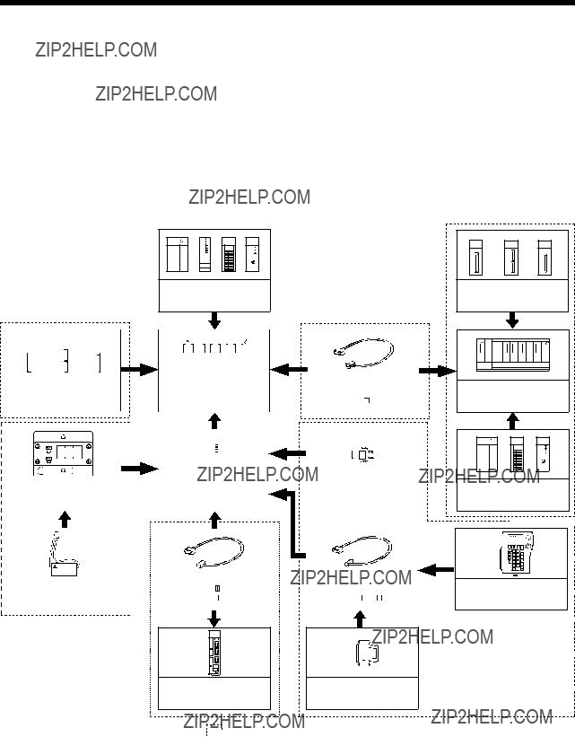
1.3.2 Q173HCPU System overall configuration
Motion CPU control module
CPU base unit
(Q3 B)
B)

100/200VAC
USB
 Input/output (Up to 256 points)
Interrupt signals (16 points)
Personal Computer
IBM PC/AT
Battery holder unit Q170HBATC
Teaching
 /A31TU-DN
Cable for the teaching unit
 CBL
CBL M(-A))
SSC I/F Communication cable (Q170CDCBL M/
M/
Q170BDCBL M)
M)
SSC I/F Card/Board
 0BD-PCF)
PManual pulse generator  3/module
Serial absolute synchronous encoder cable (Q170ENCCBL M)
M)
ESerial absolute synchronous encoder 2/module (Q170ENC)(Up to 6 modules)
Panel Personal Computer (WinNT/Win98/Win2000/WinXP) Computer link SSC
Extension base unit (Q6 B)
B)
UP to 7 extensions
M MM M
E EE E
 B
B
External input signals of servo amplifier
 Proximity dog
 Upper stroke limit
 Lower stroke limit
 /A31TU-DN
1 - 12

1 OVERVIEW
 CAUTION
 Construct a safety circuit externally of the Motion controller or servo amplifier if the abnormal operation of the Motion controller or servo amplifier differ from the safety directive operation in the system.
 The ratings and characteristics of the parts (other than Motion controller, servo amplifier and servomotor) used in a system must be compatible with the Motion controller, servo amplifier and servomotor.
 Set the parameter values to those that are compatible with the Motion controller, servo amplifier, servomotor and regenerative resistor model and the system application. The protective functions may not function if the settings are incorrect.
 When a teaching unit is used, the cable for the teaching unit is necessary between the Motion CPU
1 - 13
1 OVERVIEW
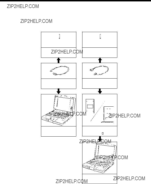
1.3.3 Q172HCPU System overall configuration
Motion CPU control module
CPU base unit
(Q3 B)
B)

100/200VAC
USB
 Input/output (Up to 256 points)
Interrupt signals (16 points)
Personal Computer
IBM PC/AT
Battery holder unit Q170HBATC
Teaching
 /A31TU-DN
Cable for the teaching unit
 CBL
CBL M(-A))
PManual pulse generator  3/module
Serial absolute synchronous encoder cable (Q170ENCCBL M)
M)
ESerial absolute synchronous encoder  2/module (Q170ENC) (Up to 4 modules)
Extension base unit (Q6 B)
B)
UP to 7 extensions
 B
B
External input signals of servo amplifier
 Proximity dog
 Upper stroke limit
 Lower stroke limit
 /A31TU-DN
1 - 14

1 OVERVIEW
 CAUTION
 Construct a safety circuit externally of the Motion controller or servo amplifier if the abnormal operation of the Motion controller or servo amplifier differ from the safety directive operation in the system.
 The ratings and characteristics of the parts (other than Motion controller, servo amplifier and servomotor) used in a system must be compatible with the Motion controller, servo amplifier and servomotor.
 Set the parameter values to those that are compatible with the Motion controller, servo amplifier, servomotor and regenerative resistor model and the system application. The protective functions may not function if the settings are incorrect.
 When a teaching unit is used, the cable for the teaching unit is necessary between the Motion CPU
1 - 15

1 OVERVIEW
1.3.4Software packages
(1)Software packages
(a)Operating system software packages
(b) Integrated
(2) Operating environment of personal computer
1 - 16
1 OVERVIEW
It is necessary the following capacity depending on the installed software.
in the United States and/or other countries.
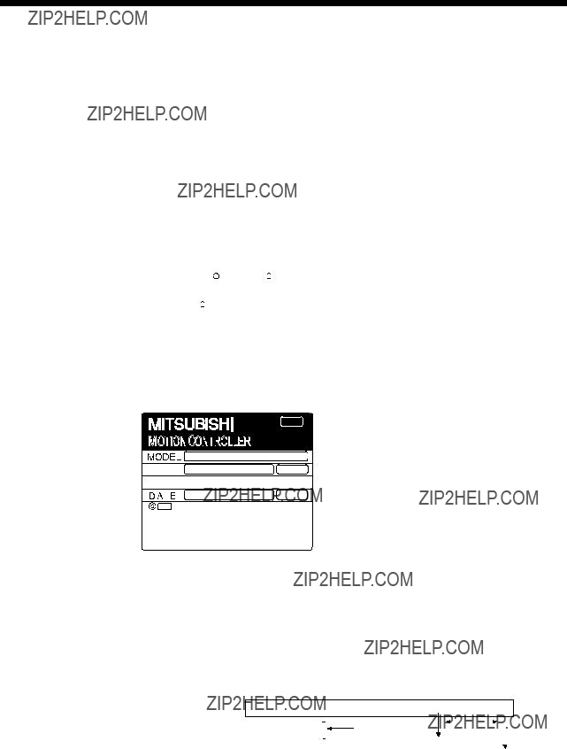
(3)Operating system(OS) type/version
(a)Confirmation method in the operating system(OS)
Example) When using the Q173HCPU, SV13 and version A.
1)
2)
3)A
(b)Confirmation method in the  P
P
The operating system(OS) type/version of the connected CPU is displayed on the installation screen of the  P.
P.
1 - 17

1 OVERVIEW
(4) Relevant software packages
(a) PLC software package
POINT
(1)When the operation of Windows is not unclear in the operation of this software, refer to the manual of Windows or
(2)The screen might not be correctly displayed depending on the system font size of WindowsNT R 4.0/Windows R 98/Windows R 2000/Windows R XP.
Be sure to use the small size fonts.
1 - 18

1 OVERVIEW
1.3.5Restrictions on motion systems
(1)It is not allowed to use the Motion CPU as the control CPU of a module installed on the QA1S6 B extension base unit. PLC CPU must be used as the control CPU.
(2)Motion CPU module cannot be used as standalone module. It must always be used in combination with the PLC CPU module (version that supports Multiple CPU systems). Moreover, it must be installed on the right side of PLC CPU module. PLC CPU module cannot be installed in a position to the right of Motion CPU module.
(3)Personal computer CPU unit must be installed on the right side of Motion CPU module. Motion CPU module cannot be installed in a position to the right of personal computer CPU unit.
(4)Make sure to use the PLC CPU module in the "Q mode."
(5)Motion CPU module cannot be set as the control CPU of intelligent function module or Graphic Operation Terminal (GOT).
(6)SSCNET cable which connects the Motion CPU and servo amplifier, and the
teaching unit connecting cable which connects the Motion CPU and A31TU-  /A31TU-DN
(7)Motion CPU module is one module element of Q series multiple PLC system. It must be set the parameters of Q series multiple PLC system for each PLC CPU. Motion CPU module must also be set to support the Multiple CPU system in the system settings.
(8)Make sure to use the Motion CPU as the control CPU of motion modules dedicated for Motion CPU (e.g., Q172LX,
(9)When a Multiple CPU system is configured, make sure to configure the modules so that the total current consumption of individual modules on the CPU base does not exceed the 5VDC output capacity of power supply module.
(10)Motion modules (Q172LX, Q172EX, Q173PX) is to do selection whether to be necessary referring to the "3. DESIGN" of the "Q173HCPU/Q172HCPU User's Manual" for the system design.
1 - 19

1 OVERVIEW
(11)Installation position of the
(12)When combining the
However, all the operating system software are SV43, there is no restriction for the combination of Motion CPU.
1
2
3
4
Installation example of Motion CPU
 CPU.
CPU.
 HCPU.
HCPU.
 CPU.
CPU.
(13)When the operation cycle is 0.4[ms], set the system setting as the axis select switch of servo amplifier "0 to 7".
If the axis select switch of servo amplifier "8 to F" is set, the servo amplifiers are not recognized.
1 - 20

2 MULTIPLE CPU SYSTEM
2. MULTIPLE CPU SYSTEM
2.1 Multiple CPU System
2.1.1 Overview
Multiple (up to 4 modules) PLC CPUs and Motion CPUs are installed to the CPU base unit, and each CPU controls the I/O modules and intelligent function modules of the CPU base unit/extension base unit slot by slot in the Multiple CPU system.
Each Motion CPU controls the servo amplifiers connected by SSCNET cable.
(2)Distributed system configuration
(a)By distributing such tasks as servo control, machine control and information control among multiple processors, the flexible system configuration can be realized.
(b)You can increase the number of control axes by using a multiple Motion CPUs. It is possible to control up to 96 axes by using three Q173HCPUs.
(c)You can reduce the PLC scan time of the overall system by using a multiple PLC CPUs and distributing the PLC control load among them.
(3)Communication among the CPUs in the Multiple CPU system
(a)Transmission of data among the CPUs in the Multiple CPU system is performed automatically using the multiple CPU automatic refresh function. This makes it possible to use the device data of the other CPUs as the device data of the self CPU.
(b)You can access the device data and start the Motion SFC program (SV13/SV22)/Motion program (SV43) from the PLC CPU to the Motion CPU by Motion dedicated PLC instruction.
2 - 1

2 MULTIPLE CPU SYSTEM
2.1.2 Installation of PLC CPU and Motion CPU
Up to a total four PLC CPUs and Motion CPUs can be installed in the CPU base unit, in the four slots starting from the CPU slot (the slot located to the immediate right of the power supply module) to slot 2 in series.
There must be no
When two or more Motion CPUs are installed, they are installed together in the slots provided to the right of one or more PLC CPUs. (PLC CPU cannot be installed to the right of a Motion CPU.)
(1) When the high performance model PLC CPU is used.
Number of
CPUs
2
3
4
Installation positions of PLC CPUs/Motion CPUs
(2) When the basic model PLC CPU is used.
Multiple CPU system up to 3 modules (PLC CPU 1, Motion CPU
 1, Personal computer CPU
 1).
1).
2 - 2

2 MULTIPLE CPU SYSTEM
2.1.3 Precautions for using Q series I/O modules and intelligent function modules
(1) Modules controllable by the Motion CPU
I/O modules (QX , QY
, QY , QH
, QH , QX
, QX Y
Y , Q6
, Q6 AD
AD , Q6
, Q6 DA
DA , interrupt module (QI60) and motion modules (Q172LX, Q172EX, Q173PX) can be controlled by the Motion CPU.
(2)Compatibility with the Multiple CPU system
(a)All I/O modules (QX , QY
, QY , QH
, QH , QX
, QX Y
Y , Q6
, Q6 AD
AD , Q6
, Q6 DA
DA ) support the Multiple CPU system.
(b)The interrupt module (QI60), which is currently not subject to function upgrade, supports the Multiple CPU system.
(c)The intelligent function modules support the Multiple CPU system only when their function version is B or later. These modules cannot be controlled by the Motion CPU, so be sure to use the PLC CPU as a control CPU.
(d)All motion modules (Q172LX, Q172EX, Q173PX) support the Multiple CPU system. These modules cannot be controlled by the PLC CPU, so be sure to use the Motion CPU as a control CPU.
(3)Access range from a
(a)The Motion CPU can access only the modules controlled by the self CPU. It cannot access the modules controlled by other CPUs.
(b)Access range from a
REMARK
???The function version of an intelligent function module can be checked on the rated plate of the intelligent function module or in the GX Developer's system monitor product information list.
???Refer to the "Q173HCPU/Q172HCPU User's Manual" for the model name which can be controlled by the Motion CPU.
2 - 3
2 MULTIPLE CPU SYSTEM
2.1.4Modules subject to installation restrictions
(1)Modules subject to installation restrictions in the Motion CPU are sown below. Use within the restrictions listed below.
(a) SV13/SV22
(b) SV43
(2)Modules controlled by a Motion CPU cannot be installed in the extension base unit QA1S6 B. Install them in the CPU base unit Q3
 B or extension base unit Q6
 B.
B.
2 - 4

2MULTIPLE CPU SYSTEM
(3)A total of eight base units including one CPU base unit and seven extension base units can be used. However, the usable slots (number of modules) are limited to 64 per system including vacant slots. If a module is installed in slot 65 or subsequent slot, an error (SP. UNIT LAY ERROR) will occur. Make sure all modules are installed in slots 1 to 64. (Even when the total number of slots provided by the CPU base unit and extension base units exceeds 65 (such as when six
2 - 5

2 MULTIPLE CPU SYSTEM
2.1.5Processing time of the Multiple CPU system
(1)Processing of the Multiple CPU system
Each CPU module of the Multiple CPU system accesses to the modules controlled by self CPU with which the CPU base unit or extension base unit is installed, and the other CPU through the bus (base unit patterns and extension cables). However, a multiple CPU module cannot use the bus simultaneously. When a multiple CPUs have accessed the bus simultaneously, the CPUs which performed buss access later remain in "waiting state" until the CPU currently using the bus completes its processing. In a Multiple CPU system, the above waiting time (duration while a CPU remains in waiting state) causes an I/O delay or prolonged scan time.
(2) When the waiting time becomes the longest
In the Multiple CPU system, the wait time of self CPU becomes the longest in the following conditions:
???When is using a total of four PLC CPUs/Motion CPUs are used in the Multiple CPU system.
???When the extension base units are used.
???When the intelligent function modules handling large volumes of data are installed in the extension base unit(s).
???When a total of four CPUs are used and the four CPUs have simultaneously accessed a module installed in an extension base unit.
???When there are many automatic refresh points between a PLC CPU and a Motion CPU.
(3)When shortening the processing time of the Multiple CPU system
The processing time of the Multiple CPU system can be shortened in the following methods:
???Install all modules with many access points such as MELSECNET/10(H) and
???Control all modules with many access points such as MELSECNET/10(H) and
???Reduce the number of refresh points of MELSECNET/10(H),
???Reduce the number of automatic refresh points of the PLC CPUs/Motion CPUs.
2 - 6

2 MULTIPLE CPU SYSTEM
2.1.6 How to reset the Multiple CPU system
With the Multiple CPU system, resetting the PLC CPU of CPU No. 1 resets the entire system.
When the PLC CPU of CPU No. 1 is reset, the CPUs, I/O modules and intelligent function modules of all CPUs will be reset.
To recover any of the CPUs in the Multiple CPU system that generated a CPU stop error, reset the PLC CPU of CPU No. 1 or restart the power (i.e., turning the power ON, OFF and then ON).
(If the PLC CPUs or Motion CPUs of CPU Nos. 2 through 4 generated a CPU stop error, they cannot be recovered by resetting the corresponding CPU.)
Power supply
Qn(H) Q173H Q173H Q173H
CPU CPU CPU CPU
These CPUs must not be reset. If one of them is reset, all CPU
in the Multiple CPU system generate a MULTI CPU DOWN error.
CPU No. 1 can reset the entire Multiple CPU system.
POINT
(1)In a Multiple CPU system, the PLC CPUs/Motion CPUs of CPU No. 2, 3 or 4 cannot be reset individually.
When a PLC CPU or Motion CPU of CPU No. 2, 3 or 4 is reset while the Multiple CPU system is operating, the other CPUs generate a MULTI CPU DOWN error (error code: 7000) and the entire system stops.
Note that depending on the timing at which the PLC CPU or Motion CPU of CPU No. 2, 3 or 4 is reset, the PLC CPU of a the other CPU may stop due to an error other than MULTI CPU DOWN.
(2)Resetting CPU No. 2, 3 or 4 generates a MULTI CPU DOWN error regardless of the operation mode set in the Multiple CPU Settings tab. (Stop/continue all CPUs upon error in CPU No. 2, 3 or 4.) (Refer to Section 2.1.7 for the setting of operation mode in Multiple CPU Settings.)
2 - 7
2 MULTIPLE CPU SYSTEM
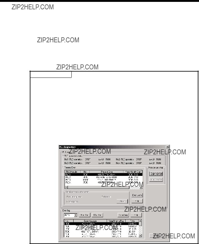
2.1.7Processing at a CPU DOWN error occurrence by a PLC CPU or Q173HCPU/ Q172HCPU
In the Multiple CPU system, the system operates differently when CPU No. 1 generated a CPU DOWN error as compared with when CPU No. 2, 3 or 4 did.
(1)When CPU No. 1 generated a CPU DOWN error
(a)When the PLC CPU of CPU No. 1 generated a CPU DOWN error, all PLC CPU/Q173HCPU/Q172HCPU of CPU Nos. 2, 3 and 4 generate a MULTI CPU DOWN error (error code: 7000) and the Multiple CPU system stops.
(b)Recover the system using the procedure below:
1)Check the cause of the error that occurred in CPU No. 1 using the PC diagnostic function of GX Developer.
2)Remove the cause of the error.
3)Reset the PLC CPU of CPU No. 1 or restart the power.
Resetting the PLC CPU of CPU No. 1 or restarting the power resets all
CPUs in the Multiple CPU system and the system is recovered.
(2) When CPU No. 2, 3 or 4 generated a CPU DOWN error
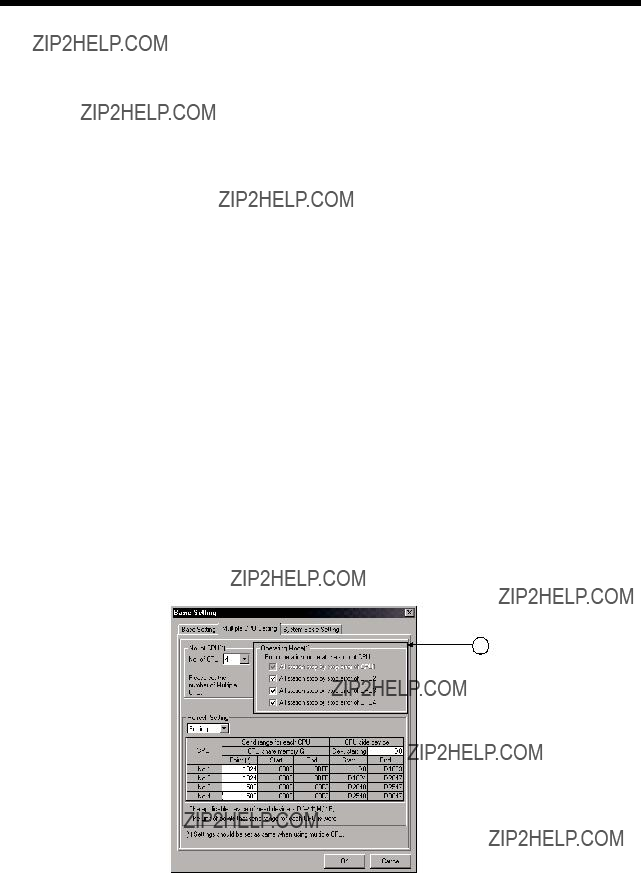
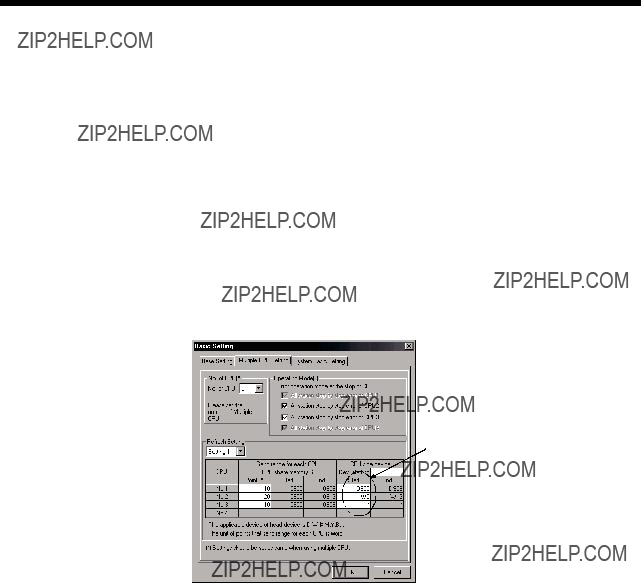
If the PLC CPU, Q173HCPU or Q172HCPU of CPU No. 2, 3 or 4 generated a CPU DOWN error, the entire system may or may not stop depending on the setting of "Operation Mode" in the Multiple CPU Settings tab.
By default value, all CPUs will stop when any of the CPUs generates a CPU stop error. If you do not wish to stop all CPUs following an error generated in the PLC CPU, Q173HCPU or Q172HCPU of a specific CPU or CPUs, click and uncheck the CPU or CPUs that will not stop all CPUs upon generating an error. (See arrow A.)
2 - 8
2MULTIPLE CPU SYSTEM
(a)When a CPU DOWN error occurs in the CPU of the CPU in a checked "Stop all CPUs upon error in CPU No. n" item, all PLC CPU/Q173HCPU/ Q172HCPU of the other CPUs will generate a MULTI CPU DOWN error (error code: 7000) and the Multiple CPU system will stop.
(b)When a CPU DOWN error occurs in the CPU of the PLC in an unchecked "Stop all CPUs upon error in CPU No. n" item, all CPUs of the other CPUs will generate a MULTI CPU ERROR (error code: 7020) and continue their operation.
POINT
Therefore, the system may enter a MULTI CPU DOWN mode after detecting the CPU DOWN error in the CPU generating a MULTI CPU DOWN error, instead of the error in the CPU that generated the CPU DOWN error in the first place. In this case, the common
When recovering the system, remove the cause of the error present in the CPU not stopped by a MULTI CPU DOWN error.
In the screen below, the cause of the error present in CPU No. 2, which does not have a MULTI CPU DOWN error, should be removed.
2 - 9

2MULTIPLE CPU SYSTEM
(c)Use the following procedure to recover the system:
1)Check the CPU generating the error and cause of the error using the PC diagnostic function of GX Developer.
2)If the error occurred in a Q173HCPU/Q172HCPU and the error code is 10000, check the cause of the error using error list of  P.
P.
3)Remove the cause of the error.
4)Reset the PLC CPU of CPU No. 1 or restart the power.
5)Resetting the PLC CPU of CPU No. 1 or restarting the power resets all CPUs in the Multiple CPU system and the system will be recovered.
(3) Operation at a Motion CPU error
Operations at a Motion CPU error are shown below.
2 - 10

2 MULTIPLE CPU SYSTEM
2.2 Starting Up the Multiple CPU System
This section describes a standard procedure to start up the Multiple CPU system.
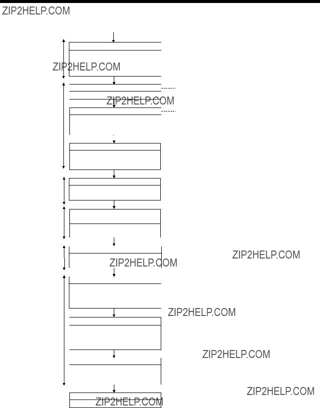
2.2.1 Startup Flow of the Multiple CPU System
Multiple CPU system
Multiple CPU system design
Clarify control/function executed by each
CPU.
Device application and assignment
Secure the refresh points continuously for automatic refresh of device data.
Module select
Select modules to be used in the Multiple CPU system.
PLC CPU
Motion CPU
Module install
Install the selected modules to the CPU base unit or extension base unit.
???Refer to Section 2.3 for automatic refresh function of device data.
???Refer to the "Q173HCPU/Q172HCPU User's Manual" for module select.
???Refer to the "Q173HCPU/Q172HCPU User's Manual" for install method or install position of modules.
???Refer to Section 2.1.4 of the "Q173HCPU/ Q172HCPU User's Manual" for restrictions of module install.
PLC CPU
Motion CPU
PLC CPU
GX developer start
Start the GX Developer (Ver.6 or later).
Parameters, etc. create
Create the parameter setting such as Multiple CPU setting and control CPU setting, and the PLC programs.
Connect between the personal computer and PLC CPU
Connect between the personal computer running GX Developer and PLC CPU No.1 by USB cable.
Connect between the personal computer and Motion CPU
Connect between the personal computer running  P
P
When the USB cable is used to communicate with the Motion CPU, connect the cable to any one of the PLC CPU/Motion CPU in the Multiple CPU system.
Multiple CPU system power ON
Turn ON the power of Multiple CPU system in the following state of PLC CPU.
RUN/STOP switch : STOP
RESET/L.CLR switch : OFF
???Refer to the GX Developer manual for GX Developer start.
???Create the parameters for CPU No. 1 to 4 and PLC programs.
???Refer to the "QCPU User's Manual" (Function Explanation/Program Fundamentals)" for PLC settings.
1)
2 - 11
2 MULTIPLE CPU SYSTEM
PLC CPU
Motion CPU
PLC CPU
PLC CPU
Motion CPU
PLC CPU
PLC CPU
Motion CPU
1)
Write to the PLC CPU
Write the parameters and PLC programs to the PLC CPU (CPU No.1).
Set the connect destinations of PLC CPU (CPU No. 2 to 4), and write them.

Start the 
System settings and program, etc. create
Create the system settings, servo data and Motion SFC program (SV13/SV22)/
Motion program (SV43).
Write to the Motion CPU
Write the system settings, servo data and Motion SFC program (SV13/SV22)/
Motion program (SV43).
PLC CPU (CPU No.1) reset
Set the RESET/L.CLR switch to RESET position.
Set RUN/STOP switch for all CPUs to RUN position.
Set the RUN/STOP switch for each CPU (CPU No.1 to 4) to RUN position.
Release PLC CPU (CPU No.1) reset
Change back the RESET/L.CLR switch to OFF position and release the reset.
Check of state for all CPUs
Check whether all CPUs in the Multiple CPU system become RUN state/error by reset release of the PLC CPU (CPU No.1).
Check and correct the error details
If an error has occurred, check and correct the error details using the PC diagnostic function of GX developer and error list monitor of  P.
P.
Each CPU debug
Execute the individual debug of PLC CPU/Motion CPU (CPU No. 1 to 4) and debug as the Multiple CPU system.
Actual operation
Actual operation Check in the automatic operation.
???Refer to the help for operation of  P.
P.
???Refer to Section 3.1 for system settings.
???Refer to the Programming Manual of each operating system software for details of program.
(Note) : Installation of the operating system software is required to the Motion CPU module before start of the Multiple CPU system.
Refer to Chapter 5 of the "Q173HCPU/Q172HCPU User's Manual" for installation of the Motion CPU operating system software.
2 - 12
2 MULTIPLE CPU SYSTEM
2.3 Communication between the PLC CPU and the Motion CPU in the Multiple CPU System
The following tasks can be performed between the PLC CPU and the Motion CPU in the Multiple CPU system.
???Data transfer between CPUs by the automatic refresh function of the shared CPU memory
???Control instruction from the PLC CPU to Motion CPU by the Motion dedicated Instructions
???Reading/writing device data from the PLC CPU to Motion CPU by the dedicated instruction
2.3.1Automatic Refresh Function of The Shared CPU Memory
(1)Automatic refresh function of the shared CPU memory
(a)The automatic refresh function of the shared CPU memory is executed automatically the data transfer between CPUs in the Multiple CPU system during END processing in the PLC CPU or during main cycle processing (free time except motion control) in the Motion CPU.
When the automatic refresh function is used, the data in the device memory of the other CPU is read automatically, so the device data of other CPU can be used as the device data of self CPU.
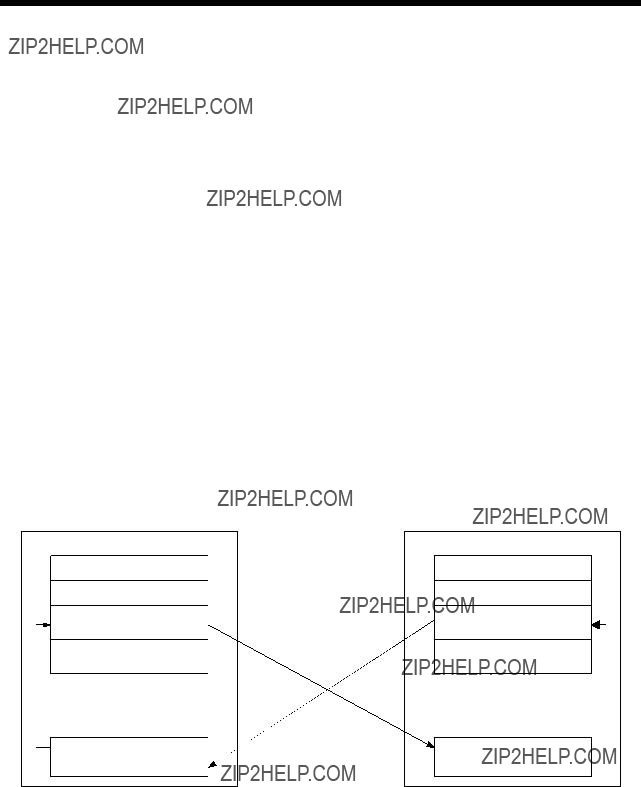
The diagram below illustrates the automatic refresh operation involving 32 points (B0 to B1F) for the PLC CPU of CPU No.1 and 32 points (B20 to B3F) for the Motion CPU of CPU No.2.
CPU No.1 (PLC CPU)
Shared CPU memory
Self CPU operation data area
System area
Automatic refresh area
1)Written via END processing of CPU No.1
3)Reading via main cycle processing of CPU No.2
CPU No.2 (Motion CPU)
Shared CPU memory
Self CPU operation data area
System area
Automatic refresh area
2)Written via main cycle processing of CPU No.2
Processing details of CPU No.1 (PLC CPU) at the END processing.
1): Data of transmitting devices B0 to B1F for CPU No.1 is transferred to the automatic refresh area of shared memory in the self CPU.
4): Data in the automatic refresh area of shared memory in CPU No.2 is transferred to B20 to B3F in the self CPU.
2 - 13
2 MULTIPLE CPU SYSTEM
Processing details of CPU No.2 (Motion CPU) at main cycle processing.
2): Data of transmitting devices B20 to B3F for CPU No.2 is transferred to the automatic refresh area of shared memory in the self CPU.
3): Data in the automatic refresh area of shared memory in CPU No.1 is transferred to B0 to B1F in the self CPU.
By the above operations, the data written to B0 to B1F in CPU No.1 can be read as B0 to B1F of CPU No.2, while the data written to B20 to B3F in CPU No.2 can be read as B20 to B3F of CPU No.1. B0 to B1F of CPU No.1 can be read or written freely using CPU No.1, but B20 to B3F correspond to the refresh area for the data of CPU No.2 and can only be read, not written, by CPU No. 1. Similarly, B20 to B3F of CPU No.2 can be read or written freely using CPU No.2, but B0 to B1F correspond to the refresh area for the data of CPU No.1 and thus can only be read, not written, by CPU No.2.
(b)Executing the automatic refresh function
The automatic refresh function can be executed regardless of whether the applicable PLC CPU and Motion CPU are in the RUN or STOP state. When a CPU DOWN error will occur in the PLC CPU or Motion CPU, the automatic refresh function is not executed.
When one CPU generated a CPU DOWN error, the other CPU free from CPU DOWN error retains the data saved immediately before the CPU DOWN error occurred. For example, if CPU No.2 generated a CPU DOWN error while B20 was ON in the operation block diagram in (a), B0 of CPU No.1 remains ON. If necessary, interlocking is performed using
(c)To execute the automatic refresh function, for the Motion CPU the number of transmitting points for the CPU and the devices whose data is stored (devices to which the automatic refresh function is executed) must be set in Multiple CPU Settings of System Settings. For the PLC CPU, the applicable parameters must be set identically in Multiple CPU Settings of PC parameters.
 CAUTION
 If necessary, perform interlocking during the execution of the automatic refresh function using other CPU DOWN detection signals M9244 to M9247.
2 - 14
2MULTIPLE CPU SYSTEM
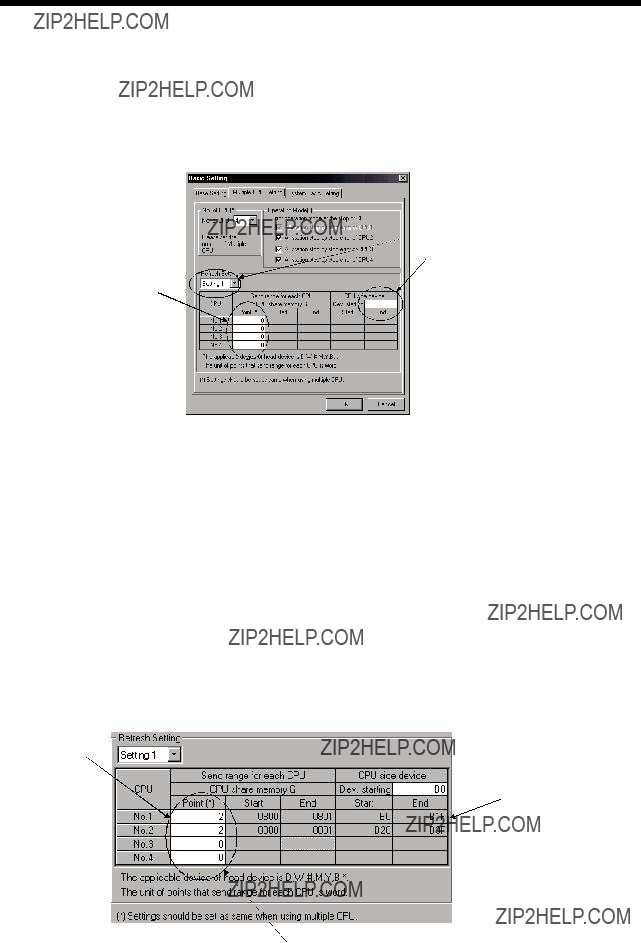
(2)Automatic refresh settings 1 (Automatic setting)
(a)When executing the automatic refresh function of shared CPU memory, set the number of each CPU's transmitting points and devices in which data is to be stored using Multiple CPU Settings of System Settings.
Refer to the "QCPU User's Manual (Functions Explanation/Program Fundamentals)" about the setting of the PLC CPU.
???Select the setting No..
???Set the first device No. from which the automatic refresh function is executed.
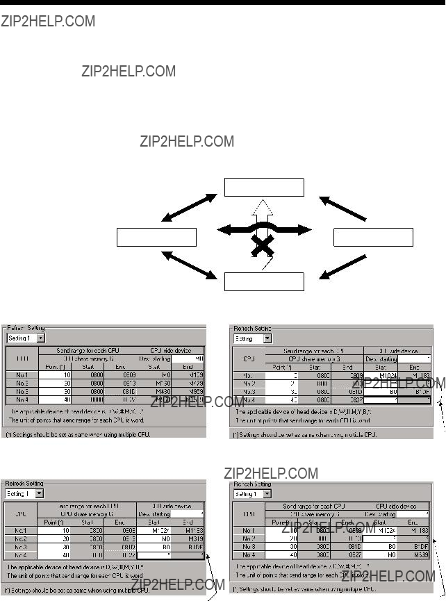
(b)Setting number selection/send range (refresh range) for each CPU
1)The refresh setting of four ranges can be set by setting selection.
For example, ON/OFF data may be refreshed using
2)The number of points in the shared CPU memory set in units of 2 points (2 words) is set in the range for each CPU. (2 points if word device is specified for the
Assume that 32 points (B0 to B1F) of CPU No.1 and 32 points (B20 to B3F) of CPU No.2 are to be refreshed. Since one point in the shared CPU memory corresponds to 16
3)The maximum number of transmitting points combining all four ranges is 2k words per CPU (PLC CPU or Motion CPU) or 8k points (8k words) for all CPUs.
???2k points (2k words) per CPU
???8k points (8k words) for all CPUs
???Set in units of
2 points (2 words).
???Setting two points in shared CPU memory and specifying the bit device for the CPU- side device creates 32 bit- device points.
??? Data in CPU No.3 and 4 is not refreshed since the number of points is set to 0.
2 - 15

2MULTIPLE CPU SYSTEM
4)The shared CPU memory to be occupied during execution of the automatic refresh function covers all areas corresponding to settings 1 to 4.
When the number of transmitting points is set, the first and last addresses of the shared CPU memory to be used are indicated in hexadecimals.
The CPU for which the number of transmitting points is set in settings 1 and 2 use the last address of shared CPU memory in setting 2. (In the example below, CPU No.1 and No.2 are using the area up to 811H, while CPU No.4 is using the area up to 821H.)
The CPU for which the number of transmitting points is set only in setting 1 use the last address of shared CPU memory in setting 1. (In the example below, CPU No.3 is using the last address in setting 1).
???Send range for CPU No.1
 ??? Last address of
??? Last address of the shared CPU memory for each CPU
5)Set the same number of transmitting points for all CPUs in the Multiple CPU system.
If any of the CPUs has a different number of transmitting points, a PARAMETER ERROR will be occurred.
(c)
The following devices can be used for automatic refresh. (Other devices cannot be set in  P.)
P.)
1)As for the
Set a device number that ensures enough devices for the set transmitting points.
When bit device is specified for the
2 - 16

2 MULTIPLE CPU SYSTEM
2)Set the
??? Settings 1 to 4 may use different devices.
If the device ranges do not overlap, the same device may be used for settings 1 to 4.
Setting 1: Link relay
??? Settings 1 to 4 may use different devices.
Setting 2: Link register
??? The same device may be used for settings 1 to 4.
In setting 1 shown to the left, 160 points from B0 to B9F are used. Therefore, setting 3 can use device No. after BA0. Device numbers may not overlap even partially, such as specifying B0 to B9F in setting 1 and B90 to B10F in setting 3.
Setting 3: Link relay
??? The first and last addresses are calculated automatically in  P.
P.
2 - 17

2 MULTIPLE CPU SYSTEM
???The devices in settings 1 to 4 can be set individually for each CPU. For example, you may set link relay for CPU No.1 and internal relay for CPU No.2.
Refresh settings of CPU No.1
??? Set the same number of points for all CPUs.
Refresh settings of CPU No.2
???When the
???When the
same as that for CPU No.2.
2 - 18

2MULTIPLE CPU SYSTEM
3)The block diagram below illustrates the automatic refresh operation over four ranges of setting 1: link relay (B), setting 2: link register (W), setting 3: data register (D), and setting 4: internal relay (M).
CPU No.1
CPU No.2
receiving data (No.4)
CPU No.3 receiving data (No.4)
CPU No.4  receiving data (No.4)
Write during END processing
Shared CPU memory
2 - 19
2MULTIPLE CPU SYSTEM
(3)Automatic refresh settings 2 (Manual setting)
(a)When the automatic refresh setting (Manual setting) of Motion CPU is used, there are the following advantages.
1)A device setting which executes the automatic refresh setting between the PLC CPU and Motion CPU can be performed flexibly.
2)Because it is made not to execute the automatic refresh setting between the Motion CPU using a dummy setting, it is not necessary to use the user device for the automatic refresh vainly, and a main cycle can also be shortened.
3)It is possible to execute the automatic refresh of Motion device (#) to the PLC CPU directly. Similarly, it is possible to execute the automatic refresh for data of the PLC CPU to the Motion device (#) directly.
Refer to the "QCPU User's Manual (Functions Explanation/Program
Fundamentals)" about the setting for the PLC CPU.
??? The first device can be arbitrarily set up for every CPU. "DUMMY(*)" can be set to the first device except the self CPU.
 ??? The motion device (#) can be set as a first device.
(b)Setting selection/send range (refresh range) for each CPU
1)The refresh setting of four ranges can be set by setting selection.
For example, ON/OFF data may be refreshed using
2)The number of points in the shared CPU memory is set in units of 2 points (2 words) is set in the send range for each CPU. (2 points if word device is specified for the
Data of the CPU for which "0" is set as the number of points representing the transmitting range of the CPU may not be refreshed.
3)The maximum number of transmitting points combining all four ranges is 2k words per CPU (PLC CPU or Motion CPU) or 8k points (8k words) for all CPUs.
4)If "*" is set as the first device setting column A of each automatic refresh setting, the first device for every CPU can be arbitrarily set up by the user in the column of B.
2 - 20

2MULTIPLE CPU SYSTEM
5)"DUMMY" setting can be set to the first device column B of the automatic refresh setting. ("DUMMY" setting cannot be set to the self CPU.) "DUMMY" setting should set "*" as the first devise column B. The self CPU does not execute the automatic refresh to the other CPU which carried out "DUMMY(*)" setting.
A
B
??? A white portion can be set.
6)Set the same number of transmitting points for all CPUs in the Multiple CPU system.
If any of the CPUs has a different number of transmitting points, a PARAMETER ERROR will be occurred.
2 - 21

2MULTIPLE CPU SYSTEM
(c)
The following devices can be used for automatic refresh. (Other devices cannot be set in  P.)
P.)
???Self CPU (CPU No.2) Refresh setting 1
??? If the device No. does not overlap, it is right.
 ??? The device of CPU No.4 at setting 1 is not refreshed by the CPU No.2.
???Self CPU (CPU No.2) Refresh setting 2
??? If the device No. does not overlap, it is right.
 ??? The device of CPU No.4 at setting 2 is not refreshed by the CPU No.2.
2 - 22
2 MULTIPLE CPU SYSTEM
[Dummy setting]
Usually, the automatic refresh setting is executed between PLC CPU and Motion CPU for the instructions to each Motion CPU and the monitor of a state by the PLC CPU at the time of operation. However, the automatic refresh is not necessary between each Motion CPU. In this case, because it is made not to execute the automatic refresh setting between the Motion CPU using a dummy setting, it is not necessary to use the user device for the automatic refresh vainly, and a main cycle can also be shortened.
Example of the automatic refresh setting using the "Dummy setting" is as follows.
Motion CPU No.2
Read data of
CPU No.3
??? This part is not refreshed so that a dummy setting.
Motion CPU No.4
Read data of CPU No.3
???PLC CPU (CPU No.1) Automatic refresh setting 1
???Motion CPU (CPU No.2) Automatic refresh setting 1
???Motion CPU (CPU No.3) Automatic refresh setting 1
???The device of CPU No.2 and No.4 are not refreshed by the CPU No.3.
???Motion CPU (CPU No.4) Automatic refresh setting 1
Although the example of a setting is the case of the automatic refresh setting 1, the automatic refresh setting 2 - 4 can be also set similarly.
2 - 23
2MULTIPLE CPU SYSTEM
(4)The layout example of automatic refresh setting
The layout example of automatic refresh when Read/Write does a Motion dedicated device in the Motion CPU with PLC CPU is shown below.
(a)SV13
??? Overall configuration
to
User device (4352 points)
Table of the data registers
to
User device (7392 points)
2 - 24
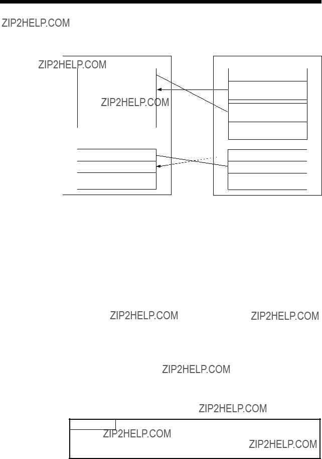
2MULTIPLE CPU SYSTEM
1)PLC CPU (1 module) + Motion CPU (1 module)
The outline operation and the automatic refresh setting are as follows.
CPU No.1 (PLC CPU)
Data registers
D0 Command device for
the Motion CPU (118 points)
D118 Monitor device for
the Motion CPU (640 points)
D758
D8191
CPU No.2 (Motion CPU)
Internal relays
M0
M2000 Monitor device
M3055 (1056 points)
 M3072 Command device M3839 (768 points)
M3840
M8191
 D640 Command device
(118 points)
D758
D8191
??? Automatic refresh setting 1
??? Automatic refresh setting 2
PLC CPU (CPU No.1)
Motion CPU (CPU No.2)
POINT
Although it has set up so that 32 axes may be assigned in the above assignment example, reduce the number of assignment automatic refresh points a part for the number of axes to be used.
2 - 25

2MULTIPLE CPU SYSTEM
2)PLC CPU (1 module) + Motion CPU (2 modules)
The outline operation and the automatic refresh setting are shown below.
CPU No.1 (PLC CPU)
the Motion CPU No.3
(640 points)
D1516
D8191
CPU No.2 (Motion CPU)
Internal relays
M0
CPU No.3 (Motion CPU)
Internal relays
2 - 26

2 MULTIPLE CPU SYSTEM
??? Automatic refresh setting 1
PLC CPU (CPU No.1)
Motion CPU (CPU No.2)
??? Automatic refresh setting 2
??? Automatic refresh setting 3
PLC CPU (CPU No.1)
Motion CPU (CPU No.2)
(Note) : A dummy setting is made so that an excessive device may not be refreshed in the Motion CPU No.2.
??? Automatic refresh setting 4
PLC CPU (CPU No.1)
Motion CPU (CPU No.2)
(Note) : A dummy setting is made so that an excessive device may not be refreshed in the Motion CPU No.2.
2 - 27

2 MULTIPLE CPU SYSTEM
(Note) : A dummy setting is made so that an excessive device may not be refreshed in the Motion CPU No.3.
??? Automatic refresh setting 2
Motion CPU (CPU No.3)
(Note) : A dummy setting is made so that an excessive device may not be refreshed in the Motion CPU No.3.
POINT
In the case of the combination "PLC CPU (1 module) + Motion CPU (3 modules)" with SV13, make all the devices of all the CPUs refresh as mentioned above because the setting that Read/Write is made of the PLC CPU cannot be executed.
2 - 28

2 MULTIPLE CPU SYSTEM
(b)SV22
??? Overall configuration
Table of the data registers
D8191
2 - 29
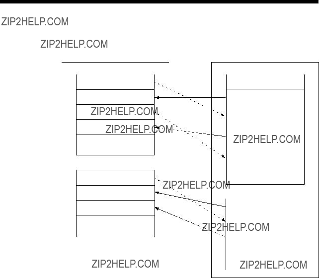
2MULTIPLE CPU SYSTEM
1)PLC CPU (1 module) + Motion CPU (1 module)
The outline operation and the automatic refresh setting are as follows.
D8191
2 - 30

2 MULTIPLE CPU SYSTEM
??? Automatic refresh setting 1
PLC CPU (CPU No.1)
Motion CPU (CPU No.2)
??? Automatic refresh setting 2
??? Automatic refresh setting 3
??? Automatic refresh setting 4
POINT
In the case of the combination "PLC CPU (1 module) + Motion CPU (2 modules)" with SV22, make all the devices of all the CPUs refresh as mentioned above because the setting that Read/Write is made of the PLC CPU cannot be executed.
2 - 31

2 MULTIPLE CPU SYSTEM
(c)SV43
???Overall configuration
Table of the internal relays
Table of the Data registers
to
User device (6502 points)
D8191
2 - 32
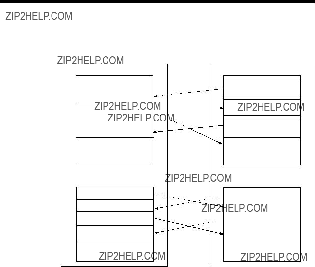
2MULTIPLE CPU SYSTEM
1)PLC CPU (1 module) + Motion CPU (1 module)
The outline operation and the automatic refresh setting are shown below.
CPU No.1 (PLC CPU)
M1824 Command device for
the Motion CPU (320 points)
CPU No.2 (Motion CPU)
Internal relays
M0
M2464
M8191
D1632
D8191
??? Automatic refresh setting 1
??? Automatic refresh setting 2
2 MULTIPLE CPU SYSTEM
??? Automatic refresh setting 3
PLC CPU (CPU No.1)
Motion CPU (CPU No.2)
??? Automatic refresh setting 4
PLC CPU (CPU No.1)
Motion CPU (CPU No.2)
POINT
Although it has set up so that 32 axes may be assigned in the above assignment example, reduce the number of assignment automatic refresh points a part for the number of axes to be used.
2 - 34

2MULTIPLE CPU SYSTEM
2)PLC CPU (1 module) + Motion CPU (2 modules)
The outline operation and the automatic refresh setting are as follows.
CPU No.1 (PLC CPU)
the Motion CPU No.3
(640 points)
D1516
D8191
CPU No.2 (Motion CPU)
Internal relays
M0
CPU No.3 (Motion CPU)
Internal relays
2 - 35

2 MULTIPLE CPU SYSTEM
??? Automatic refresh setting 1
PLC CPU (CPU No.1)
Motion CPU (CPU No.2)
??? Automatic refresh setting 2
??? Automatic refresh setting 3
PLC CPU (CPU No.1)
Motion CPU (CPU No.2)
(Note): A dummy setting (*) is made so that an excessive device may not be refreshed in the Motion CPU No.2.
??? Automatic refresh setting 4
PLC CPU (CPU No.1)
Motion CPU (CPU No.2)
(Note): A dummy setting (*) is made so that an excessive device may not be refreshed in the Motion CPU No.2.
2 - 36

2 MULTIPLE CPU SYSTEM
(Note): A dummy setting (*) is made so that an excessive device may not be refreshed in the Motion CPU No.2.
??? Automatic refresh setting 2
Motion CPU (CPU No.3)
(Note): A dummy setting (*) is made so that an excessive device may not be refreshed in the Motion CPU No.2.

2 MULTIPLE CPU SYSTEM
POINT
In the case of the combination "PLC CPU (1 module) + Motion CPU (3 modules)" with SV43, make all the devices of all the CPUs refresh as mentioned above because the setting that Read/Write is made of the PLC CPU can not be executed.
2 - 38
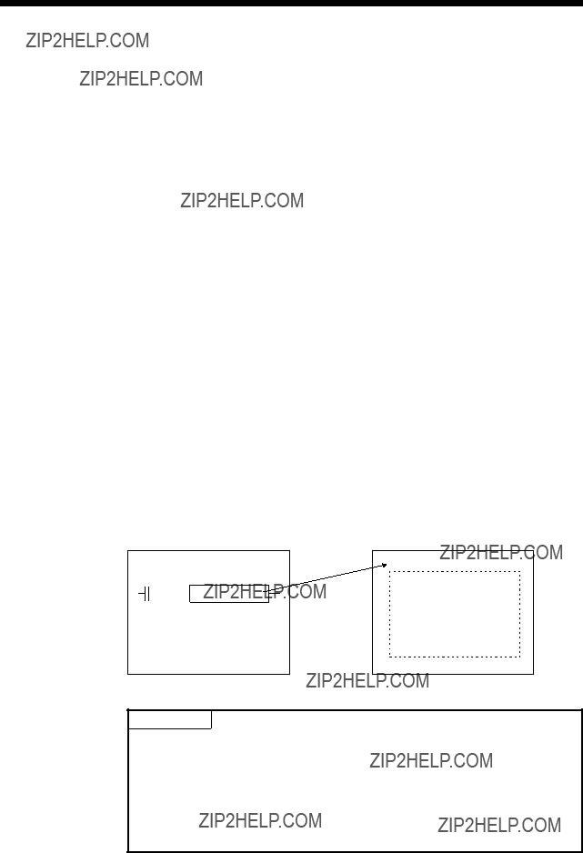
2 MULTIPLE CPU SYSTEM
2.3.2Control Instruction from the PLC CPU to The Motion CPU (Motion dedicated instructions)
Control can be instructed from the PLC CPU to the Motion CPU using the Motion dedicated PLC instructions listed in the table below.
Refer to the "Q173HCPU/Q172HCPU Motion controller (SV13/SV22) Programming Manual (Motion SFC)" or "Q173HCPU/Q172HCPU Motion controller (SV43) Programming Manual" for the details of each instruction.
(Control may not be instructed from the Motion CPU to another Motion CPU.)
By using the S(P).SFCS instruction of the Motion dedicated instruction, the Motion
SFC of the Motion CPU from the PLC CPU can be started.
POINT
One PLC CPU can execute a total of up to 32 "Motion dedicated instructions" and "dedicated instructions excluding the S(P).GINT" simultaneously.
When Motion dedicated instructions and dedicated instructions excluding the "S(P).GINT" are executed simultaneously, the instructions will be processed in the order received.
If the command which has not completed processing becomes 33 or more, an OPERATION ERROR (error code: 4107) will be occurred.
2 - 39
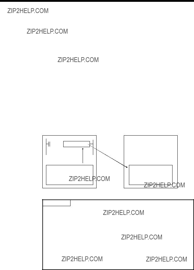
2 MULTIPLE CPU SYSTEM
2.3.3 Reading/Writing Device Data
Device data can be written or read to/from the Motion CPU by the PLC CPU using the dedicated instructions listed in the table below.
Refer to the "Q173HCPU/Q172HCPU Motion controller (SV13/SV22) Programming Manual (Motion SFC)" or "Q173HCPU/Q172HCPU Motion controller (SV43) Programming Manual for the details of each instruction.
(Data cannot be written or read to/from the PLC CPU by another PLC CPU, to/from the PLC CPU by the Motion CPU, or to/from a Motion CPU by another Motion CPU.)
For example, by using the S(P). DDWR dedicated instruction, the device data of the
PLC CPU can be written to the device data of the Motion CPU.
<Example>
Read device memory
POINT
(1)One PLC CPU can execute a total of up to 32 "Motion dedicated instructions" and "dedicated instructions excluding the S(P).GINT" simultaneously.
When Motion dedicated instructions and dedicated instructions excluding the S(P).GINT are executed simultaneously, the instructions will be processed in the order received.
If the command which has not completed processing becomes 33 or more, an OPERATION ERROR (error code: 4107) will be occurred.
(2)Data refresh via the S(P).DDRD/S(P).DDWR is not synchronized with data refresh via the automatic refresh function of shared CPU memory.
Do not issue S(P).DDRD/S(P).DDWR instructions to the devices whose data in shared CPU memory is being refreshed.
2 - 40

2 MULTIPLE CPU SYSTEM
2.3.4 Shared CPU Memory
Shared CPU memory is used to transfer data between the CPUs in the Multiple CPU system and has a capacity of 4096 words from 0H to FFFH.
Shared CPU memory has four areas: "self CPU operation data area", "system area", "automatic refresh area" and
When the automatic refresh function of shared CPU memory is set, the area corresponding to the number of automatic refresh points starting from 800H is used as the automatic refresh area.
The
If the number of automatic refresh points is 18 (12H points), the area from 800H to 811H becomes the automatic refresh area and the area after 812H becomes the user- defined area.
The diagram below shows the structure of shared CPU memory and accessibility from a PLC program.
REMARK
Use the MULTW instruction to write to the
 \G
\G ) to read the shared memory of the Motion CPU from the PLC CPU.
Use the MULTR instruction to read the shared memory of other CPU in the Motion CPU.
2 - 41

2MULTIPLE CPU SYSTEM
(1)Self CPU operation data area (0H to 1FFH)
(a)The following data of the self CPU are stored in the Multiple CPU system,
Table 2.1 Table of Contents Stored in the Self CPU Operation Data Area
(Note) : Refer to the corresponding special register for details.
(b)The self CPU operation data area is refreshed every time the applicable register has been changed.
However, the refresh timing may be delayed by up to the main cycle time. (It updates using idle time during motion control. The maximum main cycle time: several milliseconds to several hundred milliseconds).
(c)The data of the self CPU operation data area can be read from the PLC CPU of the other CPU by the FROM instruction.
However, since there is a delay in data update, use the data that has been read as an object for monitoring only.
(d)Self CPU operation data area used by Motion dedicated PLC instruction
(30H to 33H)
The complete status of the to self CPU high speed interrupt accept flag from CPUn is stored in the following address.
Table 2.2 Self CPU Operation data Area used by the Motion Dedicated PLC Instruction
2 - 42

2MULTIPLE CPU SYSTEM
(2)System area (200H to 7FFH)
This area is used by the operating systems (OS) of the PLC CPU/Motion CPU. OS uses this area when executing dedicated Multiple CPU communication instructions.
???System area used by Motion dedicated PLC instruction (204H to 20DH) The complete status is stored in the following.
Table 2.3 Table of System Area used by the Motion Dedicated PLC Instruction
Shared
memoryNameDescription address
The start accept flag is stored by the 1 to 32 axis, each bit.
(As for a bit's actually being set Q173HCPU : J1 to J32/ 204H(516) Start accept flag (Axis1 to 16)Q172HCPU : J1 to J8.)
OFF : Start accept flag usable
ON : Start accept flag disable
The speed changing flag is stored by the 1 to 32 axis, each bit.
(As for a bit's actually being set Q173HCPU : J1 to J32/ 206H(518) Speed changing flag (Axis1 to 16) Q172HCPU : J1 to J8.)
OFF : Start accept usable
ON : Start accept disable
2 - 43
2 MULTIPLE CPU SYSTEM
(3) Automatic refresh area
This area is used at the automatic refresh of the Multiple CPU system.
This area cannot be written using S. TO instruction/read using FROM instruction of the PLC CPU and written using MULTW instruction/read using MULTR instruction of the Motion CPU.
(4)
This area is used for the communication among each CPU in the Multiple CPU system using FROM/S. TO instructions and the intelligent function module devices of the PLC CPU. (Among each CPU communicates using the MULTR/ MULTW instruction of the operating control program (SV13/SV22)/Motion program (SV43) in the Motion CPU.)
Refer to the Programming Manual of each operating system software for MULTR instruction or MULTW instruction.
After point set in the automatic refresh area is used.
(If the automatic refresh function is not executed, the area from 800H to FFFH can be used as a
2 - 44

2 MULTIPLE CPU SYSTEM
2.4 Multiple CPU Error Codes
2.4.1
This section explains the
And, it can be confirmed with device monitor of the PC  P
P
Each digit is defined as the error code as follows.
The characteristic error of Motion CPU is 10000 (the error code which occurs except the PLC CPU).
2 - 45

2 MULTIPLE CPU SYSTEM
Table 2.4 Multiple CPU errors which occurs in the Motion CPU (1000 to 10000)
 OFF (SV13/SV22).
2 - 46

2 MULTIPLE CPU SYSTEM
2 - 47
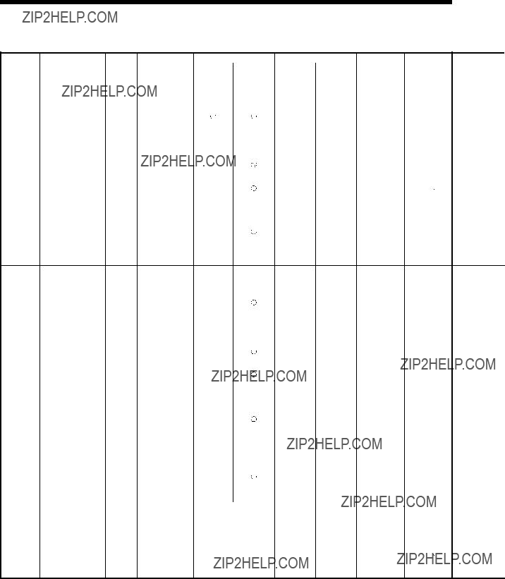
2 MULTIPLE CPU SYSTEM
Table 2.4 Multiple CPU errors which occurs in the Motion CPU (1000 to 10000) (continued)
 OFF (SV13/SV22).
2 - 48

2 MULTIPLE CPU SYSTEM
2 - 49

2 MULTIPLE CPU SYSTEM
2.4.2 Release of
The CPU can perform the release operation for errors only when the errors allow the CPU to continue its operation.
To release the errors, follow the steps shown below.
(1)Eliminate the error cause.
(2)Store the error code to be released in the special register D9060.
(3)Turn the special relay M9060 off to on.
(4)The target error is released.
After the CPU is reset by the release of error, the special relays, special registers and LEDs for the error are returned to the states under which the error occurred.
If the same error occurs again after the release of the error, it will be registered again.
2 - 50

3 COMMON PARAMETERS
3. COMMON PARAMETERS
3.1 System Settings
In the Multiple CPU system, the common system parameters and individual parameters are set for each CPU and written to each CPU.
3 - 1

3 COMMON PARAMETERS
3.1.1 System data settings
Base setting
Multiple CPU Common setting system
parameters
Motion slot setting
Basic system setting
Individual parameters

3 COMMON PARAMETERS
3.1.2Common system parameters
(1)Parameters for operating the Multiple CPU system
In the Multiple CPU system, the common system parameters and individual parameter for each CPU are set and written into each CPU. Regarding the Motion CPU, the items in System Settings related to the entire Multiple CPU system must be identical to the parameter settings in the PLC CPU.
Parameter write
Power supply
Qn(H) Qn(H) Q173H Q172H
CPU CPU CPU CPU
3 - 3
3COMMON PARAMETERS
(2)Parameters common throughout the Multiple CPU system
In the Motion CPU, during initialization the parameters in the table below are verified against the parameters in the PLC CPU of CPU No. 1. Unmatched parameters generate a PARAMETER ERROR (error code: 3012), so the parameters show below must be set identically between Motion CPUs and the PLC CPU of CPU No.1. (If the system settings are changed in a Motion CPU, it is necessary to reset. Therefore, the parameters are checked only during initialization.)
PLC CPUs can use the parameters of the other CPUs via "Multiple CPU parameter utilization" in GX Developer. Since Motion CPUs don't have this function, however, the common parameters must be set for each Motion CPU.
Table of Parameters common throughout the Multiple CPU system
3 - 4

3COMMON PARAMETERS
(a)Multiple CPU settings
Set the following items identically in Multiple CPU Settings (Motion CPU setting) in  P
P
???Number of CPU modules
???Operation mode when a CPU stop error occurred
???Number of automatic refresh points (Settings 1 to 4 must be the same for all CPUs)
???Multiple CPU Settings (Motion CPU setting) in  P
P
Number of CPU modules
Error operation made at the stop of CPU
Number of automatic refresh points
??? Multiple PLC Setting (PLC CPU setting) in GX Developer
3 - 5
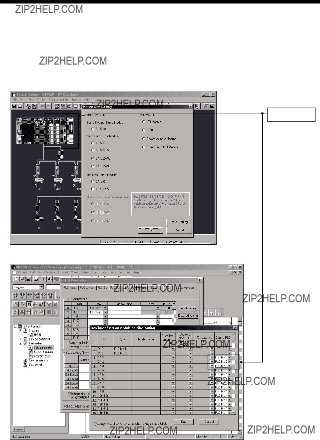
3COMMON PARAMETERS
(b)Motion slot settings
Set the modules controlled by the self CPU by the Motion Slot Settings (Motion CPU setting) in  P.
P.
???Motion Slot Setting (Motion CPU setting) in 
Control CPU No.
??? I/O Assignment Setting (PLC CPU setting) in GX Developer
(Note): Motion slot setting items are different depending on the operating system software.
3 - 6
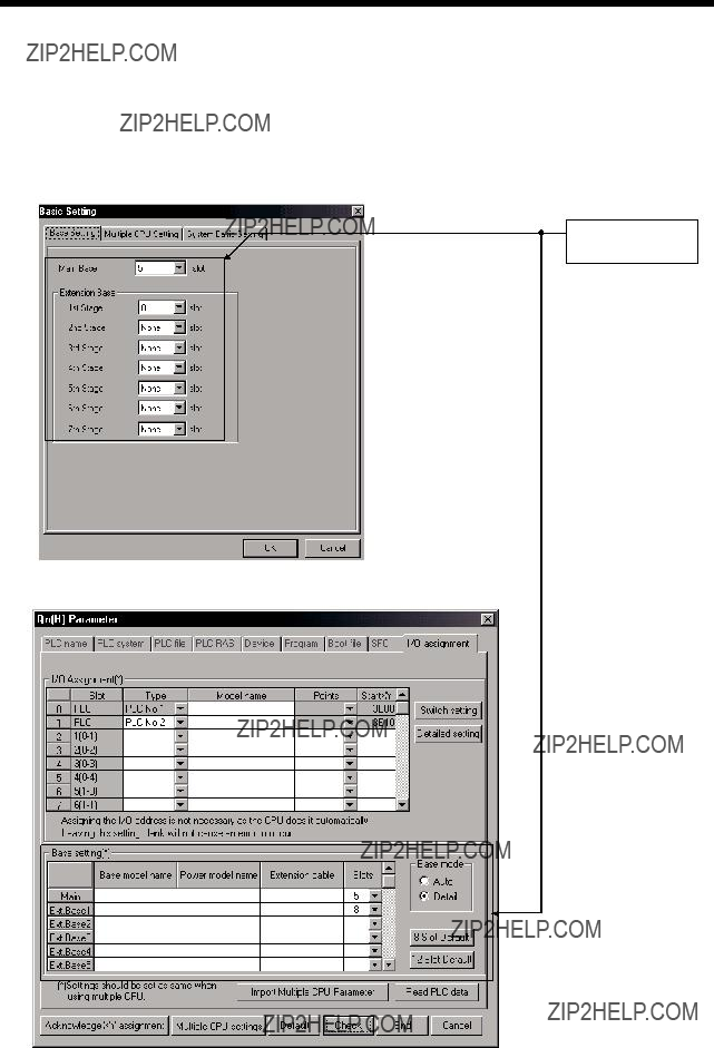
3COMMON PARAMETERS
(c)Base settings
Set the total number of bases and number of slots in each base identically between Base Settings (Motion CPU setting) in  P
P
??? Base Settings (Motion CPU setting) in  P
P
Total number of bases and number of slots in each base
??? I/O Assignment Settings (PLC CPU setting) in GX Developer
(Note) : Only the Motion CPU may be set without setting the PLC CPU.
3 - 7
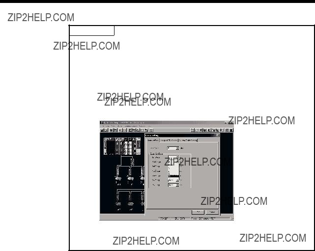
3 COMMON PARAMETERS
POINT
GOT is recognized as an intelligent function modules "16 points 10 slots" on the base (number of extension bases and slot No. are set in the GOT parameter.) for bus connection with GOT.
Set the one extension base (16 points 10 slots) for connection with GOT, then set "10 slots" as number of extension bases for connection with GOT in the system setting (base setting).
<Example>
When the "2nd stage" of extension base is set as connection with GOT. (Set "10" slot as "2nd stage" of extension base in the base setting.)
If the bus connection with GOT is executed without above settings in the base setting of system setting, "SP.UNIT LAY ERROR" (error code: 2124) will occur.
3 - 8

3 COMMON PARAMETERS
3.1.3Individual parameters
(1)Basic system settings
The following explains each item to be set in Basic System Settings.
(a)Operation cycle setting
1)Set the of motion operation cycle (cycles at which a position command is computed and sent to the servo amplifier).
The setting range is 0.4ms/0.8ms/1.7ms/3.5ms/7.1ms/14.2ms/Automatic setting. The actual operation cycle corresponding to 0.4ms is 0.444...ms. Similarly, 0.8ms corresponds to 0.888???ms, 1.7ms to 1.777...ms, 3.5ms to 3.555...ms, 7.1ms to 7.111...ms, and 14.2ms to 14.222???ms, respectively.
2)The default value is "Automatic setting". When "Automatic setting" is selected, the operation cycle is set according to the table below based on the number of axes for servo amplifier set in the System Settings.
3)If the duration of motion operation has exceeded the operation cycle, the operation cycle over flag (M2054) turns ON. Even when "Automatic setting" is selected, the duration of motion operation may exceed the operation cycle depending on the control conditions. The actual duration of motion operation (unit:??s) is stored in the D9188, and the current setting of operation cycle (unit:??s) is stored in the D9197. Monitor these special registers and adjust the set value of operation cycle so that the actual duration of motion operation will not exceed the set operation cycle. (A WDT or other error may occur in the Motion CPU.)
(b)Operation setting upon STOP  RUN
RUN
Set the condition in which the "PLC ready" flag (M2000) turns ON. Select one of the following:
1)M2000 ON upon switching (STOP  RUN) (default)
Condition in which the M2000 turns from OFF to ON
???Change the RUN/STOP switch from the STOP side to the RUN side.
???With the RUN/STOP switch set to the RUN side, turn ON the power or cancel the reset.
3 - 9

3 COMMON PARAMETERS
Condition in which the M2000 turns from ON to OFF
???Change the RUN/STOP switch from the RUN side to the STOP side.
2)M2000 ON upon switching (STOP  RUN) + 1 set in setting register (The M2000 turns ON when the switch is set to the RUN side and 1 is
set in the setting register.)
Condition in which the M2000 turns from OFF to ON
???With the RUN/STOP switch set to the RUN side, set 1 in the setting register for "PLC ready" flag (D704). (The Motion CPU detects a change from 0 to 1 in the lowest bit in the D704).
Condition in which the M2000 turns from ON to OFF
???With the RUN/STOP switch set to the RUN side, set 0 in the setting register for "PLC ready" flag (D704). (The Motion CPU detects a change from 1 to 0 in the lowest bit in the D704).
???Change the RUN/STOP switch from the RUN side to the STOP side.
(c)Forced stop input setting
Specify the bit device used for executing a forced stop in which all servo- amplifier axes are stopped immediately.
Either X (PX) or M can be specified. No default value has been set. The set bit device is designated as contact B and performs the following control in response to ON/OFF of the device.
???Bit device is turned OFF ??? Forced stop input is ON (forced stop)
???Bit device is turned ON ??? Forced stop input is OFF (forced stop is released.)
(d)Latching range setting
Set the following latching ranges for M, B, F, D and W, respectively.
???Range in which the latch can be cleared with the latch clear key (Latch (1))
???Range in which the latch cannot be cleared with the latch clear key (Latch (2))
3 - 10

3COMMON PARAMETERS
(2)Individual module settings
The setting items for each module are shown below.
Setting items for each module
3 - 11

3 COMMON PARAMETERS
Setting items for each module (Continued)
3 - 12

3 COMMON PARAMETERS
(3) External signal input
Servo external signal (Upper stroke limit/Lower stroke limit/Stop signal/Proximity DOG) can be selected for every axis from the following two methods.
(a)Q172LX Servo external signals interface module use
Set the servo external signals interface module, and set axis No. as the "External signal setting" in the system setting.
(b)Servo amplifier input device use
Set "Amplifier input valid" as the external signal input setting in the "Amplifier setting" of system setting.
There are following restrictions to use.
???Count type home position return cannot be used.
???Speed/position switching control cannot be executed.
???Stop signal (STOP) cannot be used.
The correspondence of external signal and input device is shown below.
(Note): Refer to the
Set the external signal setting in the "Input Filter Setting".
Refer to the Programming Manual of the operating system software for the software and correspondence version compatible with the external signal setting.
3 - 13
3COMMON PARAMETERS
(4)System setting errors
Motion CPUs generate a system configuration error under the following conditions:
3 - 14

3 COMMON PARAMETERS
3.2 Assignment of I/O No.
I/O No.s used in the Multiple CPU system include those used by the Motion CPU to communicate with I/O modules/intelligent function modules and those used in the communication between the PLC CPU and the Motion CPU. The following explains each I/O No. and assignment of I/O No..
3.2.1 I/O No. for I/O modules and intelligent function modules
In the Multiple CPU system, the "0H" position(slot) of I/O No. which seen from the PLC CPU is different from the position in the case of a standalone CPU. However, I/O No. of the control module may be assigned independently for each CPU in the Motion CPU.
(1)"0H" position of I/O No.
(a)In the Multiple CPU system, the slots corresponding to the number of units set by a multiple CPU parameter are occupied by the PLC CPU/Motion CPU.
(b)I/O modules and intelligent function modules are installed in slots available to the right of those occupied by the PLC CPU/Motion CPU.
(c)I/O No. of the control module may be assigned independently for each CPU in the Motion CPU. I/O No. of the PLC CPU control modules are assigned sequentially toward the right, starting from "0H" being the I/O module or intelligent function module installed to the immediate right of the slots occupied by the PLC CPU/Motion CPU.
(d)Notation of I/O No.
???Receiving of ON/OFF data by the Motion CPU is deemed input (PX), while outputting of ON/OFF data from the Motion CPU is deemed output (PY).
???I/O No. is expressed in hexadecimal.
(2)Assignment of I/O No. to the Motion CPU control module
Mitsubishi recommends that I/O No. assignment be set as common consecutive No. throughout all CPUs.
However, the I/O No. of the Motion CPUs control input modules, output modules and input/output composite modules may also be set independently of the I/O No. of the PLC CPU control modules.
(The I/O No. of the Motion CPU control modules are indicated with a PX/PY.) The I/O No. of the Motion CPU control modules are invalid during I/O Assignment Settings of the PLC CPU.
I/O assignment
O
U
T
Power supply module
3 - 15

3COMMON PARAMETERS
(3)Setting of the Motion CPU control modules by the PLC CPU
Follow the table below when Motion CPU control modules are set in I/O
Assignment Settings of the PLC CPU. (The PLC CPU handles the Q172LX,
Q172EX and Q173PX as intelligent function modules having 32 occupied points.)
Type and number of points may be left unset.
POINT
(1)Set the I/O device of the Motion CPU within the range from PX/PY000 to PX/PYFFF. Set the number of real I/O points within 256 points. (I/O No. may not be consecutive.)
(2)As for the Motion CPU, the Q172LX, Q172EX, Q173PX and QI60 are not included in the number of real I/O points.
3 - 16

3 COMMON PARAMETERS
3.2.2 I/O No. of PLC CPU and Q173HCPU/Q172HCPU
In the Multiple CPU system, I/O No. is assigned to the PLC CPU/Motion CPU to enable communication between the PLC CPU and Motion CPU using the following instructions:
???The Multiple CPU dedicated instructions
???The Motion CPU dedicated instructions
???The Multiple CPU communication dedicated instructions
The I/O No. of the PLC CPU/Motion CPU are fixed based on the installed slots and cannot be changed.
The table below lists the I/O No. of the PLC CPU/Motion CPU installed in the CPU base unit of the Multiple CPU system.
The I/O No. of the PLC CPU/Motion CPU are used in the following cases:
???When writing data to the shared CPU memory of the self CPU using the S. TO instruction.
???When reading data from the shared CPU memory of the other CPU using the FROM instruction.
???When reading data from the shared CPU memory of the other CPU using an intelligent function module device (U \G
\G )
)
???When reading device data directly from the Motion CPU from the PLC CPU using the "S(P).DDRD" instruction.
???When writing device data directly to the Motion CPU from the PLC CPU using the "S(P).DDWR" instruction.
REMARK
???Refer to Section "2.3 Communication between the PLC CPU and the Motion CPU in the Multiple CPU System" for communication between the PLC CPU and the Motion CPU.
3 - 17
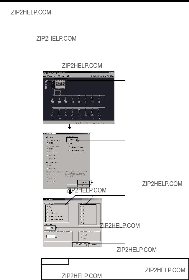
3 COMMON PARAMETERS
3.2.3 Setting I/O No.
The procedure for the I/O No. setting for the Motion CPU in System Settings of  P
P
Refer to the help of  P
P
<System Settings>
1)
<Motion Slot Settings>
2) Select the I/O module.
5) Set the first I/O No. (PX No., PY No.).
6) Click [OK].
(Note): Display of system setting and motion slot setting are different depending on the operating system software.
POINT
I/O No.s cannot be assigned automatically, unlike a PLC CPU for which I/O No. are assigned automatically if such setting is omitted in the Motion CPU. In the Motion CPU, be sure to set the first I/O No. in System Settings for each module used.
3 - 18

3 COMMON PARAMETERS
3.3Servo Parameters
(1)The servo parameters control the data fixed by the specifications of the servo amplifier and servomotor controlled in the parameter set for each axis and the control of the servomotor.
(2)The servo parameters are set by the Setup software (MR Configurator).
3.3.1 Servo parameters of servo amplifier
The servo parameters to be set are shown in Tables 3.1 to 3.4.
Refer to the "Servo amplifier Instruction Manual" for details of the servo parameters.
Instruction Manual list is shown below.
Refer to the help for handling of the Setup software (MR Configurator).
???Set the presence/absence of absolute position detection system.
3 - 19

3 COMMON PARAMETERS
Table 3.1 Servo parameter (Basic setting parameters) list (Continued)
3 - 20

3 COMMON PARAMETERS
Table 3.1 Servo parameter (Basic setting parameters) list (Continued)
???Set the encoder pulses
???Select the number of output pulses per
???The number of
POINTS
(1)When the items marked " " in the above table has changed, make the Multiple CPU system reset or power supply OFF to ON. And, once turn OFF the servo amplifier power supply and then turn ON it again.
3 - 21

3COMMON PARAMETERS
(2)Gain/filter parameters
Table 3.2 Servo parameter (Gain/filter parameters) list
3 - 22

3 COMMON PARAMETERS
Table 3.2 Servo parameter (Gain/filter parameters) list (Continued)
3 - 23
3 COMMON PARAMETERS
Table 3.2 Servo parameter (Gain/filter parameters) list (Continued)
3 - 24

3 COMMON PARAMETERS
Table 3.2 Servo parameter (Gain/filter parameters) list (Continued)
3 - 25

3 COMMON PARAMETERS
Table 3.2 Servo parameter (Gain/filter parameters) list (Continued)
POINTS
(1)When the items marked " " in the above table has changed, make the Multiple CPU system reset or power supply OFF to ON. And, once turn OFF the servo amplifier power supply and then turn ON it again.
3 - 26

3 COMMON PARAMETERS
(3) Extension setting parameters
Table 3.3 Servo parameter (Extension setting parameters) list
3 - 27

3 COMMON PARAMETERS
Table 3.3 Servo parameter (Extension setting parameters) list (Continued)
0: Invalid
1: Valid
(When alarm history clear is made valid, the
PC21 BPS Alarm history clear ??? Clear the alarm history.3.3.24 alarm history is cleared at next
the alarm history is cleared, the setting is automatically made invalid (reset to 0).)
POINTS
(1)When the items marked " " in the above table has changed, make the Multiple CPU system reset or power supply OFF to ON. And, once turn OFF the servo amplifier power supply and then turn ON it again.
3 - 28

3COMMON PARAMETERS
(4)I/O Setting Parameters
Table 3.4 Servo parameter (I/O Setting Parameters) list
3 - 29

3 COMMON PARAMETERS
Table 3.4 Servo parameter (I/O Setting Parameters) list (Continued)
POINTS
(1)When the items marked " " in the above table has changed, make the Multiple CPU system reset or power supply OFF to ON. And, once turn OFF the servo amplifier power supply and then turn ON it again.
3 - 30

3 COMMON PARAMETERS
3.3.2 Regenerative brake option
This parameter is set to use the regenerative brake option.
0 0
 Selection of regenerative brake option
00 : Regenerative brake option is not used.
 EMR-J3-10B:
 EMR-J3-20B
 ESupplied regenerative brake resistors or regenerative brake option is used with the
01 :  FR-RC(-H)
 FR-CV(-H)
02 :
03 :
04 :
05 :
06 :
08 :
09 :
FA : When regenerative brake resistors or regenerative brake option supplied to
3.3.3 Absolute position detection system
This parameter is set to use the absolute (absolute position) system in the position control mode.
0:Invalid (Used in incremental system)
1:Valid (Used in absolute system)
3.3.4Function selection
This parameter is set to use the forced stop input of servo amplifier.
 Selection of servo forced stop
0:Valid (Forced stop (EM1) is used.)
1:Invalid (Forced stop (EM1) is not used.)
When not using the forced stop of servo amplifier, set the selection of servo forced stop to "1: Invalid".
The forced stop automatically turns on inside the servo amplifier.
3.3.5 Auto tuning mode
This parameter is used to select the gain adjustment mode.
3 - 31

3 COMMON PARAMETERS
3.3.6Auto tuning response
(1)This parameter is used to increase the response of servo amplifier. The response of servo amplifier increases by changing (as 1, 2, ??? 5) the setting value of auto tuning response.
(2)It is increased in order from the low response setting side while checking the vibration and stop setting time immediately before stopping motor or machine. If a machine resonance will occur at this time, decrease the setting value.
(3)Change the auto tuning response setting while stopping motor.
3.3.7
(1)
(2)If an
Amount of droop
Setting value for
 t
t
(M2402+20n)
OFF
(3) Setting range is 0 to 50000[PLS].
3 - 32

3 COMMON PARAMETERS
3.3.8 Rotation direction selection
This parameter is used to set the rotation direction at load side of the servomotor.
3.3.9 Encoder output pulse
This parameter is used to set the encoder pulses
"PC03: Encoder output pulse selection" can be used to select the output pulse setting or output division ratio setting. The number of
(1)For output pulse designation
Set "0000h" (initial value) to "PC03: Encoder output pulse selection". Set the number of pulses per servomotor revolution.
Output pulse  Setting value [PLS/rev]
For example, set "5600h" to "PA15: Encoder output pulse", the actually output
(2) For output division ratio setting
Set "001 h" (initial value) to "PC03: Encoder output pulse selection".
The number of pulses per servomotor revolution is divided by the setting value.
Output pulse = Resolution per servomotor revolution [PLS/rev]
Setting value
For example, set "8h" to "PA15: Encoder output pulse", the actually output A/B- phase pulses are shown below:
3 - 33
3 COMMON PARAMETERS
3.3.10 Adaptive tuning mode
3.3.11 Vibration suppression control tuning mode
This parameter is used to set the vibration suppression control tuning mode.
3.3.12 Feed forward gain
This parameter is used to improve the trackability in response of servo amplifier.
Setting range is 0 to 100[%]. (Servo amplifier use)
3.3.13 Notch shape selection 1
This parameter is used to select the machine resonance suppression filter 1 (Notch shape selection 1).
3 - 34

3 COMMON PARAMETERS
3.3.14 Notch shape selection 2
This parameter is used to select the machine resonance suppression filter 2 (Notch shape selection 2).
0
 Machine resonance suppression filter 2 selection
1:Invalid
2:Valid
3.3.15 Low pass filter selection
This parameter is used to select the low pass filter.
 Low pass filter selection
0:Automatic setting
1:Manual setting (Setting value of "PB18: Low pass filter setting")
3.3.16Slight vibration suppression control selection
This parameter is used to select the slight vibration suppression control and
0 0
 Slight vibration suppression control selection
0:Invalid
1:Valid
3: PI control is always valid
3 - 35
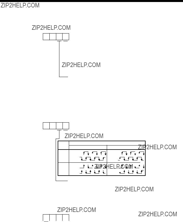
3 COMMON PARAMETERS
3.3.17 Gain changing selection
This parameter is used to select the gain changing condition.
0 0
 Gain changing selection
Under any of the following conditions, the gains change based on the setting value of servo parameter PB29 to PB32.
0:Invalid
1:Control instructions from Motion CPU
2:Command frequency (Setting value of "PB27: Gain changing condition")
3:Droop pulse value (Setting value of "PB27: Gain changing condition")
4:Servomotor speed (Setting value of "PB27: Gain changing condition")
Gain changing condition
0: Valid at more than condition
(For control instructions from Motion CPU, valid with gain changing command ON) 1: Valid at less than condition
(For control instructions from Motion CPU, valid with gain changing command OFF)
3.3.18 Encoder output pulse selection
This parameter is used to select the encoder output pulse direction and encoder pulse output setting.
0 0
 Encoder pulse output phase changing
Changing the phases of a,
Encoder output pulse setting selection
0:Output pulse designation
1:Division ratio setting
3.3.19 Function selection
This parameter is used to select the serial encoder cable.
0 0 0
 Serial encoder cable communication system selection
0:
1:
The following serial encoder cables are
The other all serial encoder cables are
Incorrect setting will result in an encoder error 1 (Error code: 2016) or
encoder error 2 (Error code: 2020).
3 - 36

3 COMMON PARAMETERS
3.3.20 Function selection
This parameter is used to select the
0 0 0

0:Valid
1:Invalid
If
It can be checked the Motion SFC program (SV13/SV22)/Motion program (SV43) of Multiple CPU system without connecting a motor.
POINT
Function selection
3.3.21 Analog monitor 1 output
This parameter is used to output the operating status of servo amplifier to analog monitor in real time. The operating status can be checked by anaolg output. This function is used to monitor the status of servo amplifier using an ammeter or synchronize the torque/speed with the other servo amplifiers.
Set the signal provided to the analog monitor 1 output.
0 0 0
 Analog monitor 1 output
0Servomotor speed (??8V/max. speed)
1Torque (??8V/max. torque)
2Servomotor speed (+8V/max. speed)
3Torque (+8V/max. torque)
4Current command (??8V/max. current command)
5Speed command (??8V/max. speed command)
6Droop pulses (??10V/1 102[PLS])
7Droop pulses (??10V/1 103[PLS])
8Droop pulses (??10V/1 104[PLS])
9Droop pulses (??10V/1 105[PLS])
AFeedback position (??10V/1 106[PLS])
BFeedback position (??10V/1 107[PLS])
CFeedback position (??10V/1 108[PLS])
DBus voltage (??8V/400V)
3 - 37

3 COMMON PARAMETERS
3.3.22 Analog monitor 2 output
This parameter is used to output the operating status of servo amplifier to analog monitor in real time. The operating status can be checked by anaolg output. This function is used to monitor the status of servo amplifier using an ammeter or synchronize the torque/speed with the other servo amplifiers.
Set the signal provided to the analog monitor 1 output.
0 0 0
 Analog monitor 2 output
0Servomotor speed (??8V/max. speed)
1Torque (??8V/max. torque)
2Servomotor speed (+8V/max. speed)
3Torque (+8V/max. torque)
4Current command (??8V/max. current command)
5Speed command (??8V/max. speed command)
6Droop pulses (??10V/1 102[PLS])
7Droop pulses (??10V/1 103[PLS])
8Droop pulses (??10V/1 104[PLS])
9Droop pulses (??10V/1 105[PLS])
AFeedback position (??10V/1 106[PLS])
BFeedback position (??10V/1 107[PLS])
CFeedback position (??10V/1 108[PLS])
DBus voltage (??8V/400V)
3.3.23 Function Selection
This parameter is used to set the home position setting condition.
It is set when using the absolute position encoder.
0 0 0
 Selection of home position setting condition
0:Need to pass motor Z phase after the power supply is switched on.
1:Not need to pass motor Z phase after the power supply is switched on.
3.3.24 Alarm history clear
This parameter is used to clear the alarm history.
0 0 0
 Alarm history clear
0:Invalid
1:Valid
When alarm history clear is made valid, the alarm history is cleared at
next
3 - 38

3 COMMON PARAMETERS
3.3.25 Output signal device selection 1
This parameter is used to set the signal output to the connector
0 0 0
 Select the output device of the
The devices that can be assigned in each control mode are shown below.
If any other device is set, it is invalid.
(Note): Encoder pulse unit For manufacturer setting. Never change this setting.
3.3.26 Output signal device selection 2
This parameter is used to set the signal output to the connector
3.3.27 Output signal device selection 3
This parameter is used to set the signal output to the connector
3 - 39

3 COMMON PARAMETERS
3.3.28 Function selection
This parameter is used to set the ALM output signal at warning occurrence.
3 - 40
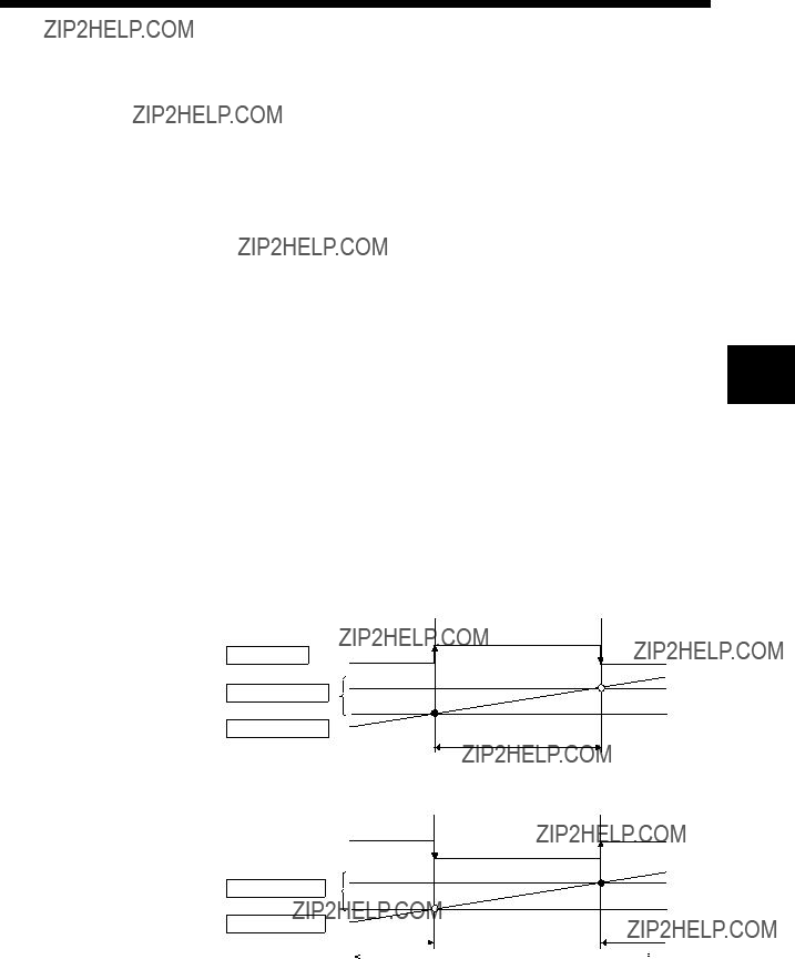
4 AUXILIARY AND APPLIED FUNCTIONS
4. AUXILIARY AND APPLIED FUNCTIONS
4.1 Limit Switch Output Function
This function is used to output the ON/OFF signal corresponding to the data range of the watch data set per output device.
Motion control data or optional word data can be used as watch data. (Refer to Section "4.1.2 Limit output setting data" for details.) A maximum output device for 32 points can be set regardless of the number of axes.
4.1.1 Operations
(1) ON output to an output device is made while the watch data value is in the ON output region set with (ON Value) and (OFF Value) in this function.
(a) (ON Value), (OFF Value) and watch data value are handled as signed data.
ON output region where an ON output is made to the output device is4 governed by the magnitude relationship between (ON Value) and (OFF
Value) as indicated below.
1) (ON Value) < (OFF Value)
Output device
ON region setting
Watch data value
(ON Value) (Watch data value)
 (OFF Value)
2) (ON Value) > (OFF Value)
ON Value
ON region setting
OFF Value
Watch data value
4 - 1

4 AUXILIARY AND APPLIED FUNCTIONS
3) (ON Value) = (OFF Value)
Output device
ON region setting
Watch data value
OFF in whole region
ON Value OFF Value
(b)The limit switch outputs are controlled based on the each watch data during the PCPU ready status (M9074: ON) by the PLC ready flag (M2000) from OFF to ON.
When the PCPU ready flag (M9074) turns OFF by turning the PLC ready flag (M2000) from ON to OFF, all points turn OFF. When (ON Value) and (OFF Value) are specified with word devices, the word device contents are input to the internal area when the PLC ready flag (M2000) turns from OFF to ON. After that, the word device contents are input per motion operation cycle, and limit switch outputs are controlled.
(c)Multiple outputs (Up to 32 points) can be also set to one watch data. In each setting, the output device may be the same.
If multiple ON region settings have been made to the same output device, the logical add of the output results in the regions is output.
Output device
ON region setting No.2 

ON region setting No.1
OFF Value
ON Value
OFF Value
ON Value
Watch data value
(2)Output enable/disable bit can be set and executed enable/disable of the limit switch outputs
Limit switch output control is executed when the output enable/disable bit is ON, and the output is OFF when it is OFF.
If there is no setting, the outputs are always enabled.
(3)Forced output bit can be set and turned the forcibly output of the limit switch outputs
The output is ON when the forced output bit is ON. Priority is given to control of this setting over off (disable) of the "output enable/disable bit".
If there is no setting, no forced outputs are not always made.
4 - 2
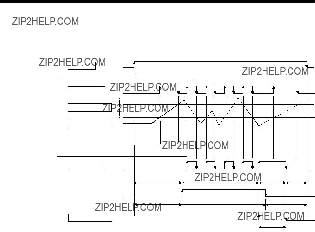
4AUXILIARY AND APPLIED FUNCTIONS
(4)When the multiple watch data, ON region, output enable/disable bit and forced output bit are set to the same output device, the logical add of output results of the settings is output.
4 - 3
4 AUXILIARY AND APPLIED FUNCTIONS
4.1.2 Limit output setting data
Limit output data list are shown below.
Up to 32 points of output devices can be set.
(The following items of No.1 to No.5 are set together as one point.)
(1)Output device
(a)Set the bit device which outputs the ON/OFF signal toward the preset watch data.
(b)As the output device, the following devices can be used.
Be careful because it affect a positioning operation, when the positioning dedicated devices are set.
4 - 4

4AUXILIARY AND APPLIED FUNCTIONS
(2)Watch data
(a)This data is used to perform the limit switch output function. This data is comparison data to output the ON/OFF signal. The output device is
(b)As the watch data, motion control data or optional word device data can be used.
1)Motion control data
a)SV13/SV22
b) SV43
2) Word device data
4 - 5

4AUXILIARY AND APPLIED FUNCTIONS
3)When the optional device data is set, the following data type is set as the data type to be compared.
(3)ON region setting
(a)The data range which makes the output device turn ON/OFF toward the watch data.
(b)The following devices can be used as the ON Value and OFF Value of the data range.
The data type of device/constant to be set is the same as the type of watch data.
(4)Output enable/disable bit
(a)Set the status of output enable/disable bit when the limit switch output is forbidden during operation.
1)The following control is exercised.
(b) Usable devices
4 - 6

4AUXILIARY AND APPLIED FUNCTIONS
(5)Forced output bit
(a)Set the "forced output bit" when you want to forcibly provide the limit switch outputs during operation.
1)The following control is exercised.
(b) Usable devices
4 - 7

4 AUXILIARY AND APPLIED FUNCTIONS
4.2 Absolute Position System
The positioning control for absolute position system can be performed using the
If the machine position is set at the system starting, home position return is not necessary because the absolute position is detected at the power on.
The machine position is set with the home position return using the Motion SFC program (SV13/SV22)/Motion program (SV43) or a peripheral device.
(1)Conditions of the absolute position system start
Perform a home position return after machine adjustment at the absolute position system start.
(2)In the absolute positioning system, the absolute position may be lost in the following cases:
Set the absolute position with a home position return.
(a)The battery unit is removed or replaced.
(b)The battery error of the servo amplifier occurs. (It is detected at the servo amplifier power on).
(c)The machine system is disturbed by a shock.
(d)The cable between servo amplifier and encoder is removed, or the servo amplifier or encoder is replaced.
(3)The current value history can be monitored using of the "System setting mode- allowable travel during power off" or "Monitor mode" using a peripheral device. (Refer to the help of  P
P
 CAUTION
 After removing or replacing the battery unit, correctly install the new unit and set the absolute position.
 After a servo battery error occurs, eliminate the cause of the error and ensure operation is safe before setting the absolute position.
 After the mechanical system is disturbed by a shock, make the necessary checks and repairs, and ensure operation is safe before setting the absolute position.
4 - 8

4 AUXILIARY AND APPLIED FUNCTIONS
POINT
(1)The address setting range of absolute position system is 2147483648 to 2147483647.
It is not possible to restore position commands that exceed this limit, or current values after a power interruption.
Correspond by the [degree] setting for an infinite feed operation.
(2)Even when the current value address is changed by a current value change instruction, the restored data for the current value after a power interruption is the value based on the status prior to execution of the current value change instruction.
(3)When home position return has not been completed (home position return request is ON), restoration of the current value after a power interruption is not possible.
4 - 9

4 AUXILIARY AND APPLIED FUNCTIONS
4.2.1 Current value control
The current value when using the ABS encoder is controlled by following functions.
(1)The validity of an encoder data during operation is checked.
(a)Checks that the amount of change of the encoder in a 3.5[ms] is within 180 degrees at the motor axis. (An error is displayed at the abnormal.)
(b)Checks that adjustment of the encoder data and
(2)The following values can be monitored by the current value history using the peripheral devices.
(a)Current value history monitor Month/day/hour/minute
The time such as at the completion of home position return and servo amplifier power supply ON/OFF is indicated.
In order to indicate the time correctly, turn on M9028 (clock data read request) in the Motion SFC program (SV13/SV22)/Motion program (SV43) after setting the clock data of special register.
(b)Encoder current value
When using the  B,
B,
(Note) : For the encoder current value in the home position data area, the encoder current value when the motor is within the
(c) Servo command value
The command value issued to the servo amplifier is indicated.
(d) Monitor current value
The current value controlled in the Motion CPU is indicated.
(Note) : A value near the feed current value/machine value is indicated. However, because the monitor current value and feed current value/machine value are different data, it is not abnormal even if a different value is indicated.
(e) Alarms
When an error for current value restoration occurs at the servo amplifier power on, an error code is indicated.
(3)By setting of the "Allowable travel during power off", if the encoder data changes exceeding the setting range during
"Allowable travel during power off" cannot be set for the Linear servo amplifier.
4 - 10

4 AUXILIARY AND APPLIED FUNCTIONS
4.3
This function is used to store the specified positioning data in the specified device (D, W). The signal from input module controlled in the Motion CPU is used as a trigger. It can be set in the system setting of  P.
P.
(1)Positioning data that can be set
(a)SV13/SV22
(b) SV43
(2) Modules and signals to be used
(Note) : Only one PLC input module can be used.
4 - 11

4 AUXILIARY AND APPLIED FUNCTIONS
4.4 ROM Operation Function
This function is used to store beforehand the user programs and parameters in the internal FLASH ROM memory
4.4.1 About the ROM operation function
The outline procedure of ROM operation function is shown below.
(1)Turn on or reset the power supply of Multiple CPU system in the "Mode operated by RAM".
(2)Execute a trial run and adjustment by creating the system setting, programs and parameters using  P.
P.
(3)Turn on or reset the power supply of Multiple CPU system in the "Installation mode ??? mode written in ROM".
(4)Write the system setting, programs and parameters of SRAM  P.
P.
(5)Start a normal operation by starting the Motion CPU in the "Mode operated by ROM" after reading the system setting, programs and parameters written in the internal FLASH ROM to the internal SRAM.
POINT
(1)Switch the operation mode using a DIP switches of Motion CPU module.
(2)Confirm the operation mode with "Mode LED" and "BOOT LED" of Motion CPU module.
Outline of processing is shown next page.
4 - 12


4 AUXILIARY AND APPLIED FUNCTIONS
4 - 16

4 AUXILIARY AND APPLIED FUNCTIONS
4.4.3ROM operation function details
(1)Operation mode
"Operation mode" of CPU is set by the state of DIP switch 2, 3, 5 of Motion CPU module at the power supply on or reset of Multiple CPU system.
DIP switch setting, operation mode and operation mode overview are shown below.
(a) DIP switch setting and operation mode
4 - 17

4 AUXILIARY AND APPLIED FUNCTIONS
POINT
Do not change the DIP switch setting during operation.
Be sure to turn off the power supply of the Multiple CPU system to change the DIP switch setting.
(2)Applicable data into ROM
The data contents batch written to the internal FLASH ROM by ROM writing are shown below. Backup data except the followings (current position of servomotor in absolute position system, home position and latch device, etc.) cannot be written to the internal FLASH ROM.
(a)Content of applicable data into ROM
4 - 18
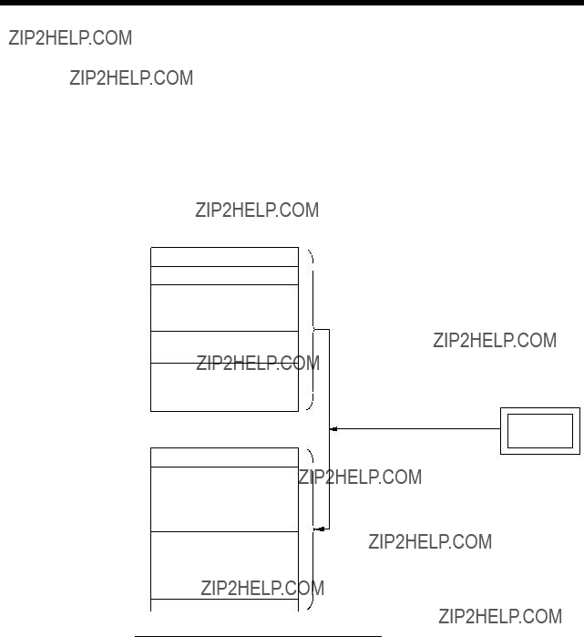
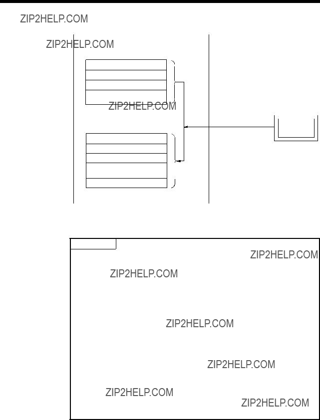

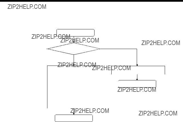

4 AUXILIARY AND APPLIED FUNCTIONS
4.4.4 Operating procedure of "ROM writing"
The operating procedure of ROM writing using the  P
P
(1) SV13/SV22
 System setting screen
Operating procedure
1) Display "ROM/RAM" communication dialog screen after clicking on "Communication" - "Transfer" of the system setting menu screen. (Note) : Select "Transfer" at the ROM writing.
4) Select "Write" of "When selecting the ROM" screen. (Note) : ALL data are
writing.
Not select these items.
Mechanical system program and cam data cannot be written to the ROM when using the
The above items are not displayed on the window.
POINT
Be sure to write the all data beforehand to the RAM of
Motion CPU at the ROM writing.
4 - 23

4 AUXILIARY AND APPLIED FUNCTIONS
4.5 Security Function
This function is used to protect the user data of Motion CPU by registering a password. The following user data can be protected in this function.
"Write Protection" or "Read/Write Protection" can be set every user data.
4.5.1 Password registration/change
There are two following methods to register/change a password.
???[Communication]  [Password]
  [Register/Change]
???Password [Register/Change] key of the communication setting screen displayed by "[Communication]  [Transfer]".
<SV13/SV22>
<SV43>
4 - 25


4 AUXILIARY AND APPLIED FUNCTIONS
4.5.2 Password clearance
There are two following methods to delete a password.
???[Communication]  [Password]
  [Delete]
???Password [Delete] key of the communication setting screen displayed by "[Communication]  [Transfer]".
<SV13/SV22>
<SV43>
(1)Procedure for password clearance
(a)The password data set in the Motion CPU are displayed.
(b)Enter old password in the password column, and push [Execute] key.
(c)A password set in the Motion CPU will be deleted by success of password check. (A blank is displayed in the registration column.)
POINT
(1)When a password is deleted, the password data in the project is also deleted. Be sure to save a password.
(2)When an operation is stopped while a clearance of password by reset or power OFF of Motion CPU, the data may not be deleted. In this case, delete a password again to restore the user data.
4 - 27

4 AUXILIARY AND APPLIED FUNCTIONS
4.5.3 Password check
When the user data program set in a password is corrected, the password check screen is displayed automatically.
<SV13/SV22>
<SV43>
(1)Procedure for password check
(a)Enter old password in the password column, and push [Execute] key.
(b)A password protection set in the Motion CPU will be released temporarily by success of password check, and the user data program can be corrected.
(c)A password is memorized until  P
P
POINT
A password memorized by success of password check is valid even if the project change is executed while  P
P
4 - 28

4 AUXILIARY AND APPLIED FUNCTIONS
4.5.4 Password save
There are two following methods to save a password in the project data.
???Registration/change or clearance password
???A password read with user data by [Transfer]  [Read].
A password saved in the project data can be registered with user data, when the user data are written in the Motion CPU that does not set password by [Transfer]  [Write].
The updated password data is saved in the project data by the following operations.
???Password [Save] key of communication setting screen displayed by "[Communication]  [Transfer]".
???Password [Save] key of password registration/change/clearance screen.
???When the password registration/change/clearance screen ends, if there is
(1)A password and registration conditions for each operation
The password data in the project is not saved in the project before password save.
POINT
Save a password after delete of password to delete the password data in the project. Or, create new project and divert user data from the project with password data to create the project without password data.
4 - 29
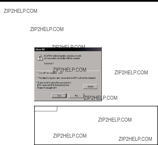
4 AUXILIARY AND APPLIED FUNCTIONS
4.6 Clear All
This function is used to clear the all user data, password setting, and backup area in Motion CPU.
Clear all can be executed in the following operation.
???Select "[Option]  [Clear All]" of the communication screen displayed by "[Communication]
  [Transfer]".
POINT
(1)Turn off the PLC ready flag (M2000) and test mode ON flag (M9075) to execute "Clear All".
(2)Turn off the power supply of servo amplifier.
(3)All user data and password setting are cleared at the "Clear All". Backup of user data and password setting data is recommended before clearance.
4 - 30

4 AUXILIARY AND APPLIED FUNCTIONS
4.7 Communication via Network
The communication between the personal computer and the Motion CPU is possible via Q series Network module (MELSECNET/10(H), Ethernet,
Refer to the following manuals for the specifications of each network modules of MELSECNET/10(H), Ethernet,
(1) MELSECNET/10(H) module :
???QCPU User's Manual(Hardware Design, Maintenance and Inspection)
???Q Corresponding MELSECNET/H Network System Reference Manual(PLC to PLC network)
???Q Corresponding MELSECNET/H Network System Reference Manual(Remote I/O network)
(2)Ethernet interface module : QJ71E71,
???Q Corresponding Ethernet Interface Module User's Manual(Hardware)
???Q Corresponding Ethernet Interface Module User's Manual(Basic)
???Q Corresponding Ethernet Interface Module User's Manual(Application)
???Q Corresponding Ethernet Interface Module User's Manual(Web function)
???Q Corresponding MELSEC Communication Protocol Reference Manual
(3)
???QJ61BT11 Control & Communication Link System Master/Local Module User's Manual (Hardware)
???GX
???
(4)Serial communication module : QJ71C24,
???Serial Communication Module User's Manual(Hardware)
???Q Corresponding Serial Communication Module User's Manual(Basic)
???Q Corresponding Serial Communication Module User's Manual(Application)
???Q Corresponding MELSEC Communication Protocol Reference Manual
4 - 31
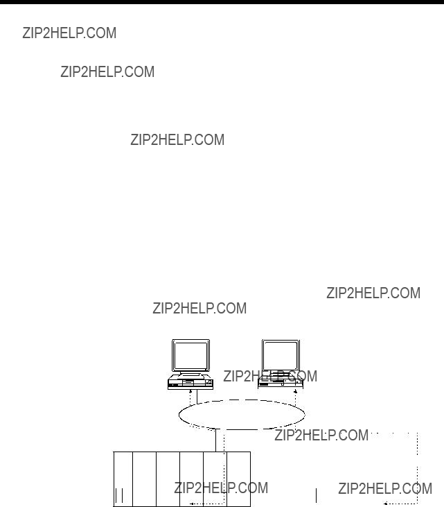

4 AUXILIARY AND APPLIED FUNCTIONS
4.7.2Access range of the communications via network
(1)Network configuration via the MELSECNET/10(H) or the Ethernet
(a)It can access the other CPU via the network from the programming software (GX Developer,  P,
P,
(b)It can access the other CPU via the network from the programming software in the personal computer by connecting the personal computer equipped with Ethernet to MELSECNET/10(H) or Ethernet board to the Ethernet to MELSECNET/10(H) or Ethernet.
(c)The access range of above (1) and (2) can be accessed to 8 network points by setting the routing parameter to the control CPU of the network module and the CPU which connected the personal computer.
4 - 33
4AUXILIARY AND APPLIED FUNCTIONS
(2)Network configuration via the
(a)It can access the other CPU via the  P,
P,
(b)It can access the other CPU via the
(c)The access range of above (1) is only the CPU on the
(d)The access range of above (2) is only the CPU of the connected the CC- Link.
 : Communication is possible
: Communication is possible (Setting of the routing parameter is necessary.)
 : Communication is impossible
4 - 35
4AUXILIARY AND APPLIED FUNCTIONS
(3)Network configuration via the RS422/485
(a)It can access the other CPU via the  P,
P,
(b)The access range of above (1) is only the CPU on the
 : Communication is possible
: Communication is possible (Setting of the routing parameter is necessary.)
 : Communication is impossible
4 - 36


4 AUXILIARY AND APPLIED FUNCTIONS
 : Communication is possible
: Communication is possible (Setting of the routing parameter is necessary.)
 : Communication is impossible
4 - 38

4 AUXILIARY AND APPLIED FUNCTIONS
4.8Monitor Function of the Main Cycle
(1)Information for main cycle of the Motion CPU processing (process cycle executed at free time except for motion control) is stored to the special register.
(2)Since the automatic refresh of shared CPU memory and normal task of Motion SFC program (SV13/SV22)/Motion program (SV43) are executed in the main cycle, make it reference for process time, etc. to program.
(3)There are following methods to shorten a main cycle.
(a)Lengthen an operation cycle setting.
(b)Reduce the number of event task programs to execute in the Motion SFC program. (SV13/SV22)
(c)Reduce the number of normal task programs to execute simultaneously in the Motion SFC program. (SV13/SV22)
(d)Reduce the number of automatic refresh points of shared CPU memory. (SV43)
(4)When a main cycle is lengthened (more than 1.6[s]), a WDT error may occur in the Motion CPU.
(5)Details of main cycle monitor register is shown below.
4 - 39

4 AUXILIARY AND APPLIED FUNCTIONS
4.9Servo Parameter Reading Function
(1)When the servo parameters are changed, the Motion CPU will be automatically read the servo parameters and reflected them to the servo parameter storage area in the Motion CPU. Therefore, an operation to read servo parameters is unnecessary in the following cases.
(a)The parameters are changed by auto tuning.
(b)The parameters are changed by connecting directly MR Configurator to the servo amplifier.
POINT
If the power supply of Motion CPU is turned off/reset or the power supply of servo amplifier is turned off immediately after change, it may not be reflected.
(2)After executing the servo parameter reading function, when it needs to reflect the servo parameters changed to the  P,
P,
4 - 40

4 AUXILIARY AND APPLIED FUNCTIONS
4.10 Optional Data Monitor Function
This function is used to store the data (refer to following table) up to three points per axis to the specified devices (D, W, #) and monitor them.
POINT
(1)The updating cycle of data is every operation cycle.
(2)Set an even number as device setting in the two word data.
4 - 41

4 AUXILIARY AND APPLIED FUNCTIONS
4.11 Connect/Disconnect Function
This function is used to connect/disconnect the SSCNET communication temporarily, when the servo amplifier or SSCNET cable on the SSCNET system are exchanged during the power supply ON of Motion CPU. An user side requires connect/disconnect to a system, and a system side stores the states of command accept waiting or execute waiting for connect/disconnect. Moreover, also use this device to
(1) Setting value/monitor value of connect/disconnect device are shown below

4AUXILIARY AND APPLIED FUNCTIONS
(2)Procedure for connect/disconnect function to exchange the servo amplifier or SSCNET cable are shown below.
(a)Operation procedure to disconnect
1)Set the axis No. of servo amplifier to disconnect in D9112. (1 to 32)
2)Check that D9112 is
(Disconnect execute waiting)
3)Set
4)Check that D9112 is "0: Disconnect command accept waiting". (Completion of disconnection)
5)After checking the LED display "AA" of servo amplifier to be disconnected, turn the power supply of servo amplifier OFF.
(b)Operation procedure to
1)Turn the power supply of servo amplifier ON.
2)Set
3)Check that D9112 is
4)Set
5)Check that D9112 is "0:
6)After checking the servo ready (M2415+20n) of servo amplifier to re- connect, resume operation of servo amplifier.
POINT
(1)After completion of SSCNET communication disconnect processing, check the LED display of servo amplifier is "AA",and then turn the power supply of servo amplifier OFF.
(2)When the power supply for axis 1 is turned OFF/ON on the SSCNET system, a connect/disconnect processing is unnecessary.
(3)If the power supply of servo amplifier connected after axis 2 of SSCNET system is turned OFF, operation failure may occur in the other axes. Be sure to use a disconnect function to turn OFF the power supply of servo amplifier.
4 - 43
4AUXILIARY AND APPLIED FUNCTIONS
(3)Flow of device value for connect/disconnect operation are shown below.
(a)Disconnect operation
(b)
POINT
When the power supply of
4 - 44
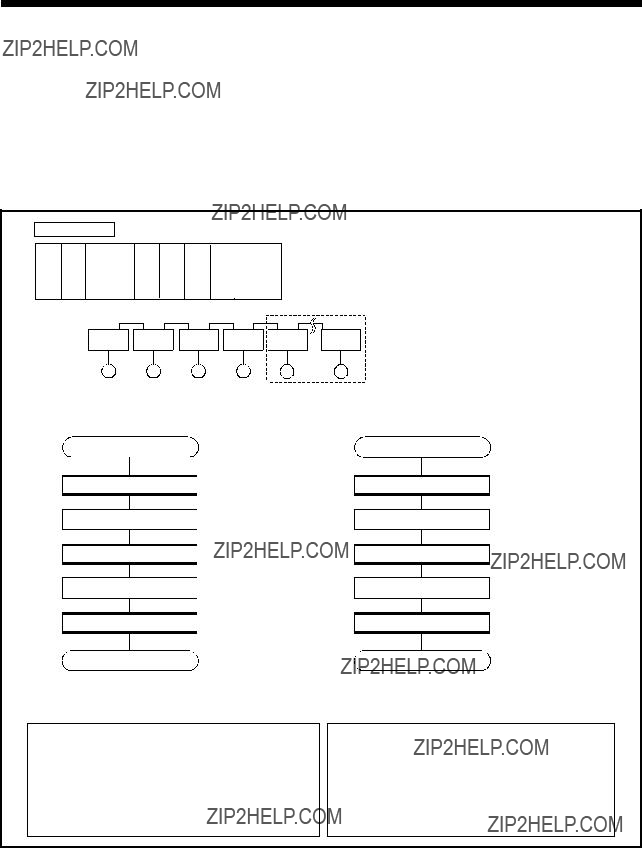
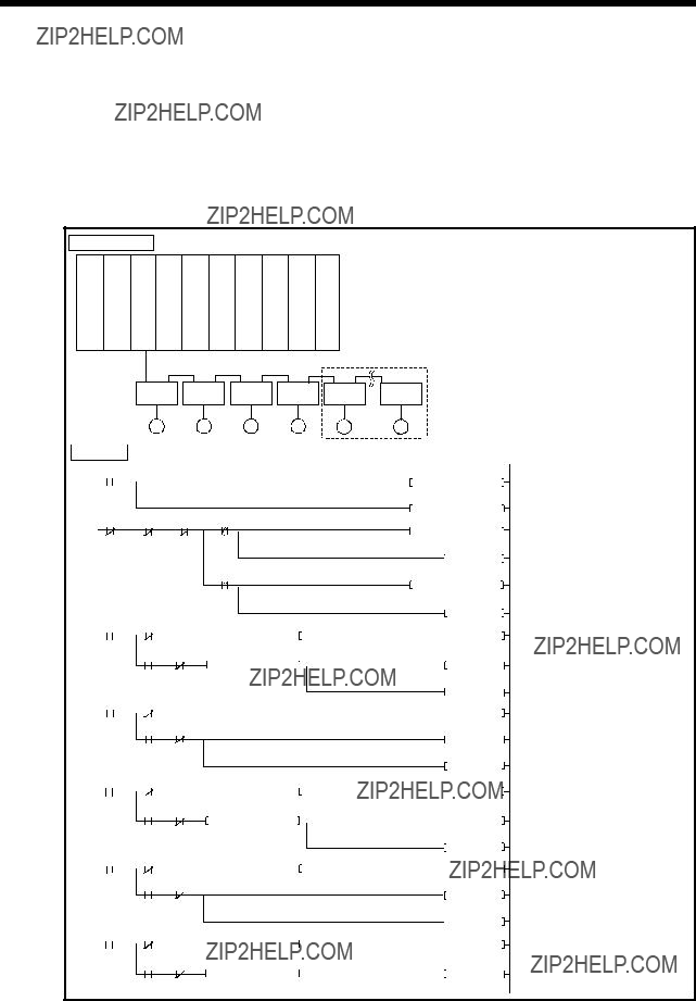

4 AUXILIARY AND APPLIED FUNCTIONS
MEMO
4 - 47
WARRANTY
Please confirm the following product warranty details before using this product.
1. Gratis Warranty Term and Gratis Warranty Range
If any faults or defects (hereinafter "Failure") found to be the responsibility of Mitsubishi occurs during use of the product within the gratis warranty term, the product shall be repaired at no cost via the sales representative or Mitsubishi Service Company.
However, if repairs are required onsite at domestic or overseas location, expenses to send an engineer will be solely at the customer's discretion. Mitsubishi shall not be held responsible for any
[Gratis Warranty Term]
Note that an installation period of less than one year after installation in your company or your customer???s premises or a period of less than 18 months (counted from the date of production) after shipment from our company, whichever is shorter, is selected.
[Gratis Warranty Range]
(1)Diagnosis of failure
As a general rule, diagnosis of failure is done on site by the customer.
However, Mitsubishi or Mitsubishi service network can perform this service for an agreed upon fee upon the customer???s request.
There will be no charges if the cause of the breakdown is found to be the fault of Mitsubishi.
(2)Breakdown repairs
There will be a charge for breakdown repairs, exchange replacements and on site visits for the following four conditions, otherwise there will be a charge.
1)Breakdowns due to improper storage, handling, careless accident, software or hardware design by the customer
2)Breakdowns due to modifications of the product without the consent of the manufacturer
3)Breakdowns resulting from using the product outside the specified specifications of the product
4)Breakdowns that are outside the terms of warranty
Since the above services are limited to Japan, diagnosis of failures, etc. are not performed abroad.
If you desire the after service abroad, please register with Mitsubishi. For details, consult us in advance.
2. Exclusion of Loss in Opportunity and Secondary Loss from Warranty Liability
Mitsubishi will not be held liable for damage caused by factors found not to be the cause of Mitsubishi; opportunity loss or lost profits caused by faults in the Mitsubishi products; damage, secondary damage, accident compensation caused by special factors unpredictable by Mitsubishi; damages to products other than Mitsubishi products; and to other duties.
3. Onerous Repair Term after Discontinuation of Production
Mitsubishi shall accept onerous product repairs for seven years after production of the product is discontinued.
4. Delivery Term
In regard to the standard product, Mitsubishi shall deliver the standard product without application settings or adjustments to the customer and Mitsubishi is not liable for on site adjustment or test run of the product.
5.Precautions for Choosing the Products
(1)These products have been manufactured as a
(2)Before using the products for special purposes such as nuclear power, electric power, aerospace, medicine, passenger movement vehicles or under water relays, contact Mitsubishi.
(3)These products have been manufactured under strict quality control. However, when installing the product where major accidents or losses could occur if the product fails, install appropriate backup or failsafe functions in the system.
(4)When exporting any of the products or related technologies described in this catalogue, you must obtain an export license if it is subject to Japanese Export Control Law.

 Installation mode
  mode written in ROM
 Installation mode
 mode written in ROM Motion CPU module
 HCPU-T
 ERR.
ERR. M.RUN
M.RUN BAT.
BAT.


 P,
P, P,
P, P.
P. mode written in ROM (Install the operating system software.)
 mode written in
 mode written in ROM" as a DIP switch 5 of the Motion CPU module.
 P.
P. P,
P, mode written in ROM" as a DIP switch 5.
 System setting data
 Parameter for servo control
 Servo program (SV13/SV22)
 Motion SFC parameter (SV13/SV22)
 Motion SFC program (SV13/SV22)
 Mechanical system program (SV22)
 Cam data (SV22)
 Motion parameter (SV43)
  Motion program (SV43)
 After that, it is same operation at the RAM operation.
 After that, it cannot be operated because of stop status.
 "Mode operated by ROM" after confirm the contents for programs and parameters of internal SRAM.
 System setting screen
 P.
P.
 : Communication is possible
 : Communication is impossible
 P,
P, CPU (C24)
  Network
  Link
Link  CPU
CPU CPU (C24)
  Link
Link  Network
  CPU
CPU Network
  Link
Link  CPU
CPU Link
Link  Network
  CPU
CPU CPU (C24)
  Network
  Link
Link  Network
  CPU
CPU CPU (C24)
  Link
Link  Network
  Link
Link  CPU
CPU Network
  Link
Link  Network
  CPU
CPU Link
Link  Network
  Link
Link  CPU
CPU : Usable
  : Unusable
 : Communication is possible
 : Communication is impossible