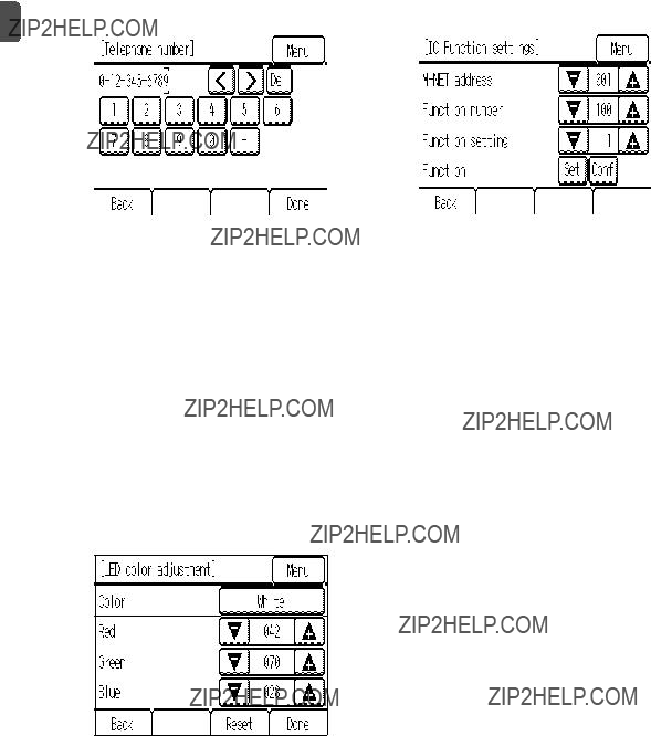
(2)Setup screen
(a)Group setting
Use this screen to register the indoor units and the AHC to be controlled from the controller. 1Select an indoor unit or an AHC address in the
[Address] field.
The number of units that can be registered.
Indoor unit: 16 units maximum
AHC: 1 unit maximum
*AHC cannot be controlled from the controller unless indoor units are registered with the system.
2Touch the [Set] button to register the address, and [Del] to delete the address.
???Successful address registration/deletion:
The registered address(es) will appear on the left side of the screen.
Deleted address will not appear on the screen.
???Error:
"Request denied." or "Is not to be connected" will appear.
(b) Interlocked LOSSNAY
Use this function to interlock the operation of indoor units and LOSSNAY units. 1To register LOSSNAY units
Select the indoor unit address in the Add. 1 section. Select the interlocked LOSSNAY address in the Add. 2 section. Touch the [Set] button to save the setting.
2To search for an interlocked setting
Touch the [Conf] button to display in the left column the addresses of the units that are interlocked with the unit whose address was set in the Add. 1 section.
3To delete the interlock settings
After taking Step 2 above, select the address to be deleted in the Add. 2 section, and then touch the [Del] button.
When the setting or deletion is successfully completed, ???Completed??? will appear below [Function] field on the screen.
If setting or deletion fails, ???Request denied??? will appear below [Function] field on the screen.
(c) Search connection information
Use this screen to specify a unit and search for the controllers that are connected to the unit. 1Select an address in the [Address] field.
2Touch the [Conf] button to search for the interlocked units.
The results will appear in the left column. (When multiple units are found, the addresses that do not fit on the first page will appear on the successive pages.)
???Search error:
"Request denied." will appear.
After completing the settings, touch the [Back] button on the [Setup] screen. The message ???Collecting the information from the air conditioner.??? will appear, and then the screen will jump to the HOME screen. This signals the completion of the setup process.
Access the Service Menu from the HOME screen to make the settings for other items as necessary.
 1 Safety Precautions


 WARNING
 CAUTION
 WARNING
 CAUTION
 WARNING
 CAUTION
 WARNING
 CAUTION
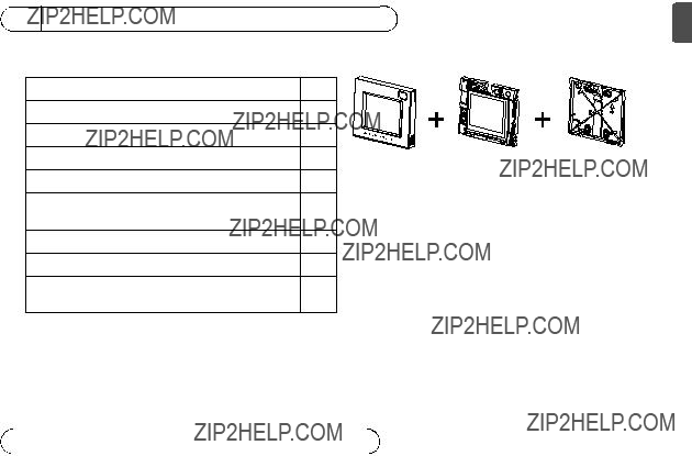

 4 System diagram
 CAUTION block.
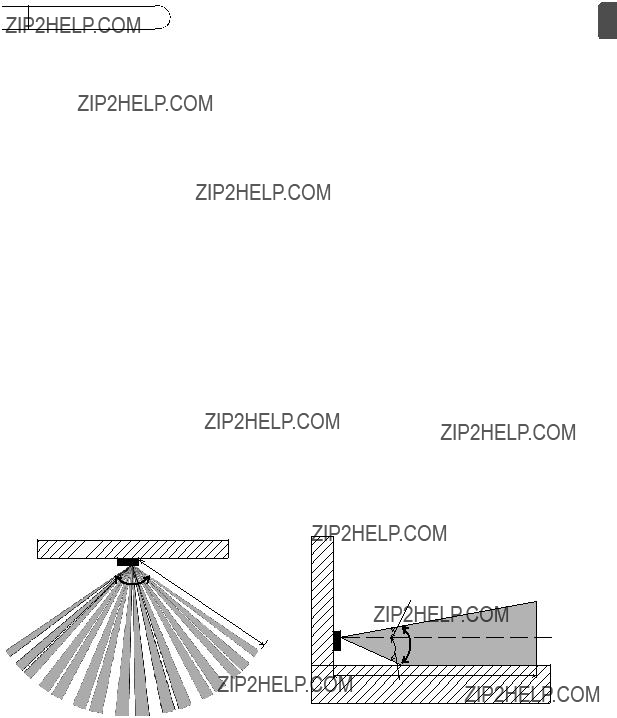
 5 How To Install
 : Detection area

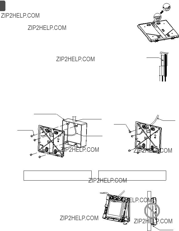
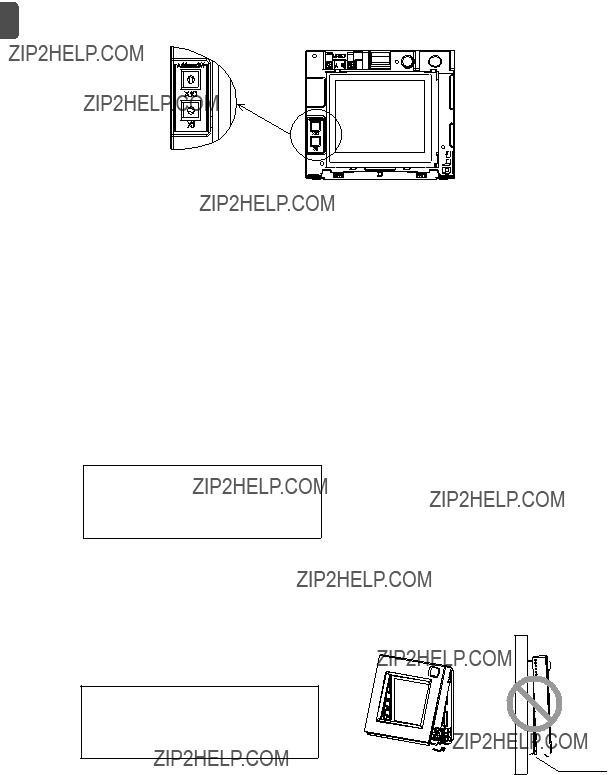


 Should not
 be lifted
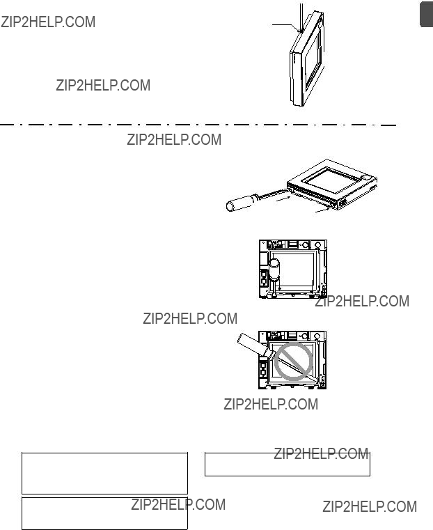

 Lightly push the tip in.
 6 Important
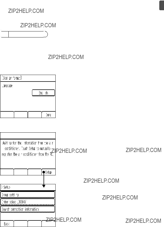
 1 Initial Settings
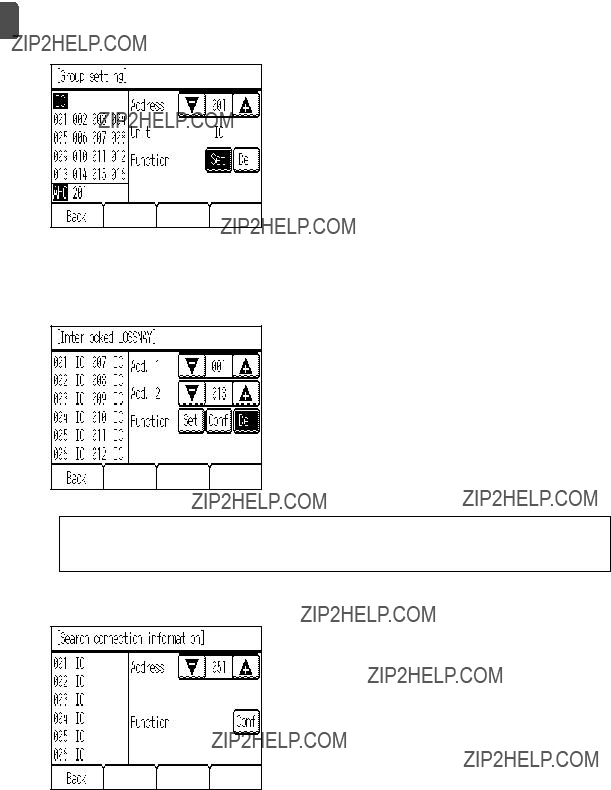
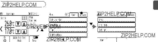
 2 Service Menu