Dolphin StorExpress DSE4XM1 DSE4XM2
User Guide for Windows
Revision Information: Revision 0.3
Dolphin Interconnect Solutions
www.dolphinics.com
Dolphin StorExpress DSE4XM1 DSE4XM2
User Guide for Windows
Revision Information: Revision 0.3
Dolphin Interconnect Solutions
www.dolphinics.com

March 2009
Dolphin Interconnect Solutions believes the information in this publication is correct; however, the information is subject to change without notice.
Dolphin Interconnect Solutions does not claim that the use of its products in the manner described in this publi- cation will not infringe on any existing or future patent rights, nor do the descriptions contained in this publica- tion imply the granting of licenses to make, use, or sell equipment or software in accordance with the description.
???Dolphin Interconnect Solutions. 2009. All rights reserved. Printed in U.S.A.

1
Introduction
Congratulations on your purchase of a Dolphin StorExpress product. This guide pro- vides user instructions for the following StorExpress models:
???DSE4XM1
???DSE4XM2
These products are part of the DSE4XM family of StorExpress products.
Dolphin???s StorExpress is a PCI Express based solid state storage system designed to deliver superior response times and storage capacity. Providing large capacity and fast direct storage, StorExpress connects directly to any PCI Express system. It is the ideal solution for deploying fast solid state cache solutions to improve the performance of database or
Offering both superior power utilization and outstanding performance, this fl ash based solution signifi cantly lowers annual power usage while delivering outstanding perfor- mance. StorExpress leverages the latest solid state SLC NAND technology to provide extremely faststorage solutions that outperform traditional disk based systems.
1.1 System Requirements
The DSE4XM requires an open x4 or x8 PCI Express slot for each DXH510 Host Adapter card.
Please refer to Chapter 3 for supported operating systems.
1.2 DSE4XM Components
Your DSE4XM product includes the following items:
???DSE4XM chassis

???DXH510 PCI Express host adapter card
???DXH510
???2 - 1m CX4 cables
???StorExpress USB Key, containing
???DSE4XM User???s Guide for Windows
???DSE4XM User???s Guide for Linux
???ioManager User???s Guide
???Quick Start Instructions
???Configuration Sheet
1.3Features and Performance
The DSE4XM product has the following features:
???480 Gbyte or 960 Gbyte NAND Flash SLC using
???Performance for x4, x8 and dual x8 server connection(s), respectively:
???800 MB/s, 1500 MB/s, and 2700 MB/s (read)
???600 MB/s, 1250 MB/s, and 2500 MB/s (write)
???80,000, 150,000, and 270,000 I/O operations per second (IOPS)1
???< 50 microseconds read access latency2
???Server connection options
???x4 PCI Express for up to four servers
???x4 or x8 PCI Express for up to two servers
???x4, x8, or dual x8 PCI Express for one server
???Requires PCI Express slot in server (two slots for dual x8 connection)
???Additional DXH510 host adapter required for each server connection or dual x8 connection
???Supports external
???Extended distance up to 100 meters
1.Based on 4KB packet sizes
2.Based on 4KB packet sizes
1.4 Specifications
1.4.1 Mechanical
The following specifications are for the DSE4XM chassis:
???Standard 4U rackmount chassis
???Dimensions
???Height: 6.96??? (4U /176.8mm)
???Depth: 18.9 (480mm)
???Width: 19??? (483mm)
???Weight approximately 32lbs (14.5kg)
1.4.2Environmental
???Operating Temperature: 00C to 500C ambient
???Storage Temperature:
???Relative Humidity:
1.4.3Electrical
???Operating
???Power Supply: 300 watt dual PSU
1.4.4Agency Approvals
???FCC Part 15, Class A
???EMC Directive CE Mark, EN55022, EN55024,
???VCCI, Class A
1.5 Customer Support
If you continue to have issues with your system or need service, please contact Dolphin customer support at http://www.dolphinics.com/support

2
Hardware Installation
This chapter describes how to install your DSE4XM hardware.
Your DSE4XM includes a DXH510 PCI Express host adapter card and two
The DSE4XM supports additional configurations accommodating connections to up to four servers, with a fixed amount of storage allocated to each server. Each additional server requires a DXH510 adapter card and cable to connect to the DSE4XM chassis. Allocation of memory to each server is specified at the time the product is ordered and
2.1 DSE4XM Chassis Overview
Figure

Figure
Table
Figure

Figure
Caution: For protection of the StorExpress devices, we recommend that you do not attempt to service or remove the cover of your DSE4XM chassis. However, if you do, power should be disconnected from the chassis prior to servicing the chassis or removing the cover for any reason. In order to disconnect power remove the power cord from its receptacle in the back of the chassis as shown in Figure
2.2 Installing DXH510 Card in Server
The DXH510 host adapter card is shown in Figure
Figure
Caution: Electrostatic discharge (ESD) can damage electronic components. Be sure that you are properly grounded prior to any hardware installation procedure using an ESD protection device such as a wrist strap.
If you are installing the DXH510 in a
1.Locate the serial number on the back of your DXH510 and record it for future refer- ence.
2.Power off the server and disconnect the power cable.
3.Remove the server's access panel. Locate an available PCIe slot.
???Consult your server's documentation for details on removing the panel and identifying PCIe slots.
Note: Your DXH510 is designed for use in a x8 PCIe slot. It will work in a x16 slot, but this does not improve performance. Your DXH510 can also work in a x2 or x4 slot but performance may be diminished in a x2 slot, or in a x4 slot if a x8 connection is intended.
4.Follow server manufacturer???s instructions for installing PCIe
5.Replace the server???s access panel
6.Plug in the server???s power cable
You have completed the hardware installation of the DXH510 into the server. If you are connecting multiple servers to the DSE4XM chassis, repeat this process for each server. Each server requires a DXH510 host adapter to connect to the DSE4XM chassis. If you are making a dual x8 connection to a single server, locate a second PCI Express slot and install the second DXH510 adapter.
2.2.1
For installation in a
Caution: Electrostatic discharge (ESD) can damage electronic components. Be sure that you are properly grounded prior to any hardware installation procedure using an ESD protection device such as a wrist strap.
1.Locate the
2.Remove the four screws, indicated in Figure
3.Remove the bracket carefully from the device.
4.Align the connectors on the DXH510 with the openings in the
5.Adjust the bracket so that the notches on the bracket tabs fit around the guides on the back of the card. The bracket guides are illustrated in Figure
6.Attach the
7.Return to Step 2 of Section 2.2.

Figure
2.3 Connecting the DXH510 to Chassis
A server connects to the DSE4XM chassis using the DXH510 PCI Express host adapter card. One or two cables are used to connect the DXH510 to the DSE4XM chassis. One cable provides a x4 (8 Gbps) connection; two cables provide a x8 (16 Gbps) connection.
Two
Table
The DSE4XM chassis has two pairs of connectors (four total), which are used to cable to the DXH510 host adapter. As shown in Figure
One set of connectors can be used for a x8 connection when cabled to a single DXH510, or for two x4 connections when each connector in the set is cabled to a different DXH510 adapter card. Two sets of two connectors allow for connection to up to four DXH510 adapter cards in this manner.
Each DXH510 card has one pair of connectors, as shown in Figure
Table
??? Only required if a x8 connection is desired. May be left unconnected if a x4 connection only is needed.
The single server dual x8 configuration is similar to the two server configuration, however in this case both DXH510:1 and DXH510:2 adapters reside in the same server.
Attach the cable(s) to the required connectors for your configuration as specified by Table

Figure
Figure
Figure
Note: Cables should be strain relieved or strapped to a cabinet/rack to ensure additional reliability.
Note: Cables should be connected according to the configuration of your DSE4XM product. The configuration is documented on the configuration sheet included with your product. The standard StorExpress configuration is single server. Multiple server configurations require additional DXH510 adapter cards and cables, which may be purchased through http://www.dolphinics.com.
2.4Powering up the DSE4XM
1.Connect main power
Auxiliary power is supplied to the DSE4XM when AC power is connected.
2.An AC power switch for each power supply unit is located on the back of the chas- sis near the power connector, as shown in Figure
3.A DC power switch is provided in the front of the chassis, as shown in Figure
The DSE4XM chassis provides automatic remote
???When fully powered, the DSE4XM will go through a self test. You will observe that for 0.5 seconds the P0 and P1 LEDs on the Uplink slots will turn green. Then for 0.5 seconds, the P0 and P1 LEDs turn yellow. If the servers connected to the DSE4XM are powered down, or if the connectors are not cabled, then the LEDs will turn off.
4.
???Chassis fans will turn on
???The Uplink Slot P0 and P1 LEDs will transition from yellow to off and then green for connected ports, as described in the previous step.
5.Check the P0 and P1 LEDs for both the DXH510 and the DSE4XM Uplink slot(s)
???For a x8 or a single x4 connection, the P0 LED should be illuminated
???For two x4 connections, both the P0 and P1 LEDs should be illuminated
6.Follow the procedure outlined in Chapter 3 for driver software installation. If you are prompted by the operating system for a driver, click Cancel.
7.Repeat the
Note: If you are running a Windows operating system, Dolphin provides drivers to support the DXH510. These drivers are available on the Dolphin website at www.dolphinics.com/ support
2.5 Troubleshooting
Table

3
Software User Guide
3.1 Software Installation
This section describes how to install software for your DSE4XM product. The DSE4XM storage device is the
3.1.1 New ioDrive Installation
To install the ioDrive software on a new system:
1.Make sure you have completed the DSE4XM hardware installation steps in Chapter 2.
2.If you want to use SNMP with your ioDrive, review Section 3.6 for details on that part of the installation.
3.Login in as Administrator or have Administrator rights.
4.Download the ioDrive Windows Setup Program from http://www.dolphinics.com/ support to your desktop or a convenient directory.
5.Run the Setup program.
6.Follow the onscreen prompts to complete the install. (If Setup requests you to ver- ify the driver install, click Yes to continue.)
The Setup program will:
???Create a Program
???Create shortcuts to the utilities and documentation in this folder.
???Install and load the ioDrive Windows driver.
???Install the ioManager administrator console.
???Create an ioManager desktop icon.
It will also create shortcuts in the All
???User documentation
???ioManager and ioManager Remote
???SNMP License Readme file
When Setup creates the
???
???
???
???
???
???
7.Proceed to the appropriate section to continue:
???Section 3.1.3 Outdated Firmware Check on Windows XP Pro or Windows 2003 Server
???Section 3.1.4 Outdated Firmware Check on Windows Vista or Windows Server 2008
3.1.2Existing ioDrive Installation
To install the latest ioDrive Windows software on an existing installation:
1.Review the Release Notes and the Errata file available for this version of the soft- ware for additional steps that may be needed to complete the install.
2.If you want to use SNMP with your ioDrive, review Section 3.6 for details on that part of the installation.
3.Login as Administrator (or have administrator rights).
4.Uninstall the existing
5.Download the ioDrive Windows Setup Program from http://www.dolphinics.com/ support to your desktop or a convenient directory.
6.Run the Setup program.
7.Follow the onscreen prompts to complete the install. (If Setup requests you to ver- ify the driver install, click Yes to continue.)
8.Click Restart once the Setup program finishes.
9.Once the system reboots, proceed to the appropriate section to continue:
???Section 3.1.3 Outdated Firmware Check on Windows XP Pro or Windows 2003 Server
???Section 3.1.4 Outdated Firmware Check on Windows Vista or Windows Server 2008
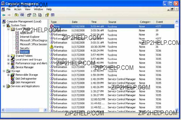
3.1.3 Outdated Firmware Check on Windows XP Pro or Windows 2003 Server
After installing the ioDrive software, check the Windows System Event Log for fiodrive entries. These entries will show details of the ioDrive driver status.
To view the Windows System Event Log:
1.Choose Start > Control Panel
2.Click on Administrative Tools.
3.Click on Event Viewer.
4.Click on System in the console tree. The System Event Log appears in the dialog.
5.Click on the Source column to resort the list by source.
6.Scroll through the list to identify any fiodrive Error entries:.
7.
Check to see if the fiodrive Error entry says ???ioDrive (x) firmware is too old???. (The x is the PCI bus number of the ioDrive you just installed.)
If there is a fiodrive error entry warning of old firmware, follow the instructions in the Section 3.2.4.3 later in this guide to update the firmware.
If the System Event Log shows no fiodrive error entries (as in the example above), then your ioDrive is ready to receive a Windows file system.
If you choose to enable SNMP support, continue to Section 3.6.
3.1.4 Outdated Firmware Check on Windows Vista or Windows Server 2008
After installing the ioDrive software, check the Windows System Event Log for fiodrive entries. These entries will show details of the ioDrive driver status.
To view the Windows System Event Log:
1.Click Start.
2.Type event viewer in the Search box.
3.Press Enter to launch the Event Viewer.
4.Click Windows Logs in the console tree.
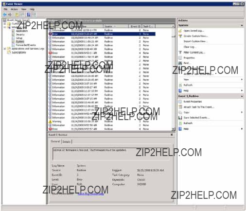
5. Select System in the console tree. The System Event Log appears in the dialog.
6.Click the Source column to
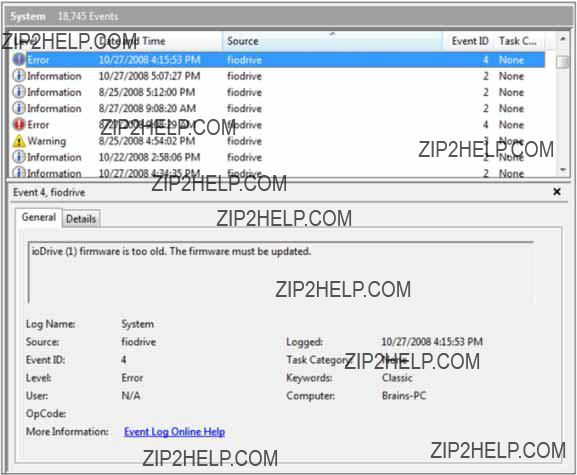
7.Scroll through the list to identify any fiodrive error entries.
8.Highlight an entry in the list to view its details.
Check to see if there is a fiodrive Error entry that reads ???ioDrive (x) firmware is too old???. (The x is the number of the ioDrive you just installed.)

If there is a fiodrive error entry warning of old firmware, as in the example above, follow the instructions in the Section 3.2.4.3 later in this guide to update the firmware.
If the System Event Log shows no fiodrive error entries, then your ioDrive is ready to receive a Windows file system.
If you choose to enable SNMP support, refer to Section 3.6.
3.1.5 ioDrive Naming
The ioDrive receives a name and number as part of the install process for identification. The syntax is fctx where x is the number of the PCIe bus where you installed the ioDrive. Use ioManager to view this bus number or you can:
1.Choose Start > Control Panel > System > Hardware > Device Manager.
2.Select
3.Click on your ioDrive in the list. The Properties dialog appears.
The Location field shows the PCIe bus number for your device (fct13 in this case):
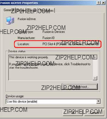
Note: The system manufacturer assigns bus numbers, which can range from 0 on up. These numbers may or may not reflect the physical location of the bus. For example, the second slot from the edge of the motherboard may be Bus 2, but it could also be Bus 16 or another arbitrary number. Checking Device Manager is one way to confirm the specific bus number for your installation. You can also use ioManager to view this number.)
3.1.6 Adding a File System to the ioDrive
With the ioDrive and driver installed, you can now use the Windows Disk Management utility to make your device available to applications. Typically, Windows will detect the new device, initialize it and display it in Disk Management. You can then add partitions, format a volume, or create a RAID configuration on your ioDrive using the standard Windows procedures (see the Windows Disk Management Utility documentation for more details)
If Windows does not, you may need to initialize it manually. To initialize an ioDrive:
1.Select Start > Control Panel.
2.Click Administrative Tools.
3.Click Computer Management.
4.Click Disk Management in the Storage section of the console tree.

5.Locate and
6.Click Initialize Disk.
You can now use the Disk Management Utility to add a file system to your ioDrive.
3.1.7 Creating a RAID Configuration
You can use your ioDrive as part of a RAID configuration. To do so, you must format your ioDrive as a dynamic volume. In turn, you can then use this dynamic volume to create
Note: Windows XP Professional does not support software RAID or mirroring. It does support spanning and striping.
For specific steps to perform a RAID configuration, see the Windows Disk Management Utility documentation for details.
Note: If you are using RAID1/Mirroring, and one device fails, be sure to run a fio- format on the replacement device (not the remaining good device) before rebuilding the RAID.
3.2 ioDrive Maintenance
The ioDrive includes both software utilities for maintaining the device as well as external LED indicators to display its status.
3.2.1 ioDrive LED Indicators
Each ioDrive slot includes three LEDs showing drive activity or error conditions. The LEDs for one slot is shown in Figure
Figure
Table
* Later versions of the ioDrive use an
3.2.2 The ioManager Console
Your ioDrive software includes the ioManager console application. This GUI performs the most common operations you need to do with the ioDrive. In addition, it provides a detailed information screen on each of your installed devices.
The ioManager can perform:
???Firmware upgrades
???
???Attach and detach actions
The ioManager installs as part of your Windows Setup process. Details on how to use ioManager appear in the ioManager User Guide available in the All Programs/Fusion- io/ioManager menu.
3.2.3 ioDrive Command Line Utilities
The Windows Setup package also includes five command line utilities for managing your ioDrive. They include:
???
???
???
???
???
Each of these utilities is described in detail in Section 3.5.
3.2.4 Common Maintenance Tasks
The most common tasks involve drivers and firmware.
3.2.4.1 Uninstalling the ioDrive Windows Driver
To uninstall the ioDrive Windows driver:
1.Go to Start > Control Panel.
2.Click Administrative Tools.
3.Click Computer Management.
4.Click Device Manager in the console tree at the left.
5.Expand the
6.
7.Click Uninstall.
Windows will uninstall the driver.
3.2.4.2 Upgrading the ioDrive Windows Driver
To upgrade the ioDrive Windows driver:
1.Refer to the Release Notes and the Errata file for this new version of the driver for details on any additional steps to perform the upgrade.
2.Follow the steps above to uninstall the existing driver.
3.Download the latest driver from http://www.dolphinics.com/support.
4.Either unzip or run the Windows package to copy the files to a convenient direc- tory.
5.Go to Start > Control Panel.
6.Click Administrative Tools.
7.Click Computer Management.
8.Click Device Manager in the console tree at the left.
9.Expand the
10.
11.Click Update Driver Software. Refer to Section 3.4 for details on the remaining steps to install the updated driver.
The operating system will now detect your ioDrive.
Note: Read both the release notes and the errata files that come with each new release as well as these installation instructions to ensure no loss of data when performing upgrades.

3.2.4.3 Upgrading the ioDrive Firmware
Caution: You should upgrade the firmware only if the System Event Log reports
3.2.4.3.1 Viewing the Firmware Version
You can view the ioDrive???s firmware version using the Windows System Event Log. You can then use this information to evaluate upgrading to a newer firmware release.
To view the firmware version in the System Event Log:
1.Choose Start > Administrative Tools.
2.Click Event Viewer.
3.Click System in the console tree at the left. The System Event Log appears in the dialog.
4.Click the Source column to
5.Scroll through the list to identify any fiodrive entries.
6.Highlight each entry for fiodrive that is of the ???Information??? type and view its details. Each installed ioDrive will have an entry listing its firmware version.
Record this firmware version information for future reference.
3.2.4.3.2 Performing the Upgrade
Warning: It is extremely important that the power not be turned off to either the server or the DSE4XM chassis during a firmware upgrade, nor should the cable be disconnected. Power or connectivity loss during a firmware upgrade could cause device failure. Consider adding a UPS to the system prior to performing a firmware upgrade to prevent this from happening.
Caution: You should back up the data on the ioDrive prior to any upgrade as a precaution.
Note: You must upgrade the ioDrive driver if you upgrade the device firmware.
Note: To correctly perform the firmware upgrade, you must power the system, including the DSE4XM chassis, all the way down and bring it all the way back up. This shutdown and restart is required for the upgrade to complete on the ioDrive.
Note: A firmware upgrade may in some instances require a
Note: Upgrading the firmware may take several minutes. The update command displays a progress bar to indicate the pace of the upgrade.
Typically, you use the ioManager console to perform firmware upgrades. You can also perform the upgrade using the
To upgrade the firmware on the ioDrive using
1.Open a Command Prompt. Navigate to the Program
2.Run the Detach command for your device at the Command Prompt. For example:
detaches the ioDrive labeled ???fct0???. You need to specify the name of your drive you want to detach. (Each ioDrive is labeled /dev/fct# where # is its PCIe bus number. Use
The
3.Type the following command at the Command Prompt:
where <path> is the location of the ioDrive firmware. The default path is Program
Note: All three of the ioDrive slot LED indicators will light during the update pro- cess.
4.Completely power down the server and the DSE4XM chassis. Turn off the AC power to the DSE4XM chassis, and turn it back on again. Restart the server, which
will completely power up the DSE4XM chassis, to complete the firmware upgrade. (It must be a power down and restart of both the server and the chassis to ensure a complete reset of the+ system and the ioDrive(s). If there are multiple servers con- nected to the DSE4XM chassis, these servers should be powered down as well, and powered back up after the DSE4XM is powered up.)
3.2.5 Unmanaged Shutdown Issues
Unmanaged shutdowns due to power loss or other circumstances will force the ioDrive to perform a consistency check during the reboot. This may take several minutes or more to complete and is shown by a progress percentage during Windows startup.
You can cancel this consistency check by pressing Esc during the first 15 seconds after the
Although data written to the ioDrive will not be lost due to unmanaged shutdowns, important data structures may not have been properly committed to the drive. This consistency check repairs these data structures.
3.2.6 Disabling
The ioDrive Windows driver defaults to automatically attach
To disable
1.Choose Start/Run.
2.Type in the command:
Regedit <path>autoattachdisable.reg<enter>
where <path> is the folder where the autoattachdisable.reg file is. The default is:
C:\Program
This will create a new DWORD parameter registry key called AutoAttach with a hex value in:
HKEY_LOCAL_MACHINE\SYSTEM\CurrentControlSet\Services\fiodrive\Parameters
Your ioDrive will now not automatically attach the next time you reboot the computer.
When you finish troubleshooting the driver issue, use ioManager to attach the ioDrive(s) and make them available to Windows.
3.2.6.1 Enabling
To
1.Choose Start/Run.
2.Type in the command:
Regedit <path>autoattachenable.reg<enter>
where <path> is the folder where the autoattachenable.reg file is. The default is:
C:\Program
This will reset the AutoAttach parameter in the Registry. The next time you reboot your Windows system, your ioDrive will automatically attach.
3.3 Troubleshooting Event Log Messages
The Windows System Event Log will display fiodrive messages concerning the
Note: Each ioDrive is numbered from 0 upwards. These numbers reflect the PCIe bus number where you installed the device. Use ioManager to view this number for your device.
The following are the most common Event Log error messages.
Message:
Error: ioDrive(x) firmware is too old. The firmware must be updated.
Suggested Solution:
Use the firmware upgrade instructions in this guide to update the firmware.

Message:
Error: The ioDrive(x) initialization failed with error code 0xerrorcode (where errorcode is a number which may vary)
Suggested Solutions:
???Reinstall the Windows driver
???Remove and reseat the ioDrive device
???Remove and insert the ioDrive in a different PCIe slot
If these do not correct the error, please contact Dolphin Customer Support.
Message:
Error: The ioDrive(x) was not attached. Use the
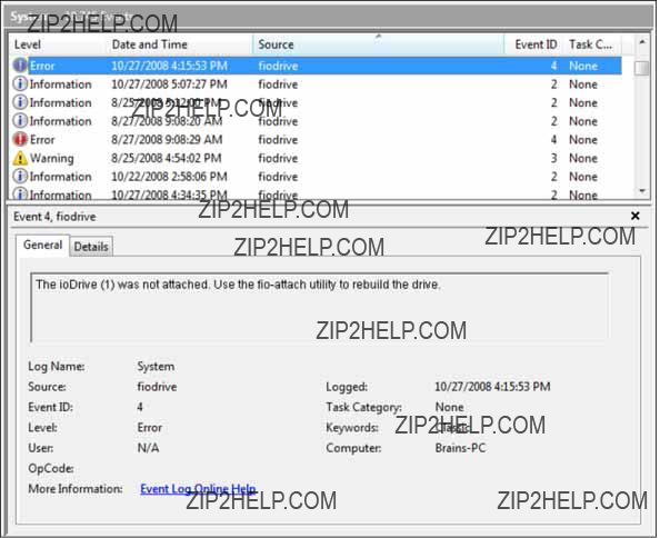
Suggested Solution:
This error may appear if the system shut down abruptly or hung. You can use either the
Message:
Warning: The ioDrive(x) was not attached because
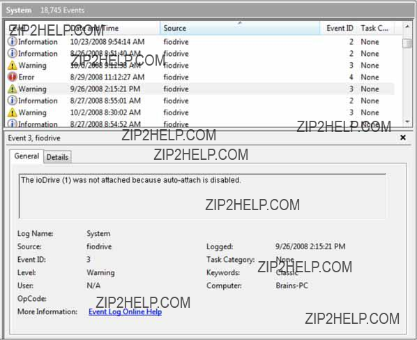
Suggested Solution:
The ioDrive must attach to the Windows operating system to be available to users and applications. (This attach normally occurs at boot time.) As part of this attach process, the ioDrive driver checks to see if there is an AutoAttach parameter in the Windows registry. If you create this Registry parameter to disable
To attach an unattached ioDrive:
1.Run ioManager.
2.Select your unattached ioDrive from the Device Tree.
3.Click the Operations tab.
4.Click Attach.
5.Confirm the Attach operation.
Your ioDrive now attaches to the Windows operating system.
To
3.4 Manual Installation Procedures
The Windows Setup program should install your needed driver and software. However, if the driver does not install, you can perform a manual install (or upgrade) using the steps below for either Windows XP Pro/Server 2003 or Windows Vista/Server 2008.
3.4.1 Manual Install on Windows XP Pro or Windows Server 2003
Windows Driver Wizard will automatically detect the new ioDrive and start to locate its driver after you restart the system. To complete the install:
1. Windows will ask you to locate the software driver.
2.If you have not done so, download and run the ioDrive Windows Setup program from http://www.dolphinics.com/support.
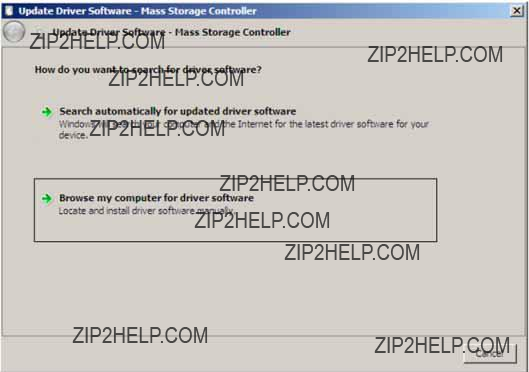
3.Return to the Update Driver dialog.
4.Click Browse my computer for driver software. The Setup program will ask you for a path to search.

5.Click Browse next to the path field. Windows will display a file dialog.
6.Select the folder with the ioDrive driver (the default is Program Files\Fusion- io\driver).
7.Click OK.
Windows will find the correct driver and install the device software. When the driver install completes, Windows will display this message:
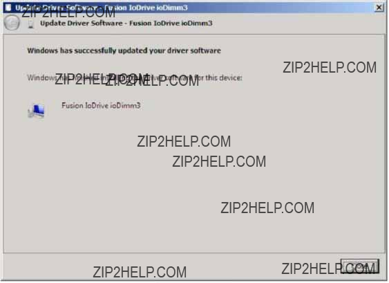
Proceed to the appropriate Windows section in this guide to perform an outdated firmware check.
3.4.2 Manual Install on Windows Vista or Windows Server 2008
The Windows Driver Wizard will automatically detect the new ioDrive and start to locate its driver after you restart the system. To complete the install:
1. Windows will ask you to locate the software driver.

2.Click Browse my computer for driver software. The Setup program will ask you for a path to search.

3.Click Browse next to the path field. Windows will display a file dialog.
4.Select the folder with the ioDrive driver (the default is Program Files\Fusion- io\driver).
5.Click OK.
6.Click Next.
Windows will find the correct driver and install the device software.
When the driver install completes, Windows will display this message:
Proceed to the appropriate section for your Windows version to perform the outdated firmware check.
3.5 Command Line Utilities Reference
The Windows Setup package installs various utilities into the Program Files\Fusion- io\utils folder. These provide a number of useful ways to access, test, and manipulate the ioDrive via the command line (Command Prompt). They include:
Utility
Purpose
Makes an ioDrive available to Windows Removes an ioDrive from Windows access
Used to perform a
Updates the ioDrive???s firmware
Note: Each utility has
Description
Attaches the ioDrive and makes it available to Windows. You can then partition, format, or set up the ioDrive as part of a RAID array using the Windows Disk Management utility. This command displays a progress bar and percentage as it completes the attach process.
Note: In most cases, the ioDrive driver automatically attaches the device at boot time. You only need to run
Syntax
where
Option
Description
Detaches the ioDrive and removes the corresponding ???fctx??? ioDrive block device from the OS. The
Caution: Before using this utility, ensure that the device you want to detach is not currently mounted and in use.
Syntax
where
Options
Description
Performs a
Note: The ioDrive ships
Caution: Use this utility with care, as it deletes all user information on the ioDrive.
Syntax
where
Options
Description
Provides detailed information about the specified or all installed ioDrive(s). The fio- status command requires that the Windows driver be loaded. If it finds no device, it displays an index number instead.
Syntax
where /dev/fctx refers to the name of this device and the x is its PCIe bus number. If you don???t specify a name,
Options
???
???
???
???
???
???
???
???
???
???
???
???
???
???
Serial number Part number
Manufacturer's name Manufacturing date
Firmware version at manufacturing time Size of the device, out of total capacity NAND manufacturer
NAND cell type (SLC, MLC, or unknown)
Size of the device in blocks Size of a block in pages
Size of a page in bytes (including ECC overhead)
Number of pads, planes and banks
Size of an
FPGA ID
???
???
???
???
???
???
???
???
???
???
???
???
???
???
Hardware UID Bus ID Vendor ID
Subsystem vendor and device IDs Device ID
PCI slot number
Internal temperature (avg. and max., since driver load) in degrees Centigrade
Ambient temperature, in degrees Centi- grade
Internal voltage: avg. and max.
Auxiliary voltage: avg. and max.
Health status: Healthy, Marginal, or Degraded, based on the percentage of good erase blocks on the device
Percentage of good data Percentage of good blocks Percentage of good metadata
Sample Output
The
Found 2 ioDrives in this system.
The
Found 2 ioDrives in this system.
fct0 Attached
ioDimm3 SN:0719 PN:001195011, Mfr:000 Date:20080709 Firmware v11791
92 GBytes, 8192 blocks, 256 pages, 47264 bytes/page (25 pads, 1 plane, 4
banks)
Nand: Samsung (ec) SLC
Error correction: 11 bits per 240 bytes, retire above 4 bits FPGA ID:000 UID:0000000002cf01326845000048f00c00
PCI: 02:00.0, Slot Number:2 Vendor ID: 1aed Device ID: 1003
Ambient temperature: 40 degC
Internal temperature: avg 44.3 degC, max 50.7 degC
Media status: healthy. 99.78% blocks good. data:99.77% good, md:100%
fct12 Not attached
ioDimm3 SN:0299 PN:001160002, Mfr:AEMS Date:20080724 Firmware v11791
154 GBytes, 8192 blocks, 256 pages, 78848 bytes/page (20 pads, 1 plane, 4
banks)
Nand: Samsung (ec) SLC
Error correction: 11 bits per 240 bytes, retire above 4 bits FPGA
Internal temperature: avg 37.9 degC, max 42.8 degC
Media status: healthy. 99.87% blocks good. data:99.82% good, md:100%
Description
Updates the ioDrive???s firmware. This utility scans the PCIe bus for all attached ioDrives and updates up to 256 total devices. Each ioDrive displays a progress bar and percentage as the update completes. To update one or more specific devices, use the
Caution: The default action (without using the
Syntax
where <iodrive_version> is the path and firmware archive file.
Options
Force Upgrade (Also used to perform a rollback to an earlier firmware version.)
List firmware available in the archive.
Pretend: Show what updates would be done (the firmware is not modified). This option requires the
Caution: Use the
Note: All three external LED indicators will light during the update process.
3.6 Enabling SNMP
The ioDrive also supports monitoring using SNMP or Windows Management Instrumentation (WMI). The Windows Setup package places the ioDrive SNMP extension agent DLL and MIB into Program
To install and enable the extension agent:
1.Copy
2.Open Regedit and create the following registry key:
3.In Regedit, locate the following registry key:
HKEY_LOCAL_MACHINE\SYSTEM\CurrentControlSet\Ser- vices\SNMP\Parameters\ExtensionAgents
4.Modify this key to include a String Value. Number it next in the list of agents.
5.Modify this value with the following:
6.Save and exit Regedit.
7.Stop and restart the Windows SNMP service.
You can now monitor your ioDrive using SNMP. By default, the ioDrive agent uses the cpqIODrv.mib in the Program
3.6.1 Windows Management Instrumentation (WMI)
WMI is the Microsoft implementation of the Common Information Model (CIM) and
1.Click on Start/Control Panel.
2.Click on Add/Remove Programs (Programs and Features in Vista/Server 2008).
3.Click on the Add/Remove Windows Components button.
4.Select Management & Monitoring Tools.
5.Click on the Details button.
6.Check the box labeled WMI Windows Installer Provider.
7.Click OK.
8.Click Next.
Follow the
3.6.1.1 Install WMITools
Next, install the WMITools package:
1.Enter ???WMITools??? in the Downloads search box at the top of the page at www.microsoft.com/downloads.
2.Download the package to a convenient folder.
3.Click on the package to launch the setup process.
4.Follow the onscreen instructions to complete the install.
3.6.1.2Convert the MIB File
You must now create and register the WMI .MOF version of the SNMP MIB file.
1.Download a copy of the
2.Open a Command Prompt and navigate to this directory.
3.To create the MOF version of the MIB file, type in the command:
C:\WINDOWS\system32\wbem\snmp\smi2smir /g
4. To register this MOF file with WMI, type in the command:
C:\WINDOWS\system32\wbem\mofcomp cpqIODrv.mof
Your management system is now ready for active monitoring.