Sensotronic Brake Control
(SBC)
R230 and W211: Starting MY2003
1
327 HO 09 SBC (WJB)
Sensotronic Brake Control
(SBC)
R230 and W211: Starting MY2003
1
327 HO 09 SBC (WJB)
Objectives
At the end of this presentation, you should be able to:
1.Explain the function of and purpose for SBC
2.Describe the customer interface with SBC
3.List the hydraulic and electronic components used for SBC
4.Describe how the ???normal??? feel of the brake pedal is maintained
5.Explain emergency operation of the SBC braking system
6.Describe ???temperature compensation???
7.Explain ???Deactivation??? and describe when it is necessary to do it
8.???Activate??? the SBC system
9.Locate tools and the proper procedure for bleeding brakes
These technical training materials are current as of the date noted on the materials, and may be revised or updated without notice. Always check for revised or updated information.
To help avoid personal injury to you or others, and to avoid damage to the vehicle on which you are working, you must always ref er to the latest Mercedes
Illustrations and descriptions in this training reference are based on preliminary information and may not correspond to the final US version vehicles. Refer to the official introduction manual and WIS
Reproduction by any means or by any information storage and retrieval system or translation in whole or part is not permitted without written authorization from Mercedes
Contents
3
SBC Incorporates these Functions:
ABS (Anti lock Brakes 1984)
+ASR (Automatic Slip Regulation 1991)
+ETS (Electronic Traction System 1995)
+ESP (Electronic Stability Program 1996)
+BAS (Brake Assist System 1998)
4
Advantages of SBC
???Improves metering of required brake pressure
???each wheel can be precisely controlled
???Improved BAS function
???monitors release of accelerator pedal and application of brake
???maximum pressure available immediately
???
???when the BAS function is anticipated, slight pressure is applied
5
Advantages of SBC
???Electronic Brake Proportioning: EBP
???allows brake proportioning front to back and side to side
???No pedal vibration during ABS operation
???eliminates ???distraction??? to the driver during critical moments
???indicator light in instrument cluster signals traction loss
???Improved driving dynamics: ABS, ASR, and ESP
???faster response to brake request inputs
6

Advantages of SBC
???Pressure reduction at standstill
???reduces stress on components
???Dry braking function
???wiper input via CAN
???~every 7 to 14 minutes
???brake actuation changes time interval
7
Driving with SBC -
SBC is functional as soon as it is ???wakened??? by:
???opening a door (via CAN)
???operating the central locking system (via CAN)
???depressing the brake pedal
???turning key to position 1
???operating parking brake

Driving with SBC ???
When SBC performs a PDC after a
 Warning! Pressure is applied to brake calipers (~60 bar)
???reservoir pressure (if low, it will be corrected by running the high pressure charge pump in the hydraulic unit)
???pressure sensors
???control valves
???leak tests
???operational checks
Note:
Driving with SBC ??? Delayed Off Function
Time that SBC remains operational after use:
???with vehicle stationary and was locked = 20 seconds
???with vehicle stationary and ignition in ???0???,
brake pedal not operated = 2 minutes
??? with vehicle stationary, ignition in ???0???,
brake pedal operated in delayed off phase and released again = 4 minutes
10
Warning Display
Complete ESP control module failure -
Instrument cluster will scroll through failure displays
11
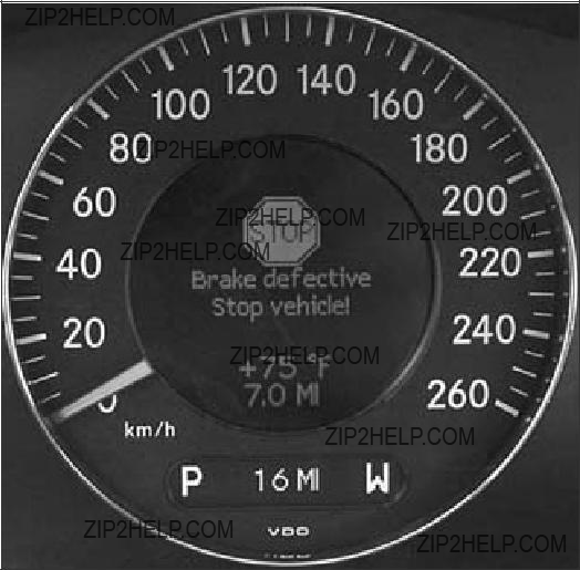
Warning Display
SBC control module failure

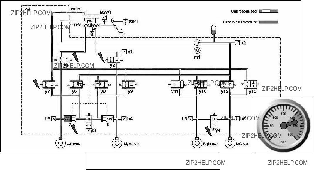
SBC Components
???Brake Operating Unit (BOU)
???Wheel speed sensors
???Traction System Hydraulic Unit (A7/3)
13
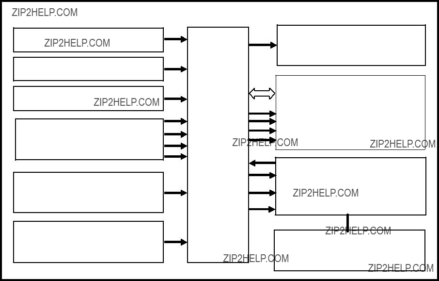
W211 System Overview
14

R230 System Overview
15

X11/4 Diagnosis Connection
16

Brake Operating Unit - (BOU)
17

Brake Operating Unit
The Brake Operating Unit (BOU) consists of the following:
???Brake fluid reservoir (Do not overfill!)
 ??? SBC pedal value sensor
 ??? Tandem master cylinder
 ??? Brake pressure simulator
(Note: no vacuum booster)
18

Master Cylinder
??? Fluid level sensor
 ??? Fluid return line
 ??? Do not overfill
 ??? Hydraulic lines to SBC
 ??? Supply hose to SBC
19

Fluid Reservoir Cover
??? Ultraviolet protection (211 only)
20
Pedal Value Sensor - (B37/1)
??? Contains two hall effect sensors
??? Converts pedal travel value to an electrical signal
??? Provides input to SBC control module A7/3
21

BOU Tandem Master Cylinder
Fluid reservoir
Fill valves
Primary piston
Floating piston
22


Normal Braking - Increased Pressure
??? Increasing pedal travel causes the larger spring to compress, providing harder pedal feel
24

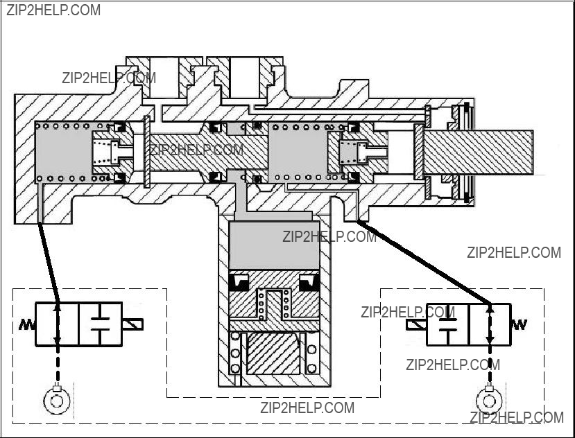

Traction System Hydraulic Unit (A7/3)
Consists of:
 ??? SBC control module (A7/3n1)
??? High pressure charge pump (A7/3m1)
 ??? Pressure reservoir
27

Traction System Hydraulic Unit
A7/3
28
Legend
29

Emergency Operation Circuit
??? Pressure applied directly to front calipers
??? y1 and y2 not energized
??? b1, b3, and b4 pressure sensors may provide information to SBC control module
??? Media separator/Dividing piston 7 and 8 isolate emergency circuit from normal circuit
30
Brake Pressure Supply
???pressure reservoir charged to 160 bar
???the high pressure charge pump runs as needed
???pressure blocked by y6, y8,
GF
Three Pressure Stages
Same pressure stages as used with ABS functions:
???Pressure apply
???Pressure hold
???Pressure release
32

Pressure Apply - Rear Wheels
???Brake pedal depressed
???B37/1 and b1 report brake application to control module
???y1 and y2 energized
???y10 and y12 intake control valves energized
???Pressure at each rear wheel monitored by b5 and b6
???Balance valve y4 not energized
Brake pedal pressure
Reservoir pressure
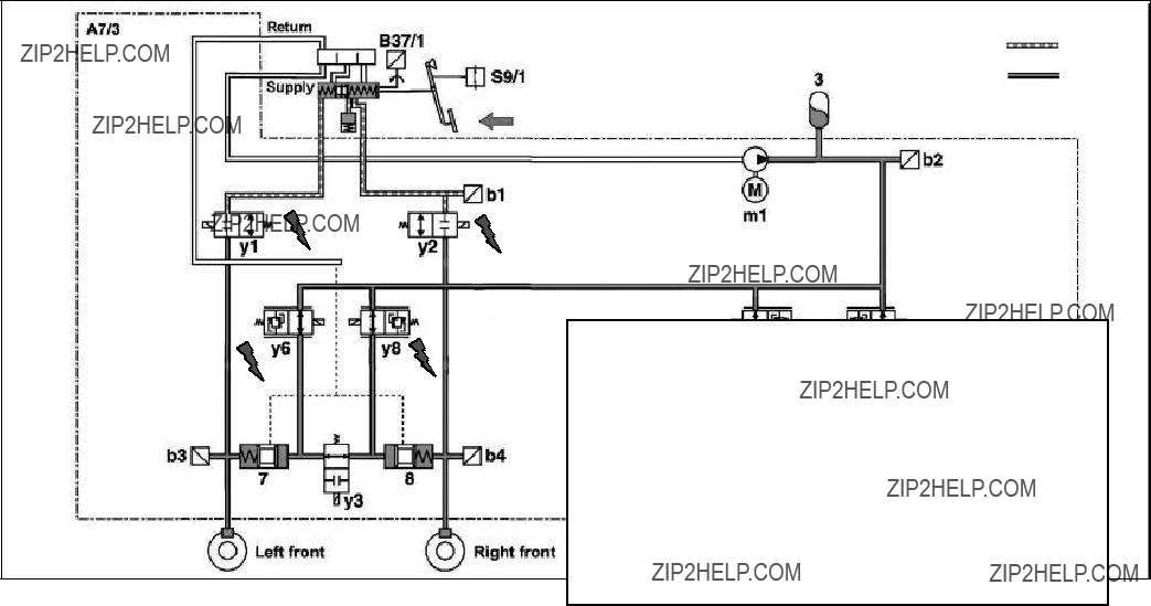
Pressure Apply - Front Wheels
Brake pedal pressure
Reservoir pressure
???y6 and y8 energized
???pressure applied to left and right dividing pistons 7 and 8
???7 and 8 apply pressure to caliper
???pressure at each wheel monitored by b3 and b4
???Balance valve y3 not energized
34

Pressure Apply - All Wheels

Pressure Hold - All Wheels
??? y6, y8, y10, y12
36

Pressure Reduction - All Wheels
??? y7, y9, y11, y13
37

Temperature Compensation
During continuous brake use the fluid in the calipers expand, this:
???creates high pressure
???prevents valves 7 & 8 from moving
To reduce this pressure, y1 and y2 are pulsed
38

Deactivation
SBC must be deactivated with SDS before any work is performed on the system. This will prevent the
Deactivating the system will:
??? empty the pressure reservoir
(a lower pressure with no volume may be retained)
??? prevent the charge pump from operating
???Note: the warning buzzer is deactivated when accessing SBC with the SDS.
39
Deactivation
SBC must be deactivated PRIOR to:
???working on the hydraulic system
???removing or installing brake pads
???replacing rotors
???replacing the pressure reservoir
???replacing the BOU
???replacing the SBC hydraulic unit (A7/3)
40
Deactivation
Charge pump disabled and accumulator fluid returned to the reservoir!
41
Pressure at A7/3b2
System Activation
Activation must be performed anytime the system has been deactivated, BEFORE the engine is started!
Failure to activate will prevent proper operation and create fault codes!
Activating SBC with SDS will:
???charge the accumulator
???perform a Predrive Check
???move the pads towards the rotors with ~60 bar pressure
???erase the fault memory
(Note: may have to activate several times to position the brake pads)
42

System Activation
43
Activation - Left Front

Activation - Right Front

Activation - Right Rear

Activation - Left Rear

Activation - Recharge
48
Bleeding the Brake System
Proper system bleeding is critical!
Follow directions in SDS
???Bleeding must be performed using the SDS
???Pressure at bleeder valves will exceed 100 bar (Hold the bleeder hose securely)
???Bleeding may require ~1.5 hours
???Bleeding may use ~ 1.5 liters of brake fluid
49

Equipment Required
???Pressure bleeder
???Adapters
???Fluid receptacle
???SDS - follow instructions carefully
211 589 01 91 00
CAUTION:
Extremely high pressure at bleeder!
Bleeding the Brake System
Connect equipment and follow steps in SDS
51
Acronym List
(Used in This Handout.)

Appendix
53